THE GAP ANTENNA Segment 1 The GAP Challenger


- Slides: 7
THE GAP ANTENNA Segment 1 The GAP Challenger DX-8 Vertical Antenna What is it? Why is it so special? What does it look like? What can it do?
THE GAP CHALLENGER DX-8 ANTENNA What is it? � The Challenger antenna is the first production multiband antenna utilizing “GAP technology” first arriving on the Ham scene in 1988. � Competitively priced at about $425 � Thousands of Challengers are now in use throughout the world. From the jungle of New Guinea to the bitter cold of Finland, Challenger DX-8, with its elevated feed, links its user to the rest of the world. � Reviewed by many. Why is it so special? � The antenna is not a traditional ¼ wave vertical; it is a vertical dipole, which gives it several advantages over a standard ¼ wave vertical. Chiefly the reduced number of radials. It is one of only a few manufactured ‘vertical’ antennas that will cover 8 bands - more than any other multi-band vertical.
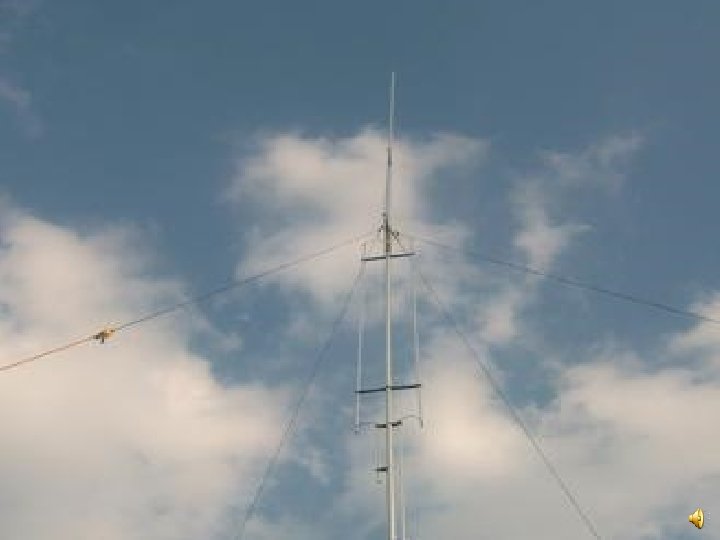
THE GAP CHALLENGER DX-8 ANTENNA What does it look like? � Standing proudly three inches off the ground or mounted on a structure or supporting pole, the Challenger DX-8 is 31 ½ feet of radiating aluminum tubing. What can it do? � According to the manufacturer, “Challenger is…capable of operating on eight separate bands from 3. 5 MHz to 144 MHz. Its operating bands are 80 m, 40 m, 20 m, 15 m, 12 m, 10 m, 6 m, and 2 m. Over 130 KHz of bandwidth is provided on 80 m. On 2 m, the Challenger is a great base station antenna. ” Most reviews, however, favor operations on 80 m, 40 m, and 20 m, with most disagreeable results for the other frequencies.
THE GAP CHALLENGER DX-8 ANTENNA How Does it Work? A review by Peter Hart (G 3 SJX), in the December 1991 issue of Radio Communication, explains the basic Gap antenna concept. � The tubing is split about halfway up a 31 -foot aluminum tube pole by a non-conducting section; in essence, it is two, stacked � The outer conductor (braid) of the specially-made coax is connected to the top of sections. the lower section, where the inner conductor passes through a series stub � � � attached to the bottom of the upper section. The feeder and the stub are formed from a single length of 1/4 inch diameter thick-braided coax with the braiding suitably cut at the gap feed point. The stub is electrically ¼ wavelength long at 3. 5 MHz and is terminated at the top end with a capacitor, that is capable of resonating at a variety of frequencies. The stub is contained within the upper section by stuffing the coax inside the tubing.
THE GAP CHALLENGER DX-8 ANTENNA How Does it Work? The other notable feature of the antenna is that there are tuning rods protruding both upward and downward from the gap. � On the low frequency bands, these tuning rods act as capacity loading. � On the higher frequency bands, the length of the tuning rods becomes significant in terms of wavelength and these must be considered as transmission lines. � The lower two tuning rods each comprises transmission lines with higher impedance sections connecting to lower impedance sections. The result is three shunt stubs across the gap, which gives a multiresonance and matches the antenna across different bands. � However, the situation is probably more complex than this, and the tuning rods almost certainly radiate more so on the higher bands, particularly where they are at resonant length.
THE GAP CHALLENGER DX-8 ANTENNA What’s next? Assembly of the DX-8