The First Law of Thermodynamics Cyclic Processes Meeting


")


 (Heat Transfer)")

")


 a 1")


 1000 K 100 KJ W 300 K Ciclo de Carnot W=?")
")
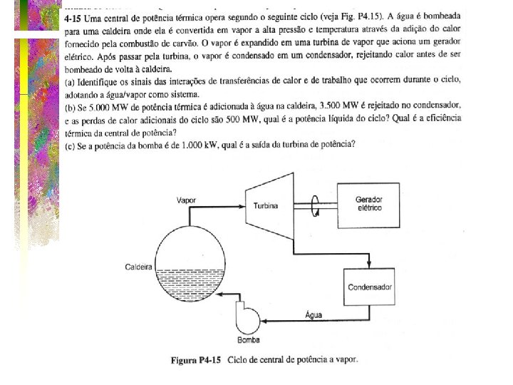
 WT>0 Turbina Qh>0 Caldeira (5000) Condensador Qc<0 (3500) Bomba Wb<0 Qmeio<0")
 T 550ºC P 1>P 2 30ºC s")
 Qh=+180 k. W 1 Compressor Aquecedor 1000ºC 2 Turbina W<0 W>0")

- Slides: 85
The First Law of Thermodynamics & Cyclic Processes Meeting 7 Section 4 -1
Thermodynamic Cycle • Is a series of processes which form a closed path. • The initial and the final states are coincident.
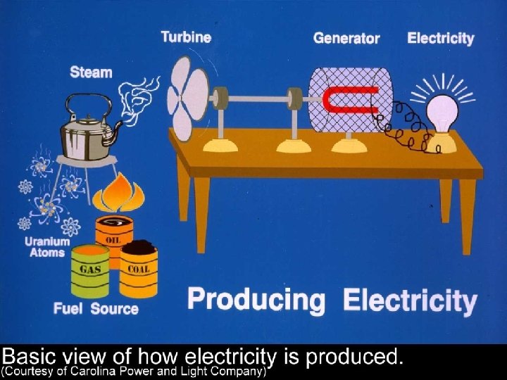
For What Thermodynamics Cycles Are For? • Thermal engines work in a cyclic process. • A Thermal engines draws heat from a hot source and rejects heat to a cold source producing work
Heat Engine Power Cycles Hot body or source Qin System, or heat engine Qout Cold body or sink Wcycle
Heat Engine Efficiency Hot body or source QH System, or heat engine QL Cold body or sink Wcycle
Qout Wcycle System Qin Cold body or sink HEAT PUMP Hot body or source REFRIGERATOR Refrigerators and heat pumps
Energy analysis of cycles 4 3 1 2 For the cycle, E 1 = 0, or
For cycles, we can write: Qcycle = Wcycle Qcycle and Wcycle represent net amounts which can also be represented as:
TEAMPLAY • A closed system undergoes a cycle consisting of two processes. During the first process, 40 Btu of heat is transferred to the system while the system does 60 Btu of work. During the second process, 45 Btu of work is done on the system. (a) Determine the heat transfer during the second process. (b) Calculate the net work and net heat transfer of the cycle.
TEAMPLAY Win = 45 Btu 2 B Qin=40 Btu 1 A Wout=60 Btu
Carnot Cycle • The Carnot cycle is a reversible cycle that is composed of four internally reversible processes. – Two isothermal processes – Two adiabatic processes
Carnot cycle for a gas The area represents the net work TL
P-v Diagram of the Reversed Carnot Cycle • TL
The Carnot cycle for a gas might occur as visualized below. TL TH TH TL QL TL
Execution of the Carnot Cycle in a Closed System • (Fig. 5 -43)
• This is a Carnot cycle involving two phases -- it is still two adiabatic processes and two isothermal processes. TL • It is always reversible -- a Carnot cycle is reversible by definition. TL TL
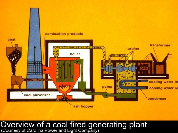
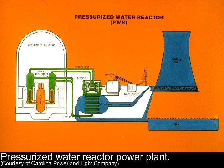
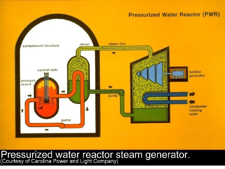
Vapor Power Cycles • We’ll look specifically at the Rankine cycle, which is a vapor power cycle. • It is the primary electrical producing cycle in the world. • The cycle can use a variety of fuels.
Question …. . How much does it cost to operate a gas fired 1000 MW(output) power plant with a 35% efficiency for 24 hours/day for a full year if fuel cost are $2. 00 per 106 Btu? $467, 952. 27/day $170, 801, 979/year
Question …. If you could improve the efficiency of a 1000 MW power plant from 35% to 36%, what would be a reasonable charge for your services? Let’s assume $2. 00 per million BTUs fuel charge and 24 hr/day operation. $12, 998. 67/day $4, 744, 499/year
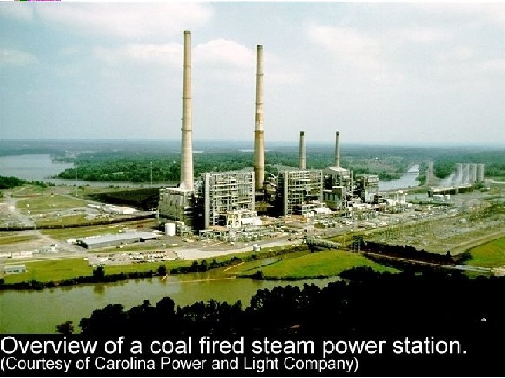
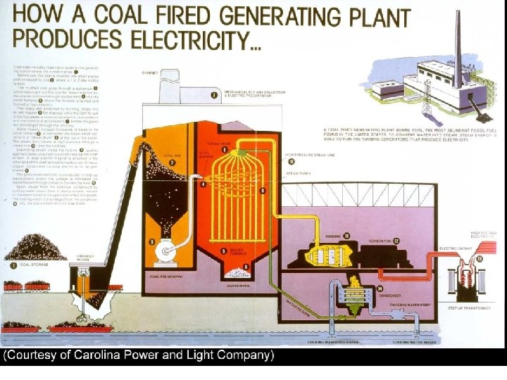
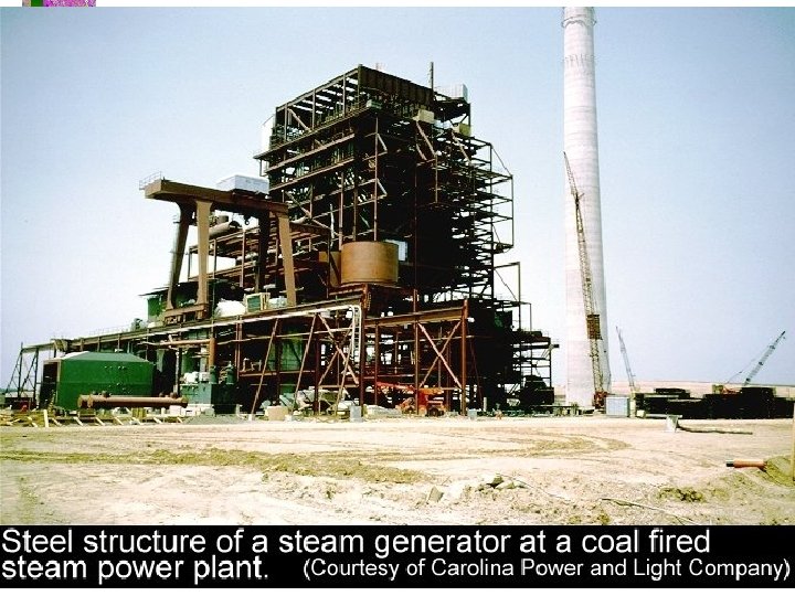
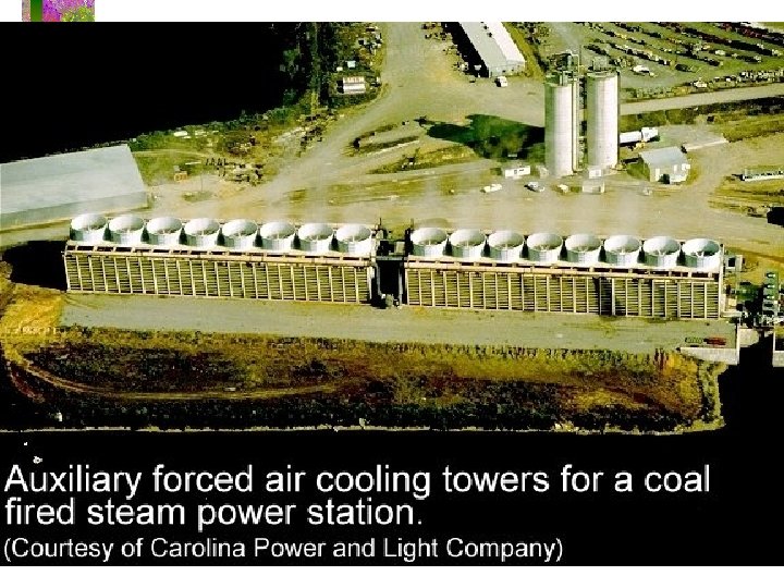
Vapor-cycle Power Plants
We’ll simplify the power plant
Carnot Vapor Cycle Low thermal efficiency compressor and turbine must handle two phase flows
Carnot Vapor Cycle • The Carnot cycle is not a suitable model for vapor power cycles because it cannot be approximated in practice.
Rankine Cycle • The model cycle for vapor power cycles is the Rankine cycle which is composed of four internally reversible processes: constantpressure heat addition in a boiler, isentropic expansion in a turbine, constant-pressure heat rejection in a condenser, and isentropic compression in a pump. Steam leaves the condenser as a saturated liquid at the condenser pressure.
Refrigerator and Heat Pump Objectives The objective of a refrigerator is to remove heat (QL) from the cold medium; the objective of a heat pump is to supply heat (QH) to a warm medium •
Inside The Household Refrigerator
Ordinary Household Refrigerator
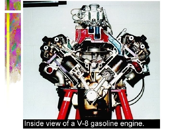
Gas Power Cycle • A cycle during which a net amount of work is produced is called a power cycle, and a power cycle during which the working fluid remains a gas throughout is called a gas power cycle.
Actual and Ideal Cycles in Spark-Ignition Engines v v
Otto Cycle qin qout P-V diagram T-S diagram (Work) (Heat Transfer)
Performance of cycle Thermal Efficiency: Need to know QH and QL
Otto Cycle • Heat addition 2 -3 QH = m. CV(T 3 -T 2) • Heat rejection 4 -1 QL = m. CV(T 4 -T 1) • or in terms of the temperature ratios qin qout
Otto Cycle • 1 -2 and 3 -4 are adiabatic process, using the adiabatic relations between T and V qin qout
Cycle performance with cold air cycle assumptions This looks like the Carnot efficiency, but it is not! T 1 and T 2 are not constant. What are the limitations for this expression?
Thermal Efficiency of Ideal Otto Cycle • Under cold-air-standard assumptions, thermal efficiency of the ideal Otto cycle is where r is the compression ratio and k is the specific heat ratio Cp /Cv.
Effect of compression ratio on Otto cycle efficiency k = 1. 4
Otto Cycle The thermal efficiency of the Otto Cycle increases with the specific heat ratio k of the working fluid
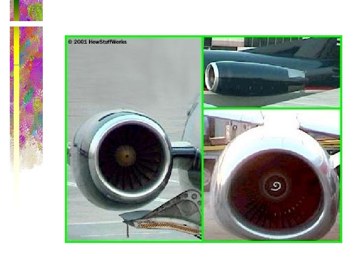
Brayton Cycle • This is another air standard cycle and it models modern turbojet engines.
Brayton Cycle Proposed by George Brayton in 1870! http: //www. pwc. ca/en_markets/demonstration. html
jet engine with afterburner for military applications.
Schematic of A Turbofan Engine
Illustration of A Turbofan Engine
Turboprop burner compressor turbine
Schematic of a Turboprop Engine
Other applications of Brayton cycle • Power generation - use gas turbines to generate electricity…very efficient • Marine applications in large ships • Automobile racing - late 1960 s Indy 500 STP sponsored cars
An Open-Cycle Gas-Turbine Engine
A Closed-Cycle Gas-Turbine Engine
Brayton Cycle • The ideal cycle for modern gasturbine engines is the Brayton cycle, which is made up of four internally reversible processes: isentropic compression, constant pressure heat addition, isentropic expansion, and constant pressure heat rejection.
Turbojet Engine Basic Components and T-s Diagram for Ideal Turbojet Cycle
P-v and T-s Diagrams for the Ideal Brayton Cycle
Brayton Cycle • 1 to 2 --isentropic compression in the compressor • 2 to 3 --constant pressure heat addition (replaces combustion process) • 3 to 4 --isentropic expansion in the turbine • 4 to 1 --constant pressure heat rejection to return air to original state
Brayton Cycle • Because the Brayton cycle operates between two constant pressure lines, or isobars, the pressure ratio is important. • The pressure ratio is not a compression ratio.
Brayton cycle analysis Let’s assume cold air conditions and manipulate the efficiency expression:
Brayton cycle analysis Using the isentropic relationships, Let’s define:
Brayton Cycle • Because the Brayton cycle operates between two constant pressure lines, or isobars, the pressure ratio is important. • The pressure ratio is just that--a pressure ratio. • A compression ratio is a volume ratio (refer to the Otto Cycle).
Brayton Cycle • The pressure ratio is • Also
Brayton cycle analysis Then we can relate the temperature ratios to the pressure ratio: Plug back into the efficiency expression and simplify:
Ideal Brayton Cycle What does this expression assume?
Thermal Efficiency of Brayton Cycle • Under cold-air-standard assumptions, the Brayton cycle thermal efficiency is where rp = Pmax/Pmin is the pressure ratio and k is the specific heat ratio. The thermal efficiency of the simple Brayton cycle increases with the pressure ratio.
Brayton Cycle k = 1. 4
Thermal Efficiency of the Ideal Brayton Cycle
Evaporação a pressão constante Um sistema pistão cilindro contêm, inicialmente, três kg de H 2 O no estado de líquido saturado com 0. 6 MPa. Calor é adicionado, vagarosamente, a água fazendo com que o pistão se movimente de tal maneira que a pressão seja constante. Quanto de trabalho é realizado pela água? Quanta energia deve ser transferida para a água de tal maneira que ao final do processo ela esteja no estado de vapor saturado? Fronteira do Sistema Representação do processo
processo a pressão const. Primeira Lei: 1 Q 2 – 1 W 2 = U 2 – U 1 mas o trabalho 1 W 2 = Patm*(V 2 -V 1), Logo 1 Q 2 = (P 2 V 2+U 2)-(P 1 V 1+U 1) = H 2 -H 1 Onde h 2 é a entalpia do vapor saturado e h 1 é a entalpia do líquido. Na tabela 1 -2 termodinâmico para 0. 6 MPa, tem-se que h 2 = 2756, 8 KJ/kg e h 1 = 670, 56 KJ/kg. Considerando 3 kg de H 2 O, então o calor transferido será de 3*(2756 -670) = 6259 KJ.
Resfriamento com Gelo Seco 0. 5 kg de gelo seco (CO 2) a 1 atm é colocado em cima de uma fatia de picanha. O gelo seco sublima a pressão constante devido ao fluxo de calor transferido pela picanha. Ao final do processo todo CO 2 está no estado de vapor (foi completamente sublimado). Determine a temperatura do CO 2 e quanto de calor ele recebeu da picanha. Fronteira do Sistema Representação do processo
Resfriamento com Gelo Seco – processo a pressão const. Primeira Lei: 1 Q 2 – 1 W 2 = U 2 – U 1 mas o trabalho 1 W 2 = Patm*(V 2 -V 1), Logo 1 Q 2 = (P 2 V 2+U 2)-(P 1 V 1+U 1) = H 2 -H 1 Onde h 2 é a entalpia do vapor saturado e h 1 é a entalpia do sólido. No diagrama termodinâmico para Patm, tem-se que h 2 = 340 KJ/kg e h 1 = -220 KJ/kg. Considerando 0. 5 kg de CO 2, então o calor transferido será de 280 KJ. A temperatura de saturação do CO 2 será de 175 K (-98 o. C)
LIQUID SO LI D VAPOR
Solução de Exercícios Cap 4
Ex 4. 13) 1000 K 100 KJ W 300 K Ciclo de Carnot W=? Qc=?
Ex 4. 14)
Ex 4. 15) WT>0 Turbina Qh>0 Caldeira (5000) Condensador Qc<0 (3500) Bomba Wb<0 Qmeio<0 (500)
Ex 4. 16) T 550ºC P 1>P 2 30ºC s
Ex 4. 17) Qh=+180 k. W 1 Compressor Aquecedor 1000ºC 2 Turbina W<0 W>0 4 100ºC Condensador QL=-110 k. W 3
Rendimento Máximo -> Rendimento de Carnot Ciclo Brayton Conhecer Pressões