
THE ETHERNET ROADMAP PANEL Scott Kipp March 15

- Slides: 39
THE ETHERNET ROADMAP PANEL Scott Kipp March 15, 2015 www. ethernetalliance. org
Agenda • 11: 30‐ 11: 40 – The 2015 Ethernet Roadmap – Scott Kipp, Brocade • 11: 40‐ 11: 50 – Ethernet Technology Drivers ‐ Mark Gustlin, Xilinx • 11: 50‐ 12: 00 – Copper Connectivity in the 2015 Ethernet Roadmap ‐ David Chalupsky, Intel • 12: 00‐ 12: 10 – Implications of 50 G SERDES Speeds on Ethernet speeds ‐ Kapil Shrikhandre, Dell • 12: 10‐ 12: 30 – Q&A
Disclaimer • Opinions expressed during this presentation are the views of the presenters, and should not be considered the views or positions of the Ethernet Alliance.
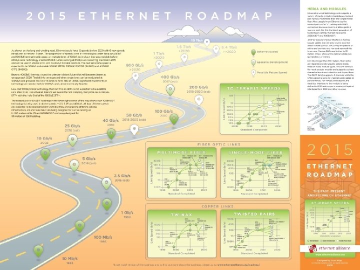
THE 2015 ETHERNET ROADMAP Scott Kipp March 15, 2015 www. ethernetalliance. org
Optical Fiber Roadmaps
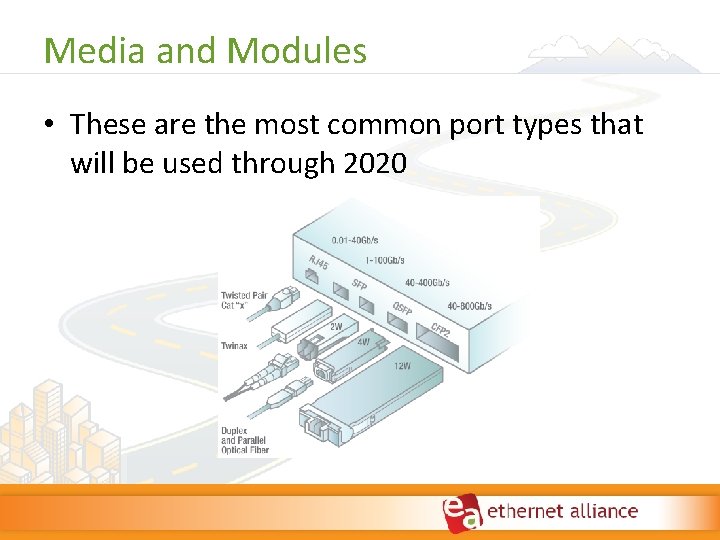
Media and Modules • These are the most common port types that will be used through 2020
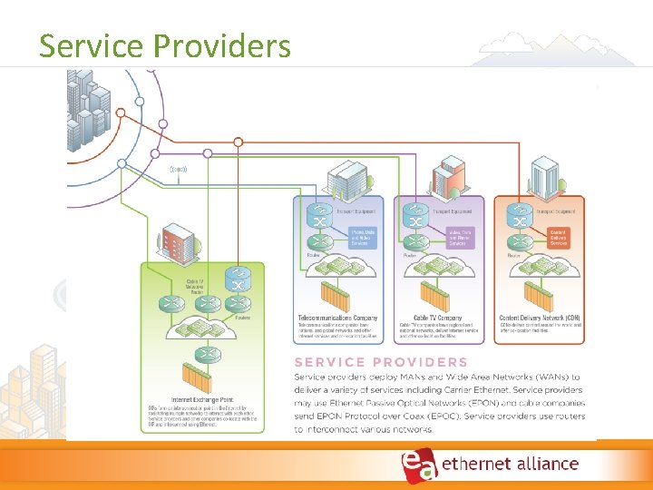
Service Providers
More Roadmap Information • Your free map is available after the panel • Free downloads at www. ethernetalliance. org/roadmap/ – Pdf of map – White paper – Presentation with graphics for your use • Free maps at Ethernet Alliance Booth #2531
ETHERNET TECHNOLOGY DRIVERS Mark Gustlin ‐ Xilinx www. ethernetalliance. org
Disclaimer • The views we are expressing in this presentation are our own personal views and should not be considered the views or positions of the Ethernet Alliance
Why So Many Speeds? • New markets demand cost optimized solutions – 2. 5/5 Gb. E are examples of an optimized data rate for Enterprise access • Newer speeds becoming more difficult to achieve – 400 Gb. E being driven by achievable technology • 25 Gb. E is an optimization around industry lane rates for Data Centers
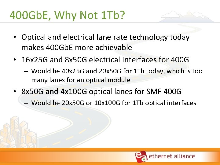
400 Gb. E, Why Not 1 Tb? • Optical and electrical lane rate technology today makes 400 Gb. E more achievable • 16 x 25 G and 8 x 50 G electrical interfaces for 400 G – Would be 40 x 25 G and 20 x 50 G for 1 Tb today, which is too many lanes for an optical module • 8 x 50 G and 4 x 100 G optical lanes for SMF 400 G – Would be 20 x 50 G or 10 x 100 G for 1 Tb optical interfaces
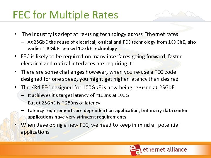
FEC for Multiple Rates • The industry is adept at re‐using technology across Ethernet rates – At 25 Gb. E the reuse of electrical, optical and FEC technology from 100 Gb. E, also earlier 100 Gb. E re‐used 10 Gb. E technology • FEC is likely to be required on many interfaces going forward, faster electrical and optical interfaces are requiring it • There are some challenges however, when you re‐use a FEC code designed for one speed, you might get higher latency than desired • The KR 4 FEC designed for 100 Gb. E is now being re‐used at 25 Gb. E – It achieves it’s target latency of ~100 ns at 100 G – But at 25 Gb. E is ~ 250 ns of latency – Latency requirements are dependent on application, but many data center applications have very stringent requirements • When developing a new FEC, we need to keep in mind all potential applications
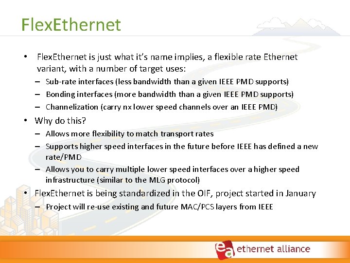
Flex. Ethernet • Flex. Ethernet is just what it’s name implies, a flexible rate Ethernet variant, with a number of target uses: – Sub‐rate interfaces (less bandwidth than a given IEEE PMD supports) – Bonding interfaces (more bandwidth than a given IEEE PMD supports) – Channelization (carry nx lower speed channels over an IEEE PMD) • Why do this? – Allows more flexibility to match transport rates – Supports higher speed interfaces in the future before IEEE has defined a new rate/PMD – Allows you to carry multiple lower speed interfaces over a higher speed infrastructure (similar to the MLG protocol) • Flex. Ethernet is being standardized in the OIF, project started in January – Project will re‐use existing and future MAC/PCS layers from IEEE
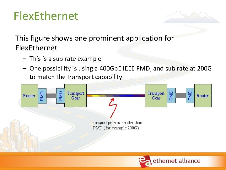
Flex. Ethernet This figure shows one prominent application for Flex. Ethernet Transport Gear Transport pipe is smaller than PMD (for example 200 G) PMD Transport Gear PMD Router PMD – This is a sub rate example – One possibility is using a 400 Gb. E IEEE PMD, and sub rate at 200 G to match the transport capability Router
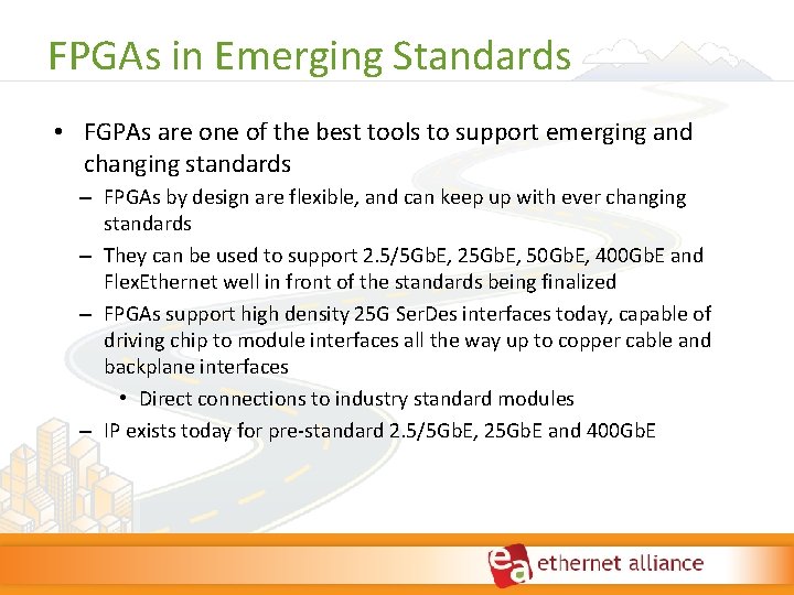
FPGAs in Emerging Standards • FGPAs are one of the best tools to support emerging and changing standards – FPGAs by design are flexible, and can keep up with ever changing standards – They can be used to support 2. 5/5 Gb. E, 25 Gb. E, 50 Gb. E, 400 Gb. E and Flex. Ethernet well in front of the standards being finalized – FPGAs support high density 25 G Ser. Des interfaces today, capable of driving chip to module interfaces all the way up to copper cable and backplane interfaces • Direct connections to industry standard modules – IP exists today for pre‐standard 2. 5/5 Gb. E, 25 Gb. E and 400 Gb. E
COPPER CONNECTIVITY IN THE 2015 ETHERNET ROADMAP AKA, WHAT’S THE COMPETITION DOING? David Chalupsky March 24, 2015 www. ethernetalliance. org
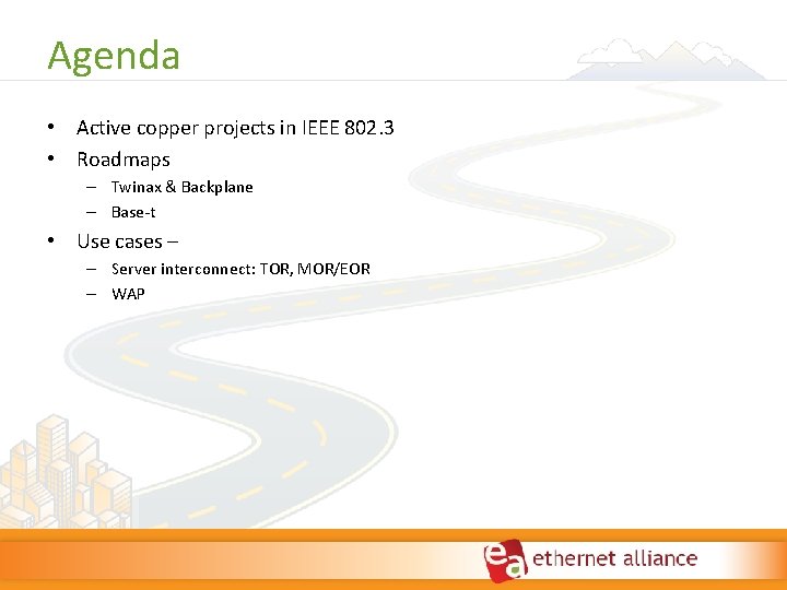
Agenda • Active copper projects in IEEE 802. 3 • Roadmaps – Twinax & Backplane – Base‐t • Use cases – – Server interconnect: TOR, MOR/EOR – WAP
Disclaimer • Opinions expressed during this presentation are the views of the presenters, and should not be considered the views or positions of the Ethernet Alliance.
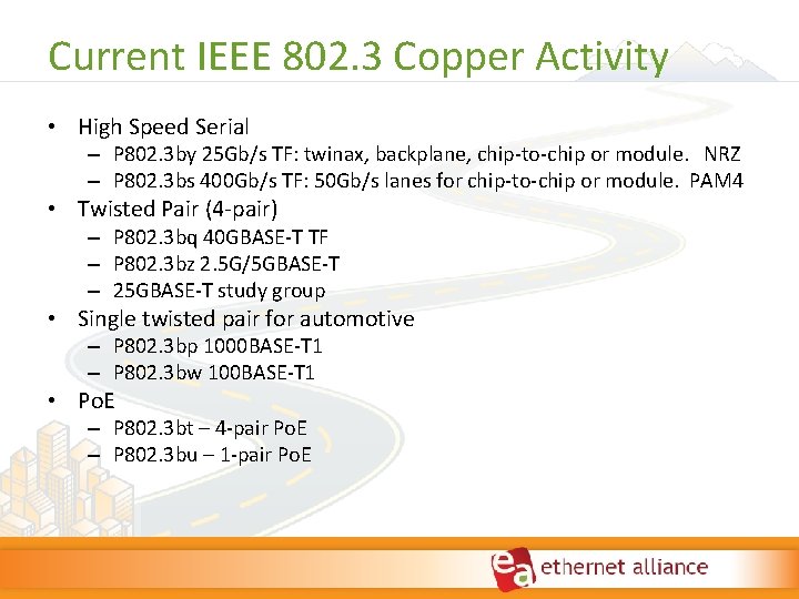
Current IEEE 802. 3 Copper Activity • High Speed Serial – P 802. 3 by 25 Gb/s TF: twinax, backplane, chip‐to‐chip or module. NRZ – P 802. 3 bs 400 Gb/s TF: 50 Gb/s lanes for chip‐to‐chip or module. PAM 4 • Twisted Pair (4‐pair) – P 802. 3 bq 40 GBASE‐T TF – P 802. 3 bz 2. 5 G/5 GBASE‐T – 25 GBASE‐T study group • Single twisted pair for automotive – P 802. 3 bp 1000 BASE‐T 1 – P 802. 3 bw 100 BASE‐T 1 • Po. E – P 802. 3 bt – 4‐pair Po. E – P 802. 3 bu – 1‐pair Po. E
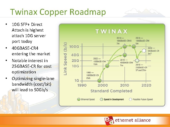
Twinax Copper Roadmap • 10 G SFP+ Direct Attach is highest attach 10 G server port today • 40 GBASE‐CR 4 entering the market • Notable interest in 25 GBASE‐CR for cost optimization • Optimizing single‐lane bandwidth (cost/bit) will lead to 50 Gb/s
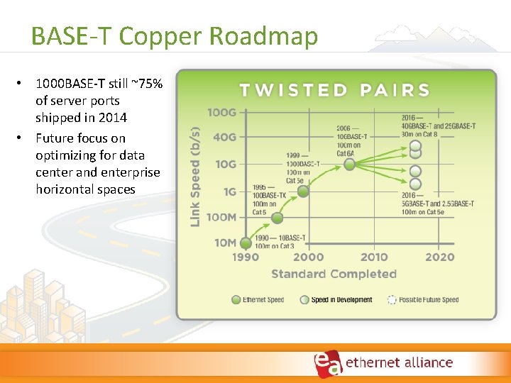
BASE‐T Copper Roadmap • 1000 BASE‐T still ~75% of server ports shipped in 2014 • Future focus on optimizing for data center and enterprise horizontal spaces
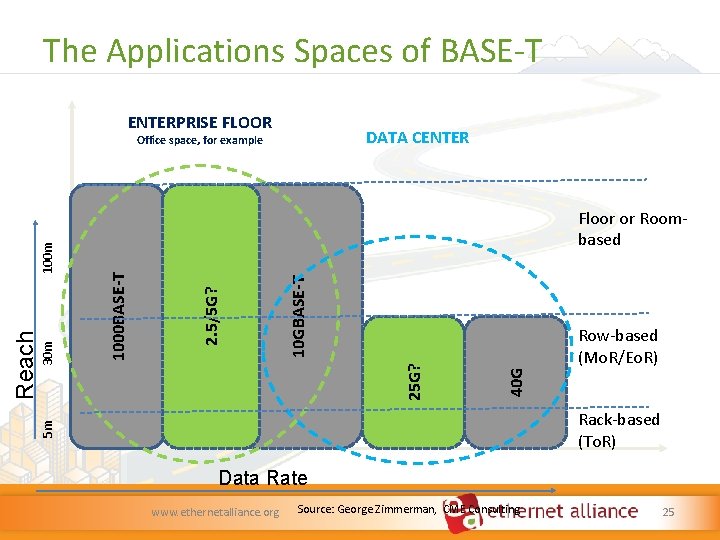
The Applications Spaces of BASE‐T ENTERPRISE FLOOR DATA CENTER Row‐based (Mo. R/Eo. R) 40 G 25 G? 10 GBASE-T 2. 5/5 G? 1000 BASE-T 30 m Floor or Room‐ based Rack‐based (To. R) 5 m Reach 100 m Office space, for example Data Rate www. ethernetalliance. org Source: George Zimmerman, CME Consulting 25
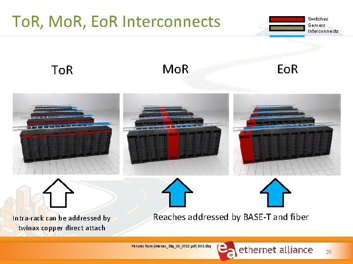
To. R, Mo. R, Eo. R Interconnects To. R Intra‐rack can be addressed by twinax copper direct attach Mo. R Switches Servers Interconnects Eo. R Reaches addressed by BASE‐T and fiber Pictures from jimenez_3 bq_01_0711. pdf, 802. 3 bq 26
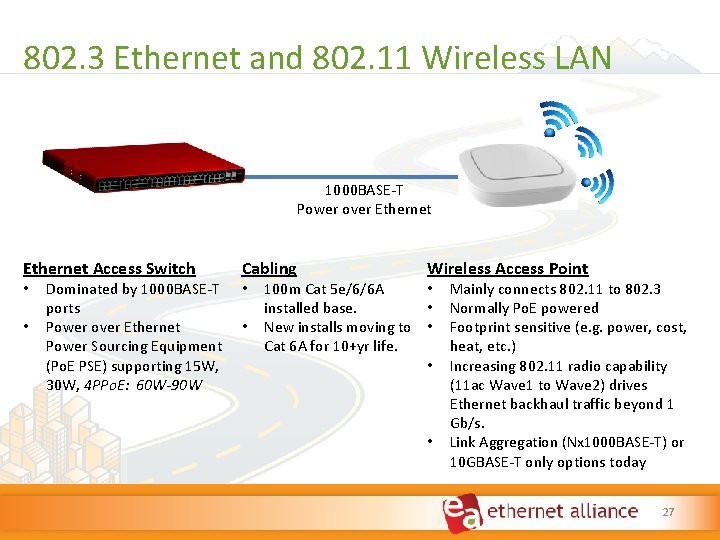
802. 3 Ethernet and 802. 11 Wireless LAN 1000 BASE‐T Power over Ethernet Access Switch Cabling • • • Dominated by 1000 BASE‐T ports Power over Ethernet Power Sourcing Equipment (Po. E PSE) supporting 15 W, 30 W, 4 PPo. E: 60 W-90 W • Wireless Access Point • 100 m Cat 5 e/6/6 A • installed base. New installs moving to • Cat 6 A for 10+yr life. • • Mainly connects 802. 11 to 802. 3 Normally Po. E powered Footprint sensitive (e. g. power, cost, heat, etc. ) Increasing 802. 11 radio capability (11 ac Wave 1 to Wave 2) drives Ethernet backhaul traffic beyond 1 Gb/s. Link Aggregation (Nx 1000 BASE‐T) or 10 GBASE‐T only options today 27
IMPLICATIONS OF 50 G SERDES ON ETHERNET SPEEDS Kapil Shrikhande www. ethernetalliance. org
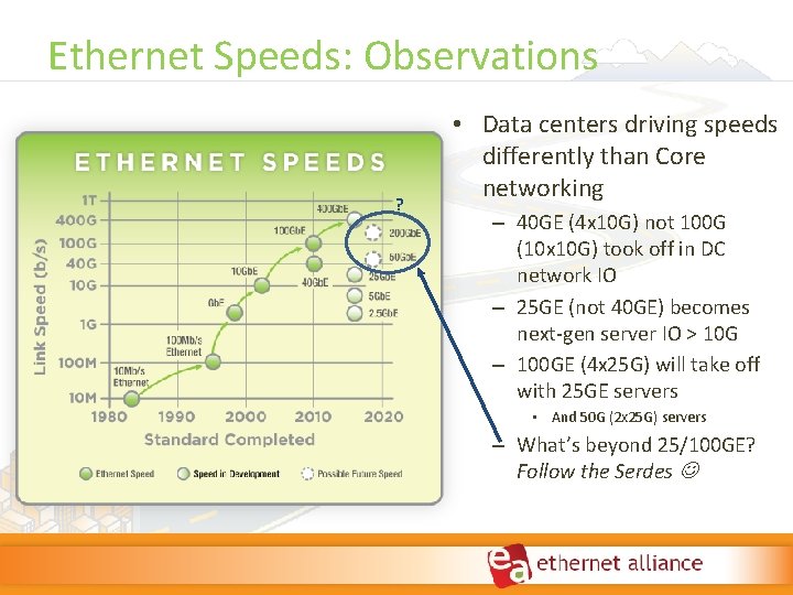
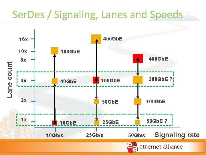
Ethernet Speeds: Observations ? • Data centers driving speeds differently than Core networking – 40 GE (4 x 10 G) not 100 G (10 x 10 G) took off in DC network IO – 25 GE (not 40 GE) becomes next‐gen server IO > 10 G – 100 GE (4 x 25 G) will take off with 25 GE servers • And 50 G (2 x 25 G) servers – What’s beyond 25/100 GE? Follow the Serdes
Ser. Des / Signaling, Lanes and Speeds 400 Gb. E 16 x Lane count 10 x 100 Gb. E 400 Gb. E 8 x 4 x 40 Gb. E 2 x 1 x 10 Gb. E 10 Gb/s 200 Gb. E ? 100 Gb. E 50 Gb. E 100 Gb. E 25 Gb. E 50 Gb. E ? 25 Gb/s 50 Gb/s Signaling rate
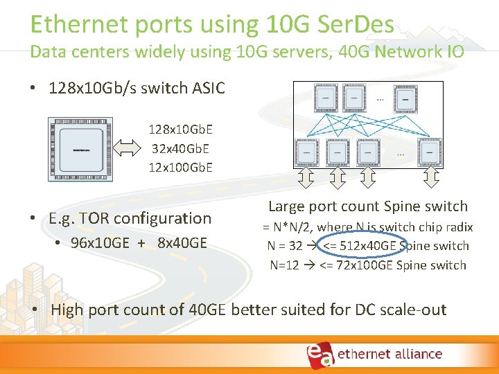
Ethernet ports using 10 G Ser. Des Data centers widely using 10 G servers, 40 G Network IO • 128 x 10 Gb/s switch ASIC 128 x 10 Gb. E 32 x 40 Gb. E 12 x 100 Gb. E • E. g. TOR configuration • 96 x 10 GE + 8 x 40 GE Large port count Spine switch = N*N/2, where N is switch chip radix N = 32 <= 512 x 40 GE Spine switch N=12 <= 72 x 100 GE Spine switch • High port count of 40 GE better suited for DC scale‐out
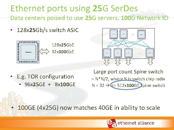
Ethernet ports using 25 G Ser. Des Data centers poised to use 25 G servers, 100 G Network IO • 128 x 25 Gb/s switch ASIC 128 x 25 Gb. E 32 x 100 Gb. E • E. g. TOR configuration • 96 x 25 GE + 8 x 100 GE Large port count Spine switch = N*N/2, where N is switch chip radix N = 32 <= 512 x 100 GE Spine switch • 100 GE (4 x 25 G) now matches 40 GE in ability to scale
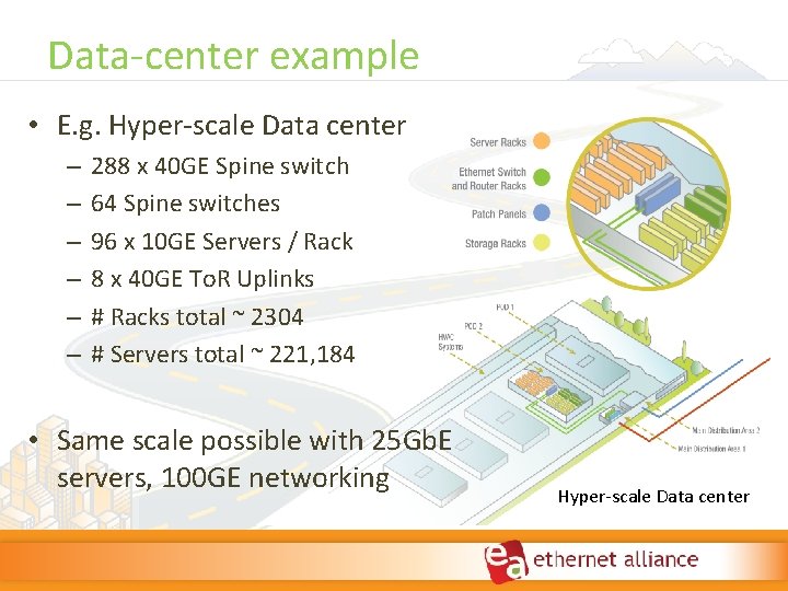
Data‐center example • E. g. Hyper‐scale Data center – – – 288 x 40 GE Spine switch 64 Spine switches 96 x 10 GE Servers / Rack 8 x 40 GE To. R Uplinks # Racks total ~ 2304 # Servers total ~ 221, 184 • Same scale possible with 25 Gb. E servers, 100 GE networking Hyper‐scale Data center
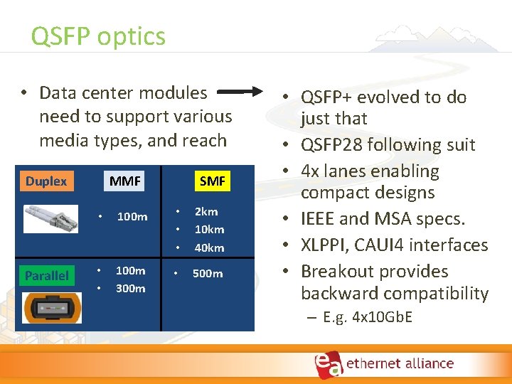
QSFP optics • Data center modules need to support various media types, and reach Duplex Parallel MMF SMF • 100 m • • • 2 km 10 km 40 km • • 100 m 300 m • 500 m • QSFP+ evolved to do just that • QSFP 28 following suit • 4 x lanes enabling compact designs • IEEE and MSA specs. • XLPPI, CAUI 4 interfaces • Breakout provides backward compatibility – E. g. 4 x 10 Gb. E
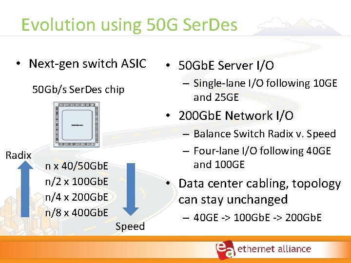
Evolution using 50 G Ser. Des • Next‐gen switch ASIC 50 Gb/s Ser. Des chip • 50 Gb. E Server I/O – Single‐lane I/O following 10 GE and 25 GE • 200 Gb. E Network I/O Radix • • n x 40/50 Gb. E n/2 x 100 Gb. E n/4 x 200 Gb. E n/8 x 400 Gb. E – Balance Switch Radix v. Speed – Four‐lane I/O following 40 GE and 100 GE • Data center cabling, topology can stay unchanged Speed – 40 GE ‐> 100 Gb. E ‐> 200 Gb. E
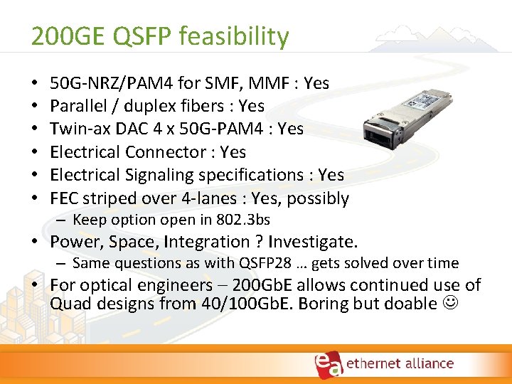
200 GE QSFP feasibility • • • 50 G‐NRZ/PAM 4 for SMF, MMF : Yes Parallel / duplex fibers : Yes Twin‐ax DAC 4 x 50 G‐PAM 4 : Yes Electrical Connector : Yes Electrical Signaling specifications : Yes FEC striped over 4‐lanes : Yes, possibly – Keep option open in 802. 3 bs • Power, Space, Integration ? Investigate. – Same questions as with QSFP 28 … gets solved over time • For optical engineers – 200 Gb. E allows continued use of Quad designs from 40/100 Gb. E. Boring but doable
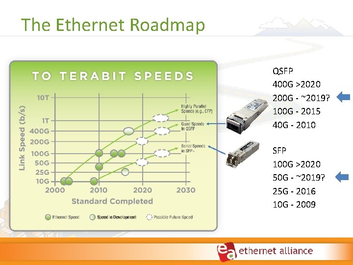
The Ethernet Roadmap QSFP 400 G >2020 200 G ‐ ~2019? 100 G ‐ 2015 40 G ‐ 2010 SFP 100 G >2020 50 G ‐ ~2019? 25 G ‐ 2016 10 G ‐ 2009
Questions and Answers
Thank You! If you have any questions or comments, please email admin@ethernetalliance. org Ethernet Alliance: visit www. ethernetalliance. org Join the Ethernet Alliance Linked. In group Follow @Ethernet. Allianc on Twitter Visit the Ethernet Alliance on Facebook