
The ESS Cryogenics System J G Weisend II


- Slides: 26
The ESS Cryogenics System J. G. Weisend II, P. Arnold, J Fydrych, W. Hees, J. Jurns, A. Lundmark, X. T. Su, X. L. Wang June 2015
Outline • Introduction to ESS • Applications of Cryogenics at ESS • Accelerator Cryoplant • Cryogenic Distribution System • Target Moderator Cryoplant • Test and Instruments Cryoplant • He Recovery and Storage • Energy Recovery • Summary June 2015 HEPTech - J. G. Weisend II 2
Introduction to ESS The goal of ESS is to provide a spallation based neutron source significantly more powerful than existing sources: 30 - 100 times brighter than ILL and 5 times more powerful than SNS This facility will enable neutron based research in a wide range of fields including: materials science, condensed matter and biomedical studies June 2015 HEPTech - J. G. Weisend II 3
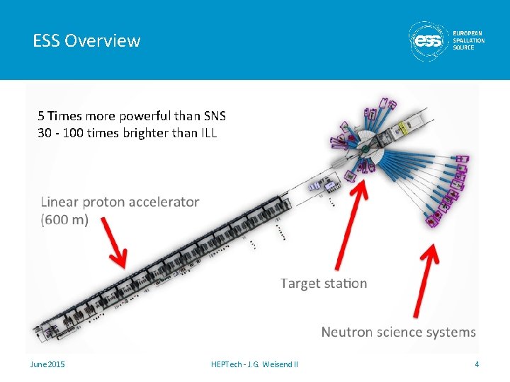
ESS Overview 5 Times more powerful than SNS 30 - 100 times brighter than ILL June 2015 HEPTech - J. G. Weisend II 4
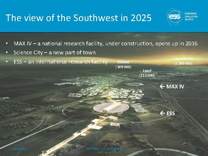
The view of the Southwest in 2025 • MAX IV – a national research facility, under construction, opens up in 2016 • Science City – a new part of town Copenhagen Malmö • ESS – an international research facility (1 200 000) (309 000) Lund (113 500) MAX IV ESS June 2015 HEPTech - J. G. Weisend II 5
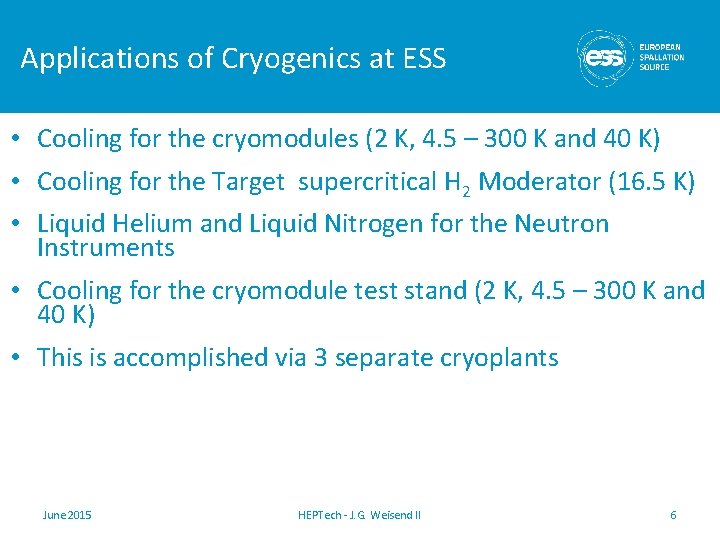
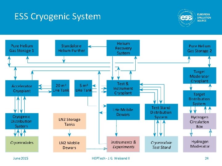
Applications of Cryogenics at ESS • Cooling for the cryomodules (2 K, 4. 5 – 300 K and 40 K) • Cooling for the Target supercritical H 2 Moderator (16. 5 K) • Liquid Helium and Liquid Nitrogen for the Neutron Instruments • Cooling for the cryomodule test stand (2 K, 4. 5 – 300 K and 40 K) • This is accomplished via 3 separate cryoplants June 2015 HEPTech - J. G. Weisend II 6
Accelerator Cryogenics • Bulk of acceleration is carried out via 3 classes of SRF cavities: Spoke, Medium (b = 0. 67 ) Beta Elliptical and High (b = 0. 86) Beta Elliptical • No superconducting magnets in the accelerator. There are some in the instruments • Cavities operate at 2 K with a 40 – 50 K thermal shield • Inner power coupler cooling from 4. 2 K to 300 K • Accelerator lattice permits an 14 additional cryomodules to compensate for lower than expected cryomodule gradients (Stage 2) June 2015 HEPTech - J. G. Weisend II 7
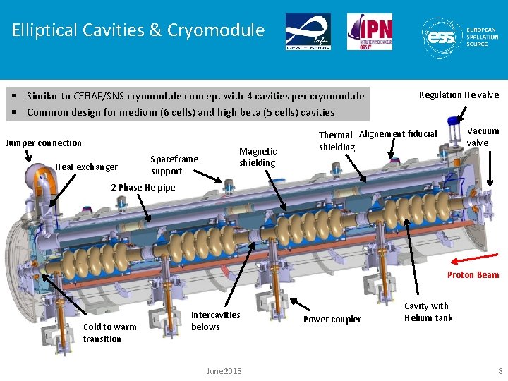
Elliptical Cavities & Cryomodule § Similar to CEBAF/SNS cryomodule concept with 4 cavities per cryomodule § Common design for medium (6 cells) and high beta (5 cells) cavities Jumper connection Heat exchanger Spaceframe support Magnetic shielding Regulation He valve Vacuum valve Thermal Alignement fiducial shielding 2 Phase He pipe Proton Beam Cold to warm transition Intercavities belows June 2015 Power coupler Cavity with Helium tank 8
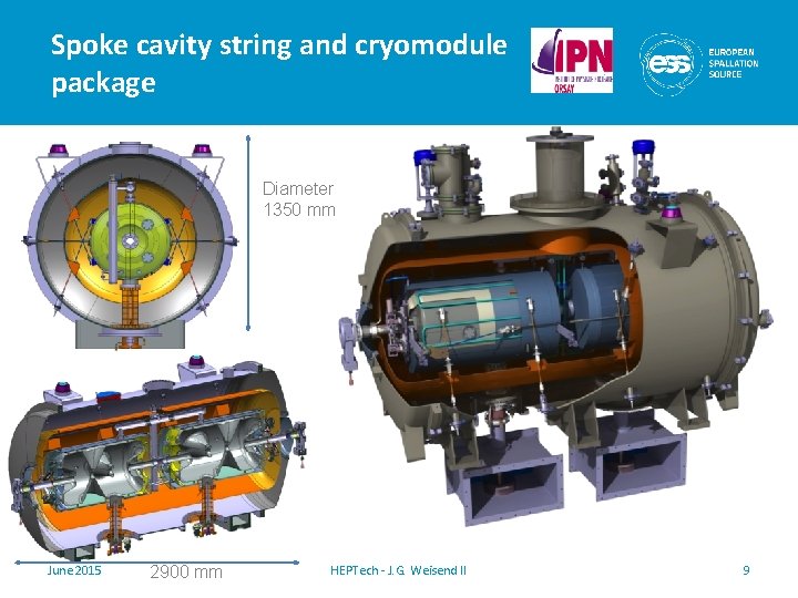
Spoke cavity string and cryomodule package Diameter 1350 mm June 2015 2900 mm HEPTech - J. G. Weisend II 9
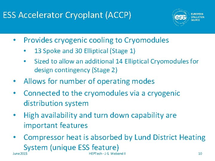
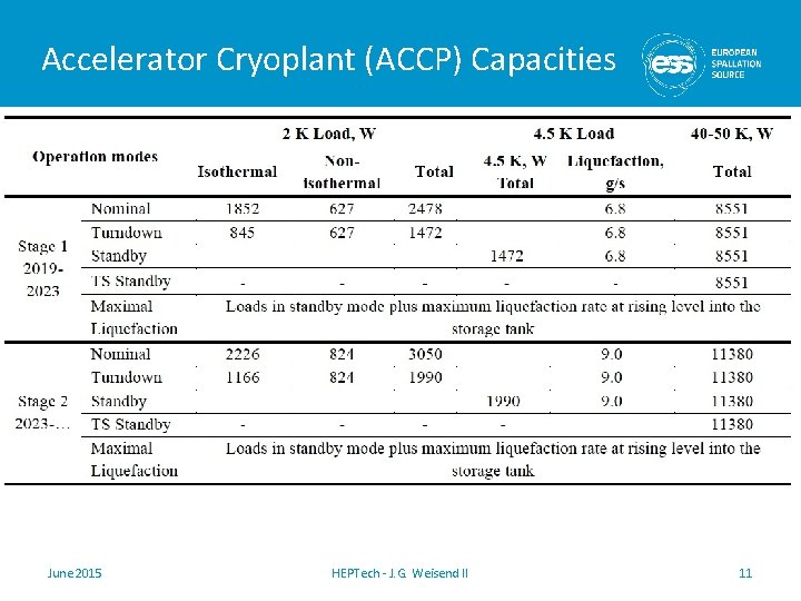
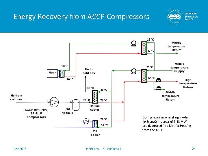
ESS Accelerator Cryoplant (ACCP) • Provides cryogenic cooling to Cryomodules • • 13 Spoke and 30 Elliptical (Stage 1) Sized to allow an additional 14 Elliptical Cryomodules for design contingency (Stage 2) • Allows for number of operating modes • Connected to the cryomodules via a cryogenic distribution system • High availability and turn down capability are important features • Compressor heat is absorbed by Lund District Heating System (unique ESS feature) June 2015 HEPTech - J. G. Weisend II 10
Accelerator Cryoplant (ACCP) Capacities June 2015 HEPTech - J. G. Weisend II 11
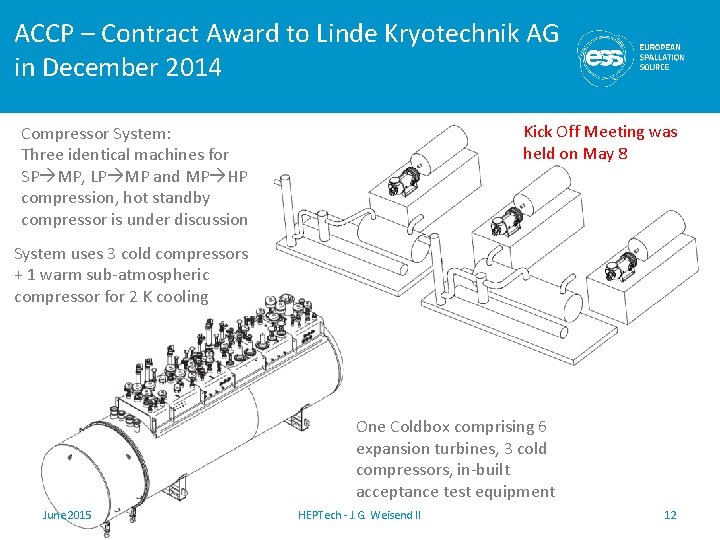
ACCP – Contract Award to Linde Kryotechnik AG in December 2014 Kick Off Meeting was held on May 8 Compressor System: Three identical machines for SP MP, LP MP and MP HP compression, hot standby compressor is under discussion System uses 3 cold compressors + 1 warm sub-atmospheric compressor for 2 K cooling One Coldbox comprising 6 expansion turbines, 3 cold compressors, in-built acceptance test equipment June 2015 HEPTech - J. G. Weisend II 12
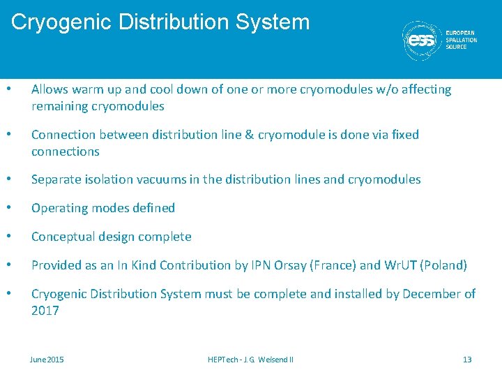
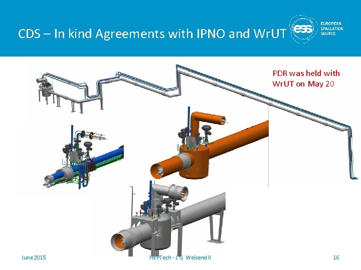
Cryogenic Distribution System • Allows warm up and cool down of one or more cryomodules w/o affecting remaining cryomodules • Connection between distribution line & cryomodule is done via fixed connections • Separate isolation vacuums in the distribution lines and cryomodules • Operating modes defined • Conceptual design complete • Provided as an In Kind Contribution by IPN Orsay (France) and Wr. UT (Poland) • Cryogenic Distribution System must be complete and installed by December of 2017 June 2015 HEPTech - J. G. Weisend II 13
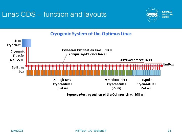
Linac CDS – function and layouts Cryogenic System of the Optimus Linac Cryoplant Cryogenic Transfer Line (75 m) Cryogenic Distribution Line (310 m) comprising 43 valve boxes Auxiliary process lines Splitting box 21 High Beta Cryomodules (174 m) 9 Medium Beta Cryomodules (75 m) Endbox 13 Spoke Cryomodules (54 m) Superconducting section of the Optimus Linac (303 m) June 2015 HEPTech - J. G. Weisend II 14
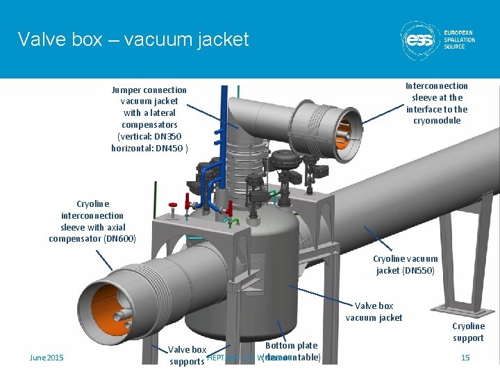
Valve box – vacuum jacket Interconnection sleeve at the interface to the cryomodule Jumper connection vacuum jacket with a lateral compensators (vertical: DN 350 horizontal: DN 450 ) Cryoline interconnection sleeve with axial compensator (DN 600) Cryoline vacuum jacket (DN 550) Valve box vacuum jacket June 2015 Bottom plate Valve box II (demountable) supports HEPTech - J. G. Weisend Cryoline support 15
CDS – In kind Agreements with IPNO and Wr. UT PDR was held with Wr. UT on May 20 June 2015 HEPTech - J. G. Weisend II 16
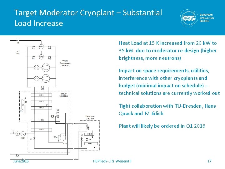
Target Moderator Cryoplant – Substantial Load Increase Heat Load at 15 K increased from 20 k. W to 35 k. W due to moderator re-design (higher brightness, more neutrons) Impact on space requirements, utilities, interference with other cryoplants and budget (minimal impact on schedule) – technical solutions are currently worked out Tight collaboration with TU-Dresden, Hans Quack and FZ Jülich Plant will likely be ordered in Q 1 2016 June 2015 HEPTech - J. G. Weisend II 17
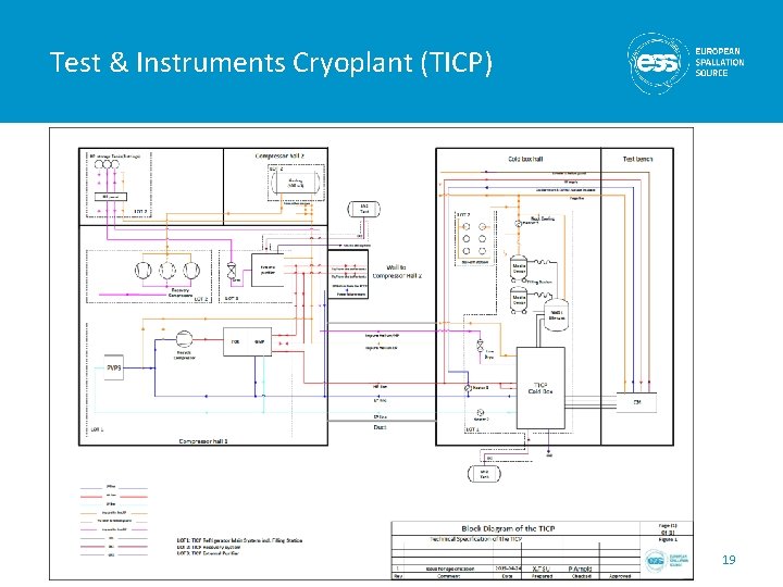
Test & Instruments Cryoplant (TICP) • Provides cooling for Cryomodule Test Stand • During Science Operations, also provides LHe for sample environments and Science Instruments • TICP provides for CM testing: 76 W at 2 K, 422 W at 40 K and 0. 2 g/s of liquid helium • Sub-atmospheric operation via warm vacuum pumps • During Science Operations, the TICP shall provide more than 7500 liters of LHe per month • A recovery system is being built to recover all He gas from instrument halls and return it for purification and liquefaction. • We expect to order this plant in Q 4 2015 June 2015 HEPTech - J. G. Weisend II 18
Test & Instruments Cryoplant (TICP) June 2015 HEPTech - J. G. Weisend II 19
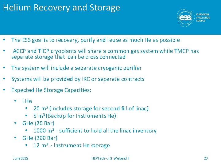
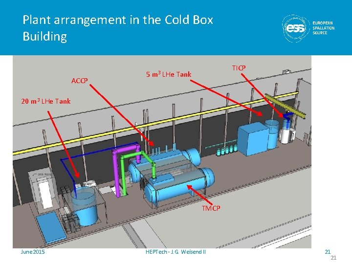
Helium Recovery and Storage • The ESS goal is to recovery, purify and reuse as much He as possible • ACCP and TICP cryoplants will share a common gas system while TMCP has separate storage that can be cross connected • The system will include a separate cryogenic purifier • Systems will be provided by IKC or separate contracts • Expected He Storage Capacities: • LHe • 20 m 3 (Includes storage for second fill of linac) • 5 m 3 (Backup for Instruments He) • GHe (20 Bar) • 1000 m 3 - sufficient to hold all the linac inventory • GHe (200 Bar) • 12 m 3 - Instrument He storage June 2015 HEPTech - J. G. Weisend II 20
Plant arrangement in the Cold Box Building ACCP 5 m 3 TICP LHe Tank 20 m 3 LHe Tank TMCP June 2015 HEPTech - J. G. Weisend II 21 21
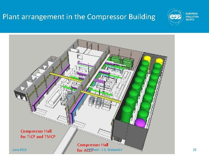
Plant arrangement in the Compressor Building Compressor Hall for TICP and TMCP June 2015 Compressor Hall HEPTech - J. G. Weisend II for ACCP 22
Energy Recovery from ACCP Compressors During nominal operating mode in Stage 2 – a total of 2. 48 MW are deposited into District Heating from the ACCP June 2015 HEPTech - J. G. Weisend II 23
ESS Cryogenic System June 2015 HEPTech - J. G. Weisend II 24
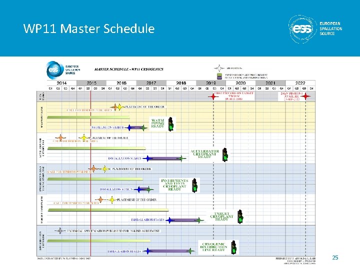
WP 11 Master Schedule 25
Summary • Cryogenics will play a major role in ESS and affects the accelerator, target and instruments projects • Work is well underway • A very skilled team has been assembled • Conceptual designs and technical specifications are complete or under preparation • Required buildings and utilities have been defined and are under detailed design • Accelerator Cryoplant order has been placed (Kick off meeting was held on May 8) • PDR for the Wr. UT portion of the CDS was held on May 2015 • Additional cryoplant orders will be placed in late 2015 and early 2016 June 2015 HEPTech - J. G. Weisend II 26