the dynamics of convection 1 Cumulus cloud dynamics


- Slides: 28

the dynamics of convection 1. Cumulus cloud dynamics • The basic forces affecting a cumulus cloud – – buoyancy (B) buoyancy-induced pressure perturbation gradient acceleration (BPPGA) dynamic sources of pressure perturbations entrainment: Simple models of entraining cumulus convection (E) Suggested readings: M&R Section 2. 5: pressure perturbations Bluestein (Synoptic-Dynamic Met Pt II, 1993) Part III Houze (Cloud Dynamics, 1993), Chapter 7 Holton (Dynamic Met, 2004) sections 9. 5 and 9. 6 Cotton and Anthes (Storm and Cloud Dynamics, 1982) Emanuel (Atmospheric Convection, 1994)

Essential Role of Convection • You have learned about the role of baroclinic systems in the atmosphere: they transport sensible heat and water vapor poleward, offsetting a meridional imbalance in net radiation. • Similarly, thermal convection plays an essential role in the vertical transport of heat in the troposphere: – the vertical temperature gradient that results from radiative equilibrium exceeds that for static instability, at least in some regions on earth.

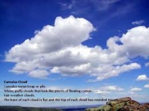
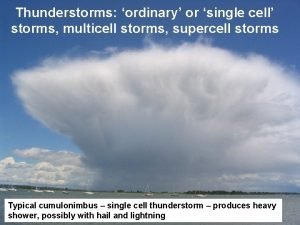
Cumulus Clouds • Range in size from – – – cumuli (less than 1000 m in 3 D diameter) congesti (~1 km wide, topping near 4 -5 km) cumulonimbus clouds (~10 km) to thunderstorm clusters (~100 km) to mesoscale convective complexes (~500 km). topping near the tropopause • • All are ab initio driven by buoyancy B vertical equation of motion: PPGF • buoyancy force PPGF: pressure perturbation gradient force

buoyancy: we derive buoyancy from vertical momentum conservation equation vertical equation of motion, non-hydrostatic basic state is hydrostatically balanced terms cancel small term define buoyancy B:

scaling the buoyancy force • Complete expression for buoyancy: see (Houze p. 36) where qh is the mixing ratio of condensed-phase water (‘hydrometeor loading’). In terms of its effect on buoyancy (Bq/g), 1 K of excess heat q‘ is equivalent to. . . 5 -6 g/kg of water vapor (positive buoyancy). . . 3 -4 mb of pressure deficit (positive buoyancy). . . 3. 3 g/kg of water loading (negative buoyancy) This shows that q’ dominates. All other effects can be significant under some conditions in cumulus clouds.

buoyancy: outside of cloud, buoyancy is proportional to the virtual pot temp perturbation

The buoyancy force • To a first order, the maximum updraft speed can be estimated from sounding-inferred CAPE: this ignores effect of water vapor (+B) and the weight of hydrometeors (-B). w= sqrt(2 CAPE) is thermodynamic updraft strength limit This updraft speed is a vast over-estimate, mainly b/o two opposing forces. • pressure perturbations: Buoyancy-induced (or ‘convective’) ascent of an air parcel • entrainment disrupts the ambient air. On top of a rising parcel, you ‘d expect a high (i. e. a positive pressure perturbation), simply because that rising parcel pushes into its surroundings. The resulting ‘perturbation’ pressure gradient enables compensating lateral and downward displacement as the parcel rises thru the fluid. Solutions show the compensating motions decaying away from the cloud, concentrated within about one cloud diameter.

this pressure field contains both a hydrostatic and a non-hydrostatic component B>0 B<0 Fig. 2. 2 in M&R

discuss pressure changes in a hydrostatic atmosphere (M&R 2. 6. 1) • mass conservation: – pressure tendency = vertically integrated mass divergence • hypsometric eqn: – pressure tendency = vertically integrated temperature change

2 nd force: pressure perturbation gradient acceleration (PPGA) (M&R section 2. 6. 3) anelastic continuity eqn FB: buoyancy source tensor notation FD: dynamic source ** These equations are fundamental to understand the dynamics of convection, ranging from shallow cumuli to isolated thunderstorms to supercells. For now we focus on FB. Later, we ‘ll show that FD is essential to understand storm splitting and storm motion aberrations.

It can be shown that Also, p’D> 0 (a high H) on the upshear side of a convective updraft, and p’D< 0 (a low L) on the downshear side

the buoyancy-induced pressure perturbation gradient acceleration (BPPGA): z x Shaded area is buoyant B>0 Analyze: This is like the Poisson eqn in electrostatics, with FB the charge density, p’B the electric potential, and p’B show the electric field lines. The + and – signs indicate highs and lows: where L is the width of the buoyant parcel

Where p. B>0 (high), 2 p. B <0, thus the divergence of [- p. B] is positive, i. e. the BPPGA diverges the flow, like the electric field. The lines are streamlines of BPPGA, the arrows indicate the direction of acceleration. Within the buoyant parcel, the BPPGA always opposes the buoyancy, thus the parcel’s upward acceleration is reduced. A given amount of B produces a larger net upward acceleration in a smaller parcel for a very wide parcel, BPPGA=B (i. e. the parcel, though buoyant, is hydrostatically balanced) (in this case the buoyancy source equals d 2 p’/dz 2)

(10 km) t=13 min (3 km) t=8 min H H L L L Fig. 3. 1 in M&R (no entrainment)

pressure field in a density current (M&R, Fig. 2. 6) L H H pressure units: (Pa) L H H L L H H interpretation: use Bernoulli eqn along a streamline Note that p’ = p’h+p’nh = p’B+p’D p’h is obtained from p’B is obtained by solving p’D = p’-p’B and p’nh = p’-p’h with at top and bottom.

pressure field in a cumulus cloud (M&R, Fig. 2. 7) H pressure units: (Pa) 2 K bubble, radius = 5 km, depth 1. 5 km, released near ground in environment with CAPE=2200 J/kg. Fields shown at t=10 min L Note that p’ = p’h+p’nh = p’B+p’D L p’h is obtained from and p’nh = p’-p’h H p’B is obtained by solving L L with H H L H p’D = p’-p’B at top and bottom.

Third force (also holding back buoyancy): entrainment • entrainment does two things: • No elegant mathematical formulation exists for entrainment E. The reason is that we are entering the realm of turbulence. We are reduced to some simple conceptual models of cumulus convection. • (a) both the upward momentum and the buoyancy of a parcel are dissipated by mixing (b) cloudy air is mixed with ambient dry air, causing evaporation – – Thermals or Bubbles Plumes or Jets A general expression for the vertical momentum eqn for continuous, homogenous entrainment (Houze p. 227 -230) (1 D, steady state) is: (assumed) simplify to 1 D, steady state & solve

effect of entrainment on a skew T-log p diagram M&R Figure 3. 2. A possible trajectory (dashed) that might be followed by an updraft parcel on a skew T-log p diagram as a result of the entrainment of environmental air.

Thermals or Bubbles • Laboratory studies • negatively buoyant, dyed parcels are released, with small density difference relative to the environmental fluid • basic circulations look like this: The thermal grows as air is entrained into thermal, via: • turbulent mixing at the leading edge; • laminar flow into the tail of thermal At first vorticity is distributed throughout thermal. Later it becomes concentrated in a vortex ring. Results: shape oblate, nearly spherical; volume=3 R 3

• • • note shear instability along leading boundary entrainment rate seems small at first undilute core persists for some time, developing into a vortex ring Sanchez et al 1989

Cumulus bubble observation Example of a growing cu on Aug. 26 th, 2003 over Laramie. Two-dimensional velocity field overlaid on filled contours of reflectivity (Z [d. BZ]); solid lines are selected streamlines. (source: Rick Damiani)

Cumulus bubble observation d. BZ 20030826, 18: 23 UTC 8 m/s • Two counter-rotating vortices are visible in the ascending cloud-top. • They are a cross-section thru a vortex ring, aka a toroidal circulation (‘smoke ring’) (Damiani et al. , 2006, JAS)

2. 6 sounding analysis • CAPE • CIN • DCAPE (D for downdraft) implications: * use Tv (not T) to compute CAPE/CIN * plot Tv (not T) in soundings

2. 7 hodographs • • total wind vh shear vector S storm motion c storm-relative wind vr = vh-c S vh storm-relative flow vr c height AGL (km)

2. 7. 5 true & storm-relative wind near a supercell storm c real example (M&R, Fig. 2. 14) M&R, Fig. 2. 13: hypothetical profiles: different wind vh, but identical vr

2. 7. 6 horizontal vorticity storm-relative flow horizontal vorticity

• streamwise vorticity • cross-wise cro ise str eam wis e ss-w note error in book error

definition of helicity (Lilly 1979) • the top is usually 2 or 3 km (low level !) • H is maximized by high wind shear NORMAL to the stormrelative flow – strong directional shear • H is large in winter storms too, but static instability is missing storm-relative flow horizontal vorticity
 3 basic types of clouds
 Awan cumulus nimbus
 Bill nye severe weather
 Bounded weak echo region
 Cumulus clouds in oral pathology
 Three main types of clouds
 Shallow cumulus
 Pt weather chart
 Describe clouds
 Cumulus stage
 Towering cumulus stage
 Cumulus co
 Mean
Mean Awan stratus
 Cirrus stratus cumulus cumulonimbus clouds
 Type of cloud
 Cumulus stage
 Cumulus
 Stratus cumulus
 How do cumulonimbus clouds form
 Segala macam bentuk
 Single cell thunderstorm
 Nimbus stratus
 Cumulus clouds
 Cumulus mature dissipating
 Chapter 18 moisture clouds and precipitation
 Lepsnap
 A composable component must be modular
 Cloud integration patterns
