
The Duality between Planar Kinematics and Statics Dr
The Duality between Planar Kinematics and Statics Dr. Shai, Tel-Aviv, Israel Prof. Pennock, Purdue University
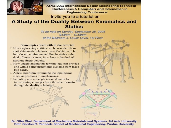

The Outline for the tutorial: A Study of the Duality between Kinematics and Statics • Two new concepts for statics that are derived from kinematics: Equimomental line and face force. • Transforming theorems and rules between kinematics and statics. • Characterizing and finding dead center positions of mechanisms and the stability of determinate trusses. • Correlation between Instant Centers and Equimomental Lines. • Graph theory duality principal and the dual of linkages – trusses. • Detailed example of the face force and the procedure for deriving the face force. • Transforming Stewart platforms into serial robots and vice versa. • Checking singularity through the duality transformation. • Applying the duality transformation for systematic conceptual design. • Discussion and suggestion for future research in this area
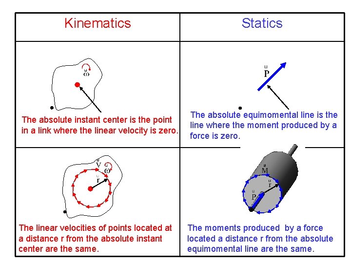
Kinematics Statics The absolute instant center is the point in a link where the linear velocity is zero. The absolute equimomental line is the line where the moment produced by a force is zero. The linear velocities of points located at a distance r from the absolute instant center are the same. The moments produced by a force located a distance r from the absolute equimomental line are the same.
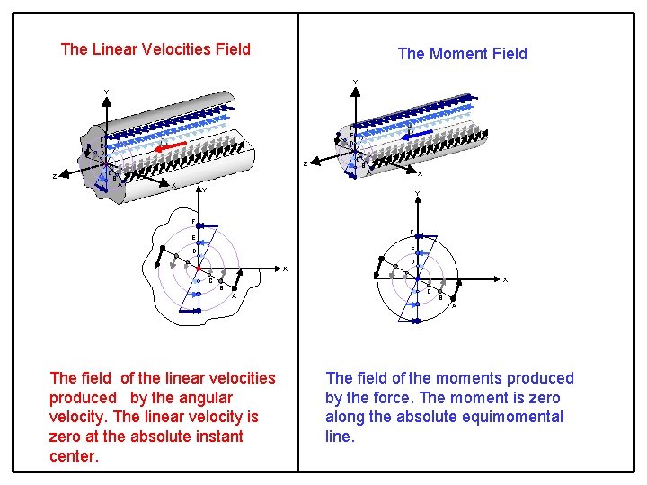
The Linear Velocities Field The Moment Field Y Y F E D Z Z C B A X Y Y F F E E D X C B A The field of the linear velocities produced by the angular velocity. The linear velocity is zero at the absolute instant center. The field of the moments produced by the force. The moment is zero along the absolute equimomental line.
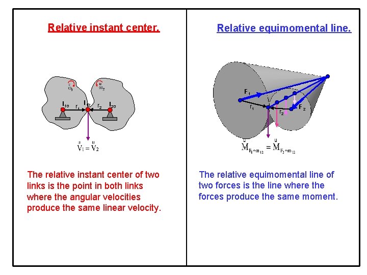
Relative instant center. Relative equimomental line. F 1 I 10 r 1 I 12 r 2 I 20 The relative instant center of two links is the point in both links where the angular velocities produce the same linear velocity. r 1 r 2 F 2 The relative equimomental line of two forces is the line where the forces produce the same moment.
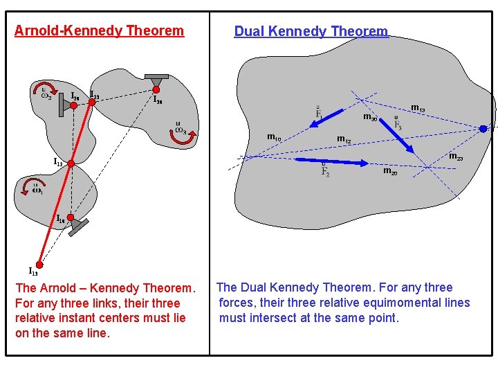
Arnold-Kennedy Theorem I 20 I 23 Dual Kennedy Theorem I 30 m 13 m 30 m 10 I 12 m 23 m 20 I 13 The Arnold – Kennedy Theorem. For any three links, their three relative instant centers must lie on the same line. The Dual Kennedy Theorem. For any three forces, their three relative equimomental lines must intersect at the same point.
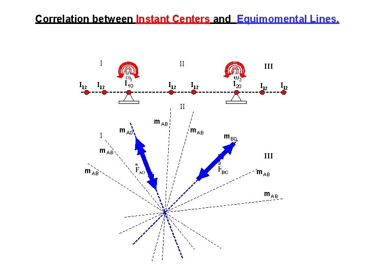
Correlation between Instant Centers and Equimomental Lines. I I 12 II I 10 I 12 III I 12 I 20 I 12 II I m. AB m. A 0 m. AB m. B 0 III m. AB I 12
The idea behind the transformation of Kinematic systems (Linkages) into Static systems (determinate trusses) • Each engineering system can be represented into mathematical model based on graph theory. • There are mathematical relations between the graph representations such as the graph theory duality. • For example, the representations of linkages and trusses were found to be dual. Thus, linkages and determinate trusses are dual systems. The following slides will show the process of constructing dual engineering systems on the basis of the graph theory duality principle.
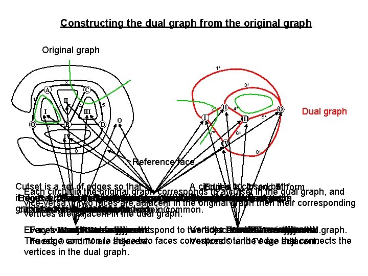
Constructing the dual graph from the original graph Original graph 1* 3 A 1 2 II 5 4 I O 3* C 2* III 7 B 6 D II 4* I O 5* III 7* IV O Dual graph 6* IV 8 8* Reference face. Cutset is a set of edges so that A circuit is 1*, a closed Edges 3*, 4* andpath. 2* 5* form 7* Each circuit in the original graph corresponds to a cutset in the dual graph, and if. Edges removed the graph, the Face IV I corresponds II III corresponds tototowithout the vertex II. IV. a circle cutset inin dual graph. Aand face in the graph isgraph aadjacent circuit inner edges. Each in faces the corresponds to athen vertex Reference face Ograph corresponds toto. I. graph the Each 3, 1, 4 2 from cutset 5 7 face in constitute Two the original aadjacent are corresponds ifthe they have a at circuit in their the corresponding vice-versa. If two faces areoriginal in the original graph becomes disconnected. in original the dual graph. reference vertex O. cutset circuit dual in the graph, and least graph. vice versa. edge common. vertices are adjacent inone the dual in graph. Vertices II I and IV are adjacent. Every adjacent faces correspond to two adjacent vertices in the dual graph. Facestwo III Oand III and. IV IIO III IIV are are adjacent. O III and IIO III IIV are are adjacent. The edge to adjacent. these two faces corresponds the. IVedge that connects the Faces O common and IV are Vertices O to and are adjacent. vertices in the dual graph.
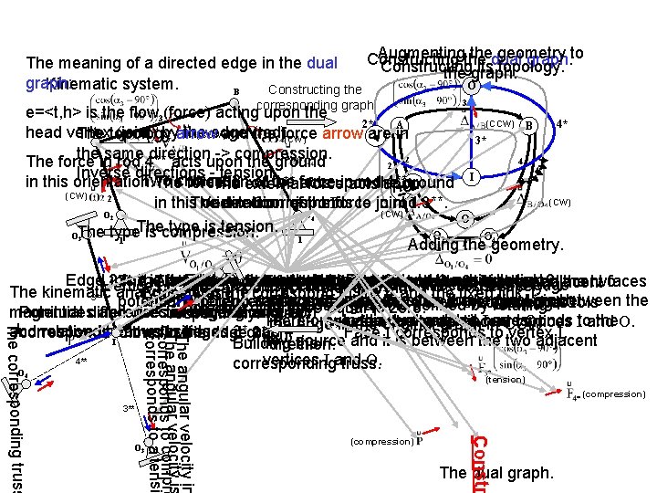
Augmentingthe thedual geometry Constructing graph. to The meaning of a directed edge in the dual Constructing its topology. the graph: O Kinematic system. Constructing the B corresponding graph 3 e=<t, h> is the flow 3(force) acting upon the (CCW) B 2* 4* A A head vertex (joint) byarrow the edge (CCW) The topology and (rod). the force arrow are in (CW) 3* the same direction -> compression. 2 4 The force in rod 4** acts upon the ground 2 4 Inverse directions - tension 4 I Two in this orientation. direction of the inacts rodthe 4**. Thechoices? force in external rod 3** force acts upon ground The force upon (CW) 2 (CW) in this. The orientation. Vertex I corresponds to joint direction ofjoint the. Iforce in rod. I. 3**. (CW) O O O The type is tension. OThe type is compression. O 2 O 4 1 1 1 the geometry. Adding 2 4 3 O 3 source Vertex O to Faces joint O. and Othe adjacent. Edge. Link 2 The is 2 the is potential the Edge driving corresponds link. that corresponds to link 3. to driving link 2. the twofaces Vertex A corresponds The potential to joint source, 4 is A. the edge 2, relative The relative velocity velocities linear of of link velocity links 2 to corresponds 3 corresponds and 4 to. Othe to the Edge 3 common to is the two adjacent 24 corresponds 2 Icorrespond For consistency, direction ofbetween the edge Vertices B and O correspond joints B and , are respectively. We can contract the edges with 4 The kinematic analysis yields the Edges 4 and 1 correspond to link 4 and the fixed link 1, 3** adjacent Iequal faces and O Iand thus Othe in dual the original edge 4* graph. is between the potential differences potential of difference. ofedges 2. 3 Reference and 4. 4**to the faces Ito O thus the dual edge 3* face O corresponds to is in the dual graph is defined by rotating potential difference zero. magnitudes and directions of the angular Potential differences in edges 3 and 4 of the edge original 2 Therefore, graph twoinadjacent respectively. vertices and O. theoriginal dual graph it Icorresponds the. O. between the vertex two adjacent vertices Itoand reference O. the edge in. Face the graph in CCW and relative linear velocities. correspond to. Itoflows in edges 3*graph. and 4*. corresponds the flow the in edge dual 2*. I corresponds to vertex I. flow source and it is between the two adjacent Building the direction. 4** vertices I and O. corresponding truss. 4 3** O 3 (tension) (compression) Constr ity in The angular velocity e angular veloc is Th corresponds to compre corresponds to a tensi The corresponding truss O 4 The dual graph.
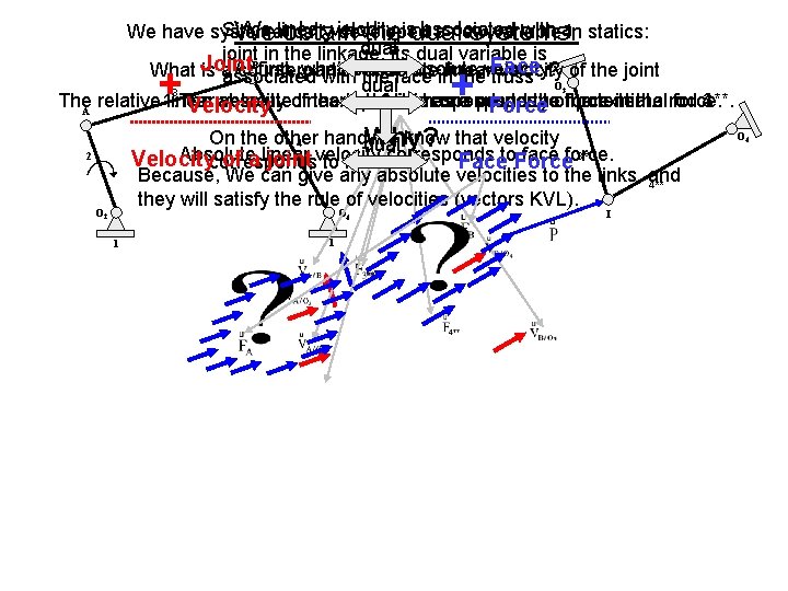
Since velocity associated with ain statics: We have systematically developed a new variable We linear obtain theisdual systems. dualits dual variable is joint. B in the linkage, Face At first, what isthe thisface absolute velocity? What Joint is a counterpart to absolute linear velocity of the joint associated with in the truss O dual 3 The. A relative 1. The linear velocity oflinear the link input 3 link 4 corresponds to the toofthe force external in the rod force. 3**. 4**. absolute velocity has a property potential. Velocity Force + + 3 On the other handdual we know that velocity Why? 4 3** Absolute linear velocity face force. Velocitycorresponds of a joint to force. corresponds Faceto. Force Because, We can give any absolute velocities to the links, and 4** they will satisfy the rule of velocities (vectors KVL). 2 O 4 1 1 I O 4
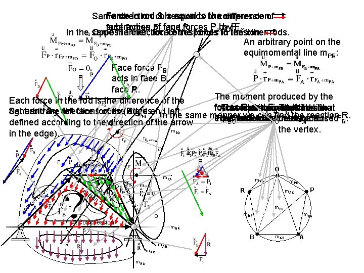
2 1 is equal to to Same direction Force in rod corresponds 3 thecompression. difference of subtraction of. A face forces P F by by. FFAO. . face forces F and F. In the same manner, locate the. B forces. A to in tension. the other rods. Opposite direction corresponds An arbitrary point on the equimomental line m. PA PB: Face force FBAP acts in face the B. face A. P. The moment produced by the Each force in the rod is the difference of the forces P and FBA The on the upon the line Absolute circuit equimomental corresponds circuit to The equimomental lines that Set of the(Right edges. rightarbitrary and the directions left face forces and left m In the same manner weobtain can find the reaction R. Thus we the face force F. equimomental line m. m the vertex. has to be corresponds determined. to will locate m. m B PB A PA BO BO defined according to the direction of the arrow the vertex. m in the edge). PB PO BO P compression O 2 1 n ssio B 3 m. RO m. PO R pre m co com sio n e pr A ten n io ss 4 m. PA P m. AO m. PB m. BR O compression m. PA m. BR 5 B R m. AO m. RO m. AB A
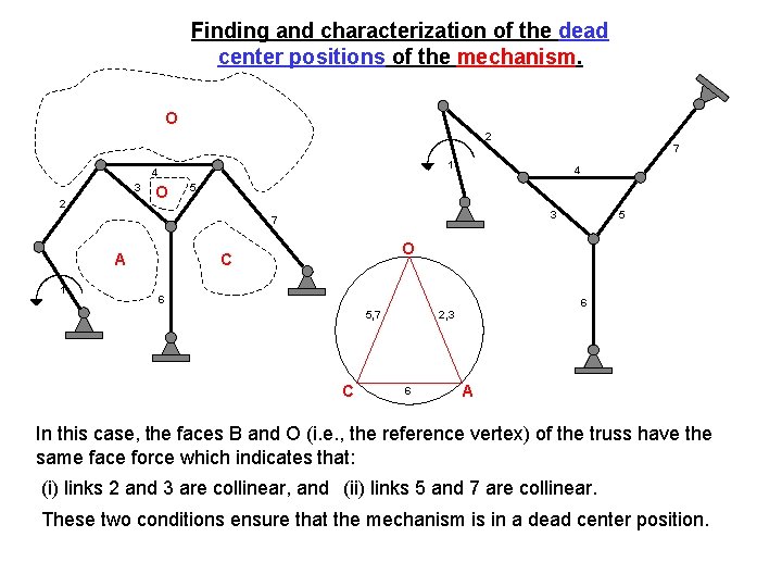
Finding and characterization of the dead center positions of the mechanism. O 2 7 1 4 3 2 O 4 5 A 1 5 3 7 O C 6 2, 3 5, 7 6 A In this case, the faces B and O (i. e. , the reference vertex) of the truss have the same face force which indicates that: (i) links 2 and 3 are collinear, and (ii) links 5 and 7 are collinear. These two conditions ensure that the mechanism is in a dead center position.
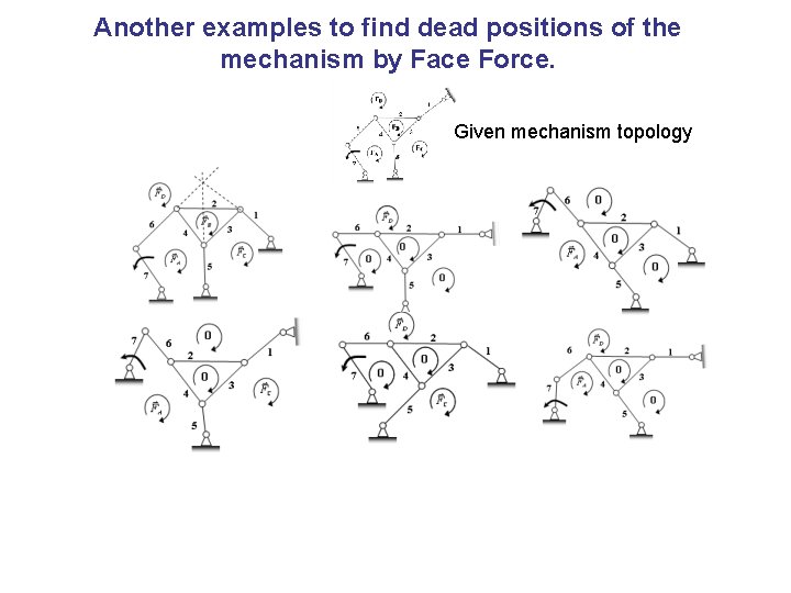
Another examples to find dead positions of the mechanism by Face Force. Given mechanism topology
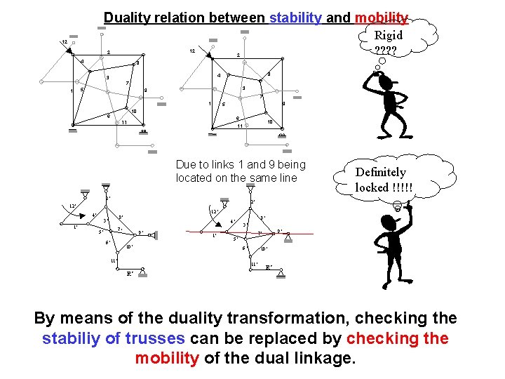
Duality relation between stability and mobility Rigid ? ? 12 12 2 4 8 4 3 7 5 1 2 8 3 9 7 1 9 5 10 6 6 11 10 11 Due to links 1 and 9 being located on the same line 2’ 2’ 12’ 4’ 12’ 8’ 3’ 1’ Definitely locked !!!!! 4’ 7’ 5’ 6’ 9’ 10’ 11’ 1’ 8’ 3’ 6’ 10’ 11’ R’ 9’ 7’ 5’ R’ By means of the duality transformation, checking the stabiliy of trusses can be replaced by checking the mobility of the dual linkage.
- Slides: 16