The Development of Plunger Device for Lifetime Measurements


 Structure design and precise")
Guarantee the")


Smooth surface of the target and stopper 2)Parallel")


Precision 2)Stability 3)Robustness When the range")


Realize the precise motion 2)The shifted and stopped spectrum are obvious 1)No closed loop")
 Improve the precision to measure the distance")

- Slides: 23
The Development of Plunger Device for Lifetime Measurements in CIAE By: In-beam Gamma Group Tutor: Xiao. Guang Wu Reported By: Jin. Long Wang 2012 4@Hu. Zhou
Contents 1 2 3 The Basis of The Plunger 1. 1 The Background 1. 2 Principle The Latest Work and Development 2. 1 Structure design and precise motion 2. 2 Flatten the foils 2. 3 Capacitance to measure the distance 2. 4 Closed cycle control Summary and Next Work 3. 1 The test experiment and result 3. 2 The work on calendar
1 The Basis of The Plunger 1. 1 The Background HOT Nuclear Chirality Lifetime B(E 2), B(M 1) HOT Nuclear phase transition X(5) E(5) Neutron rich nucleus For the long run
Measurement of short nuclear lifetimes High-spin state lifetimes are around ps Doppler-shift Attenuation Method Range: 10 -14 -10 -12 s AM S D RD DS Recoil distance Doppler-shift Method Ranger: 10 -12 -10 -9 s PLUNGER
1. 2 Principle Köln Plunger, Supplied in GSI, RIKEN,NSCL/MSU,GANIL, JYFL
2 The Latest Work and Development Main Technical Difficulties 1) Structure design and precise motion N-861 2) Flatten the foils TH 2822 C 3) Capacitance to measure the distance 4) Closed cycle control PLUNGER PC N-661 The Test System Components
2. 1 Structure design and precise motion Structure design by CAD Requirements: 1)Guarantee the motion in our chamber 2)Guarantee the vacuum 3)Guarantee the parallelism of the target and the stopper 4)Guarantee the stability 5) Under 1)-4) should be simple and light
The kinematic simulation
The vacuum and motion test With the base, all the parts in the chamber, have the control system. 9: 12 9: 16 9: 30 10: 15 11: 18 11: 35 Mechanical pump start Molecule pump start 2. 9*10 -3 Pa Move Stage 7. 8*10 -4 Pa 5. 1*10 -4 Pa Move stage About 2 h the vacuum got up to the request, which confirms the vacuum-sealing is OK. Moving the stage has no impact on the vacuum. 12: 53 12: 57 13: 03 13: 26 14: 00 14: 18 Mechanical pump start Molecule pump start 2. 0*10 -3 Pa Move Stage 7. 0*10 -4 Pa 5. 1*10 -4 Pa 4. 7*10 -4 Pa Move stage About 1 h the vacuum got up to the request, which confirms the vacuum-sealing is GOOD. Moving the stage has no impact on the vacuum. Other tests: Mechanical shock test, stability test combine with the software
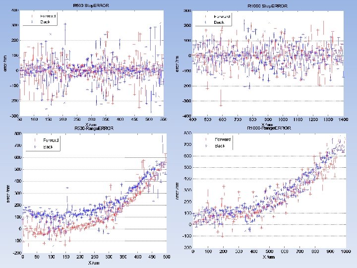
2. 1 Precise motion The precise requirement: Range 0 -200 um Error<0. 1 um Range 200 -20000 um Relative error<1% Error Proportion <100 nm 100~200 nm 90% 9% >200 nm 1%
2. 3 Flatten the foils Requirements: 1)Smooth surface of the target and stopper 2)Parallel between the target and stopper 3 mg/cc 2 mg/cc
The FEM simulation
2. 3 Capacitance to measure the distance Requirements: measure the distance at a precision better than 0. 1 um
The Precision 5. 33*10 -3 p. F 0. 06 um
2. 4 Closed cycle control Requirements: Improve the 1)Precision 2)Stability 3)Robustness When the range is 0 -50 um, the distance precision must better than 0. 1 um. TH 2822 C PLUNGER C PC Disturbance: 1)Mechanical shock 2)The deformation of the target caused by heat 3)Other…… D (The real distance tested by the sensor) D 0 (The commanded distance between the two foils) ΔD=D 0 -D N-661 MOV If ΔD>=0. 1 um, else Do Nothing N-861
When the range is 50 -20000 um, we use the intrinsic closed loop of the stage. The feedback is given by the grid ruler in N-661 stage.
The control software Record Data Monitor Control and motion Combine the hardware we will develop a control software to finish the closed loop control and realize some other functions such as test, monitor and record data of capacitance and distance.
The framework of the control software
3 Summary and Next Work 3. 1 The test experiment and result Target 1. 7 mg/cm 2 63 Cu Stopper 14. 5 mg/cm 2 197 Au 63 Cu(19 F, 77 Me. V 1 p 3 n) 78 Kr
1)Realize the precise motion 2)The shifted and stopped spectrum are obvious 1)No closed loop control; 2)The precision was not enough; 3)Can’t measure small distance in several ums. Partial level scheme of 78 Kr. Right: Energy spectrum of the 455 ke. V γ transition in 78 Kr, measured at 150° with a HPGe detector at different target-stopper distance.
3. 2 The work on calendar 1) Improve the precision to measure the distance of the two foils; 2) Find out the real zero point to obtain the absolute distance; 3) Optimize the structure to keep the two foils parallel and robust in the environment; 4) Develop a software to complete the closed loop control. The In-beam Gamma Group will try our best giving birth to a better Plunger!