
The Bio Tector COD TOC TN analyzer and
The Bio. Tector COD TOC TN analyzer and patented Two Stage Advanced Oxidation process www. biotector. com

Training Course Bio. Tector Analytical Systems Ltd. www. biotector. com
BIOTECTOR SUMMARY ü Complete oxidation of the sample with hydroxyl radicals. ü Representative sample without any filtration (up to 2 mm soft particulates). ü Self cleaning technology. ü High reliability: 86, 000 measurements per annum and over 99% on-line time. ü Low Maintenance: 6 month service intervals. ü No calibration requirement between services. ü No interference from salts or Calcium. ü Automatic range selection and multi-streaming. ü Programmable Analysis Modes: TIC & TOC, TC, VOC, TC-TIC, TN and in addition TPR, TP modules are available. ü Analyse wide range of effluents containing fats, oils, salts, de-icing chemicals, particulates, fibrous materials.
PRESENTATION OUTLINE 1. Introduction to the Bio. Tector COD TOC TN analyzer. 2. Problems associated with On-Line TOC measurement. 3. Existing TOC Technologies and Limitations. 4. The patented Two Stage Advanced Oxidation Process. 5. Self Cleaning Technology and Intelligent Diagnostics. 6. Operation of the TN module. 7. Oxidation Chemistry and Recoveries. 8. The effect of Salt. 9. Analyzer Applications, Advantages and Disadvantages. 10. Summary.

Introduction to the Bio. Tector COD TOC TN analyzer.
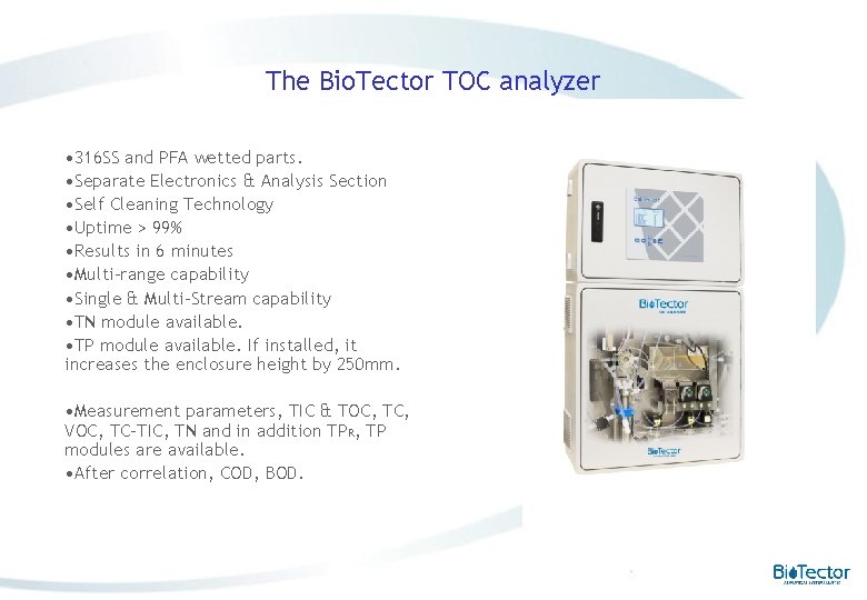
The Bio. Tector TOC analyzer • 316 SS and PFA wetted parts. • Separate Electronics & Analysis Section • Self Cleaning Technology • Uptime > 99% • Results in 6 minutes • Multi-range capability • Single & Multi-Stream capability • TN module available. • TP module available. If installed, it increases the enclosure height by 250 mm. • Measurement parameters, TIC & TOC, TC, VOC, TC-TIC, TN and in addition TPR, TP modules are available. • After correlation, COD, BOD.
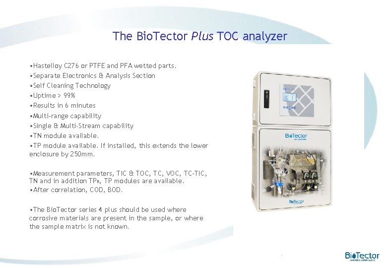
The Bio. Tector Plus TOC analyzer • Hastelloy C 276 or PTFE and PFA wetted parts. • Separate Electronics & Analysis Section • Self Cleaning Technology • Uptime > 99% • Results in 6 minutes • Multi-range capability • Single & Multi-Stream capability • TN module available. • TP module available. If installed, this extends the lower enclosure by 250 mm. • Measurement parameters, TIC & TOC, TC, VOC, TC-TIC, TN and in addition TPR, TP modules are available. • After correlation, COD, BOD. • The Bio. Tector series 4 plus should be used where corrosive materials are present in the sample, or where the sample matrix is not known.
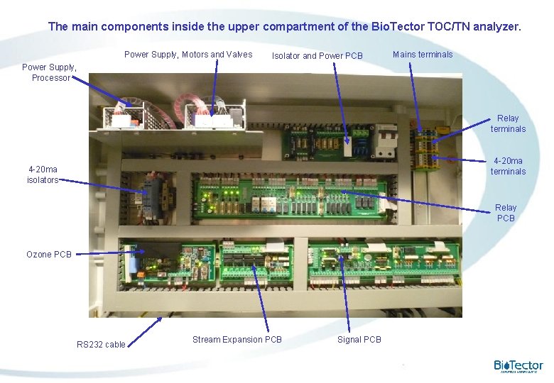
The main components inside the upper compartment of the Bio. Tector TOC/TN analyzer. Power Supply, Motors and Valves Isolator and Power PCB Mains terminals Power Supply, Processor Relay terminals 4 -20 ma isolators Relay PCB Ozone PCB RS 232 cable Stream Expansion PCB Signal PCB
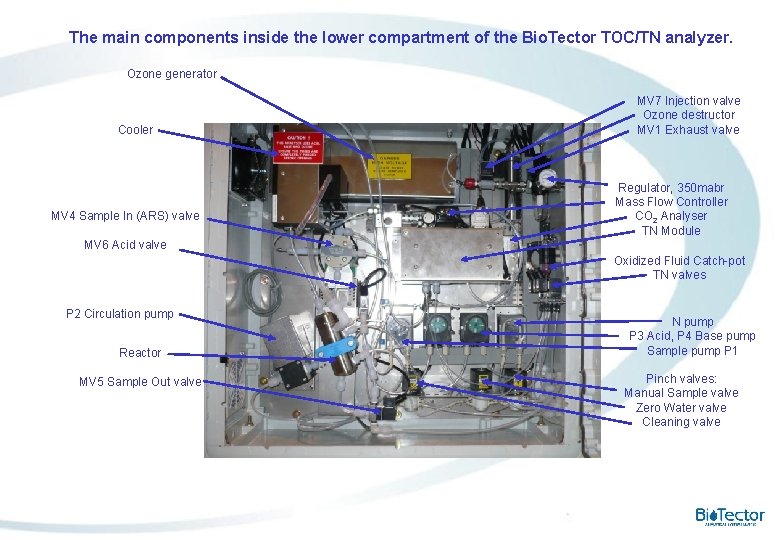
The main components inside the lower compartment of the Bio. Tector TOC/TN analyzer. Ozone generator Cooler MV 4 Sample In (ARS) valve MV 7 Injection valve Ozone destructor MV 1 Exhaust valve Regulator, 350 mabr Mass Flow Controller CO 2 Analyser TN Module MV 6 Acid valve Oxidized Fluid Catch-pot TN valves P 2 Circulation pump Reactor MV 5 Sample Out valve N pump P 3 Acid, P 4 Base pump Sample pump P 1 Pinch valves: Manual Sample valve Zero Water valve Cleaning valve

Problems associated with On-Line TOC measurement. Existing TOC Technologies and Limitations.
PROBLEMS ASSOCIATED WITH ONLINE TOC MEASUREMENT: Manufacturers have struggled to build reliable TOC analyzers. Existing Technologies not flexible enough to overcome problems and limitations such as: v Contamination and drift resulting in high maintenance. v Requirement for filtration and micro-sampling systems resulting in unrepresentative TOC and system failure. v Analyzer failure due to salts or calcium in the sample. v Difficulty in analyzing volatile organics.
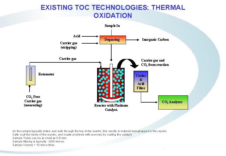
EXISTING TOC TECHNOLOGIES: THERMAL OXIDATION Sample In Acid Carrier gas (stripping) Degassing Carrier gas and CO 2 from reaction Rotometer CO 2 Free Carrier gas (measuring) Inorganic Carbon Cooler & Acid Filter Reactor with Platinum Catalyst. CO 2 Analyzer As the sample typically enters and exits through the top of the reactor, this results in material being trapped in the reactor. Salts coat the inside of the reactor, and create problems with recovery by coating the catalyst. Sample Tubes can be as small as 0. 5 mm. Sample filtering is typically <200 micron. Sample Volume < 10 micro-litres.
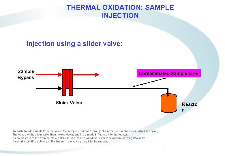
THERMAL OXIDATION: SAMPLE INJECTION Injection using a slider valve: Sample Bypass Contaminated Sample Line Slider Valve To flush the old sample from the valve, the sample is pumped through the upper port of the slider valve (as shown). The centre of the slider valve then moves down, and the sample is flushed into the reactor. As the valve is made from ceramic, salts can crystallize around the slider mechanism, causing it to seize. It can also be difficult to clean the line from the valve going into the reactor. Reacto r
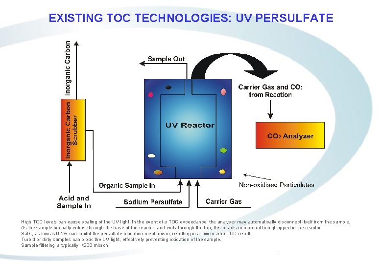
EXISTING TOC TECHNOLOGIES: UV PERSULFATE High TOC levels can cause scaling of the UV light. In the event of a TOC exceedance, the analyser may automatically disconnect itself from the sample. As the sample typically enters through the base of the reactor, and exits through the top, this results in material beingtrapped in the reactor. Salts, as low as 0. 5% can inhibit the persulfate oxidation mechanism, resulting in a low or zero TOC result. Turbid or dirty samples can block the UV light, effectively preventing oxidation of the sample. Sample filtering is typically <200 micron.
The patented Two Stage Advanced Oxidation process.
Bio. Tector Series 4 Compliance with European Norm EN 1484 Section 4: Principle states: “Oxidation of organic carbon in water to carbon dioxide by combustion, by the addition of an appropriate oxidant, by UV radiation or any other high energy radiation. ” “The final determination of CO 2 is carried out by a number of different procedures, for example infrared spectrometry, titration, thermal conductivity, conductometry, coulometry, CO 2 sensitive sensors and flame ionization detection. ”
Bio. Tector Series 4 Compliance with US EPA 415. 1 Section 2. 0: Summary of Method states: “Organic carbon in a sample is converted to carbon dioxide (CO 2) by catalytic combustion or wet chemical oxidation. The CO 2 formed can be measured directly by an infrared detector or converted to methane (CH 4) and measured by a flame ionization detector. The amount of CO 2 or CH 4 is directly proportional to the concentration of carbonaceous material in the sample. ”
Bio. Tector Series 4 Compliance with ASTM D 5173 -97 Standard Test Method for: “On-Line Monitoring of Carbon Compounds in Water by Chemical Oxidation, by UV Light Oxidation, by Both, or by High Temperature Combustion Followed by Gas Phase NDIR or by Electrolytic Conductivity (of the released CO 2 gas). ”
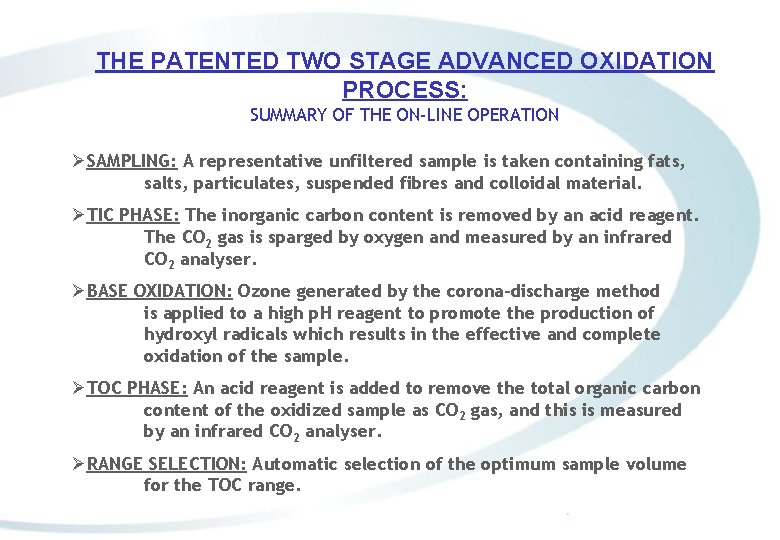
THE PATENTED TWO STAGE ADVANCED OXIDATION PROCESS: SUMMARY OF THE ON-LINE OPERATION ØSAMPLING: A representative unfiltered sample is taken containing fats, salts, particulates, suspended fibres and colloidal material. ØTIC PHASE: The inorganic carbon content is removed by an acid reagent. The CO 2 gas is sparged by oxygen and measured by an infrared CO 2 analyser. ØBASE OXIDATION: Ozone generated by the corona-discharge method is applied to a high p. H reagent to promote the production of hydroxyl radicals which results in the effective and complete oxidation of the sample. ØTOC PHASE: An acid reagent is added to remove the total organic carbon content of the oxidized sample as CO 2 gas, and this is measured by an infrared CO 2 analyser. ØRANGE SELECTION: Automatic selection of the optimum sample volume for the TOC range.
Operation of the COD TOC TN analyzer: TOC or Oxidation (OXP) phase.
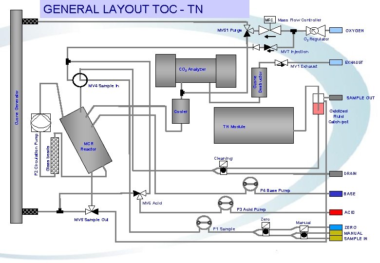
GENERAL LAYOUT TOC - TN MFC Mass Flow Controller MV 51 Purge OXYGEN O 2 Regulator MV 7 Injection MV 1 Exhaust Ozone Destructor CO 2 Analyzer MV 4 Sample In Ozone Generator EXHAUST SAMPLE OUT Oxidized Fluid Catch-pot Cooler Glass beads P 2 Circulation Pump TN Module MCR Reactor Cleaning DRAIN P 4 Base Pump BASE MV 6 Acid P 3 Acid Pump Zero MV 5 Sample Out P 1 Sample ACID Manual ZERO MANUAL SAMPLE IN
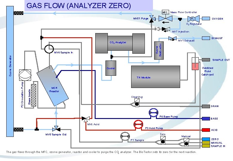
GAS FLOW (ANALYZER ZERO) MFC Mass Flow Controller MV 51 Purge OXYGEN O 2 Regulator MV 7 Injection MV 1 Exhaust Ozone Destructor CO 2 Analyzer MV 4 Sample In Ozone Generator EXHAUST SAMPLE OUT Oxidized Fluid Catch-pot Cooler Glass beads P 2 Circulation Pump TN Module MCR Reactor Cleaning DRAIN P 4 Base Pump BASE MV 6 Acid P 3 Acid Pump Zero MV 5 Sample Out ACID Manual P 1 Sample The gas flows through the MFC, ozone generator, reactor and cooler to purge the CO 2 analyzer. The Bio. Tector sets its zero for the next reaction. ZERO MANUAL SAMPLE IN
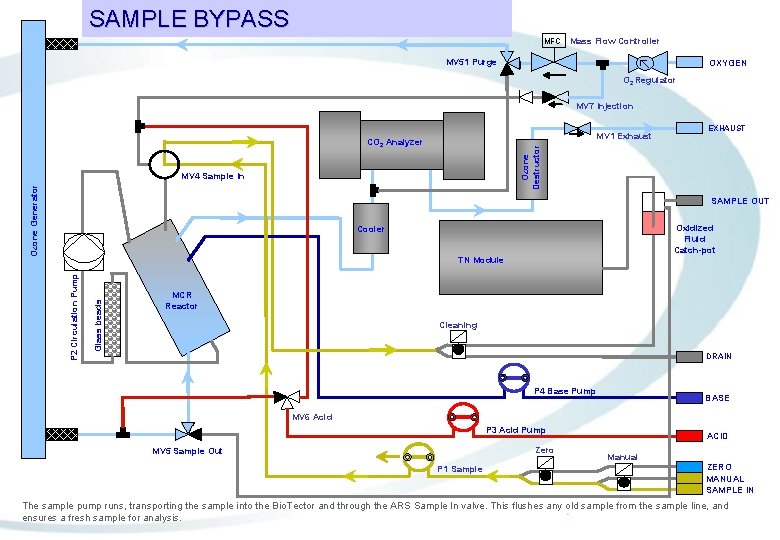
SAMPLE BYPASS MFC Mass Flow Controller MV 51 Purge OXYGEN O 2 Regulator MV 7 Injection MV 1 Exhaust Ozone Destructor CO 2 Analyzer MV 4 Sample In Ozone Generator EXHAUST SAMPLE OUT Oxidized Fluid Catch-pot Cooler Glass beads P 2 Circulation Pump TN Module MCR Reactor Cleaning DRAIN P 4 Base Pump BASE MV 6 Acid P 3 Acid Pump Zero MV 5 Sample Out P 1 Sample ACID Manual ZERO MANUAL SAMPLE IN The sample pump runs, transporting the sample into the Bio. Tector and through the ARS Sample In valve. This flushes any old sample from the sample line, and ensures a fresh sample for analysis.
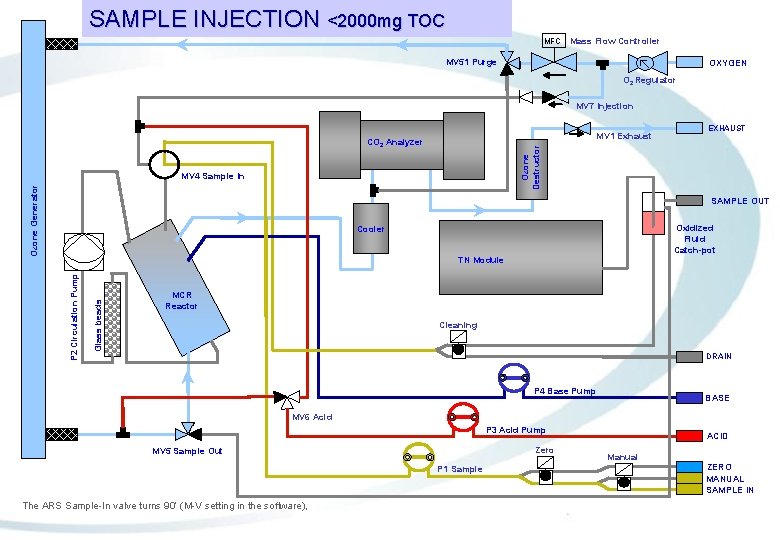
SAMPLE INJECTION <2000 mg TOC MFC Mass Flow Controller MV 51 Purge OXYGEN O 2 Regulator MV 7 Injection MV 1 Exhaust Ozone Destructor CO 2 Analyzer MV 4 Sample In Ozone Generator EXHAUST SAMPLE OUT Oxidized Fluid Catch-pot Cooler Glass beads P 2 Circulation Pump TN Module MCR Reactor Cleaning DRAIN P 4 Base Pump BASE MV 6 Acid P 3 Acid Pump Zero MV 5 Sample Out P 1 Sample The ARS Sample-In valve turns 90’ (M-V setting in the software), ACID Manual ZERO MANUAL SAMPLE IN
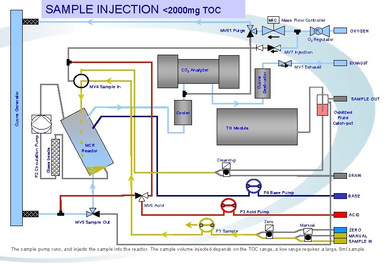
SAMPLE INJECTION <2000 mg TOC MFC Mass Flow Controller MV 51 Purge OXYGEN O 2 Regulator MV 7 Injection MV 1 Exhaust Ozone Destructor CO 2 Analyzer MV 4 Sample In Ozone Generator EXHAUST SAMPLE OUT Oxidized Fluid Catch-pot Cooler Glass beads P 2 Circulation Pump TN Module MCR Reactor Cleaning DRAIN P 4 Base Pump BASE MV 6 Acid P 3 Acid Pump Zero MV 5 Sample Out P 1 Sample ACID Manual ZERO MANUAL SAMPLE IN The sample pump runs, and injects the sample into the reactor. The sample volume injected depends on the TOC range, a low range requires a large, 8 ml sample.
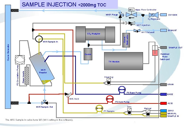
SAMPLE INJECTION <2000 mg TOC MFC Mass Flow Controller MV 51 Purge OXYGEN O 2 Regulator MV 7 Injection MV 1 Exhaust Ozone Destructor CO 2 Analyzer MV 4 Sample In Ozone Generator EXHAUST SAMPLE OUT Oxidized Fluid Catch-pot Cooler Glass beads P 2 Circulation Pump TN Module MCR Reactor Cleaning DRAIN P 4 Base Pump BASE MV 6 Acid P 3 Acid Pump Zero MV 5 Sample Out P 1 Sample The ARS Sample-In valve turns 90’ (M-V setting in the software), ACID Manual ZERO MANUAL SAMPLE IN
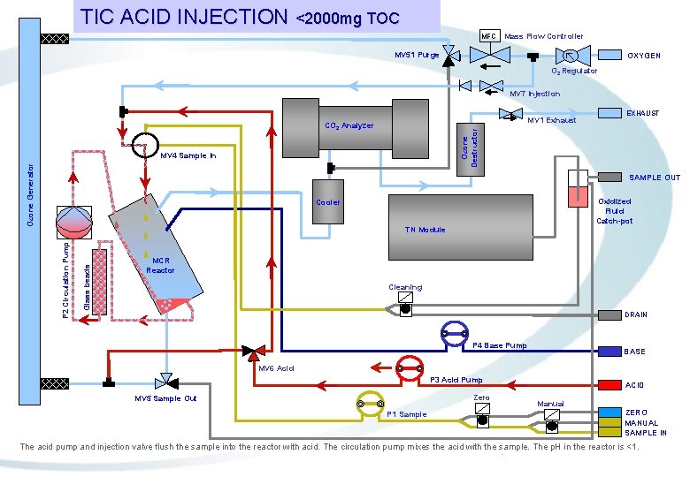
TIC ACID INJECTION <2000 mg TOC MFC Mass Flow Controller MV 51 Purge OXYGEN O 2 Regulator MV 7 Injection MV 1 Exhaust Ozone Destructor CO 2 Analyzer MV 4 Sample In Ozone Generator EXHAUST SAMPLE OUT Oxidized Fluid Catch-pot Cooler Glass beads P 2 Circulation Pump TN Module MCR Reactor Cleaning DRAIN P 4 Base Pump BASE MV 6 Acid P 3 Acid Pump Zero MV 5 Sample Out P 1 Sample ACID Manual ZERO MANUAL SAMPLE IN The acid pump and injection valve flush the sample into the reactor with acid. The circulation pump mixes the acid with the sample. The p. H in the reactor is <1.
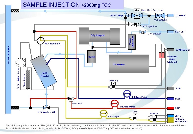
SAMPLE INJECTION >2000 mg TOC MFC Mass Flow Controller MV 51 Purge OXYGEN O 2 Regulator MV 7 Injection MV 1 Exhaust Ozone Destructor CO 2 Analyzer MV 4 Sample In Ozone Generator EXHAUST SAMPLE OUT Oxidized Fluid Catch-pot Cooler Glass beads P 2 Circulation Pump TN Module MCR Reactor Cleaning DRAIN P 4 Base Pump BASE MV 6 Acid P 3 Acid Pump Zero MV 5 Sample Out P 1 Sample ACID Manual ZERO MANUAL SAMPLE IN The ARS Sample-In valve turns 180’ (M-F 180 setting in the software), and the sample injected by the TIC acid is the sample contained within the valve when it turns. Several fixed volumes are available, from 0. 12 ml (10, 000 mg TOC) to 0. 02 ml (up to 100, 000 mg TOC with extended oxidation).
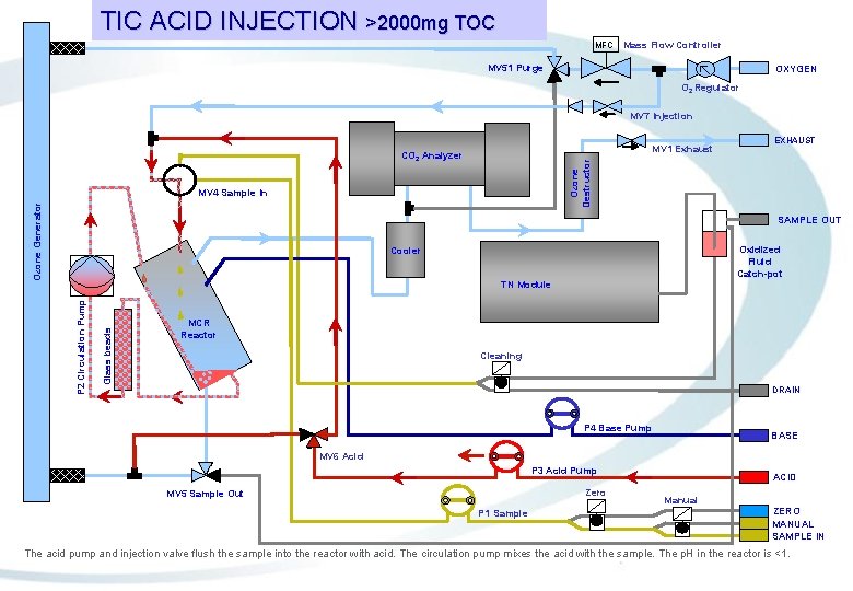
TIC ACID INJECTION >2000 mg TOC MFC Mass Flow Controller MV 51 Purge OXYGEN O 2 Regulator MV 7 Injection MV 1 Exhaust Ozone Destructor CO 2 Analyzer MV 4 Sample In Ozone Generator EXHAUST SAMPLE OUT Oxidized Fluid Catch-pot Cooler Glass beads P 2 Circulation Pump TN Module MCR Reactor Cleaning DRAIN P 4 Base Pump BASE MV 6 Acid P 3 Acid Pump Zero MV 5 Sample Out P 1 Sample ACID Manual ZERO MANUAL SAMPLE IN The acid pump and injection valve flush the sample into the reactor with acid. The circulation pump mixes the acid with the sample. The p. H in the reactor is <1.
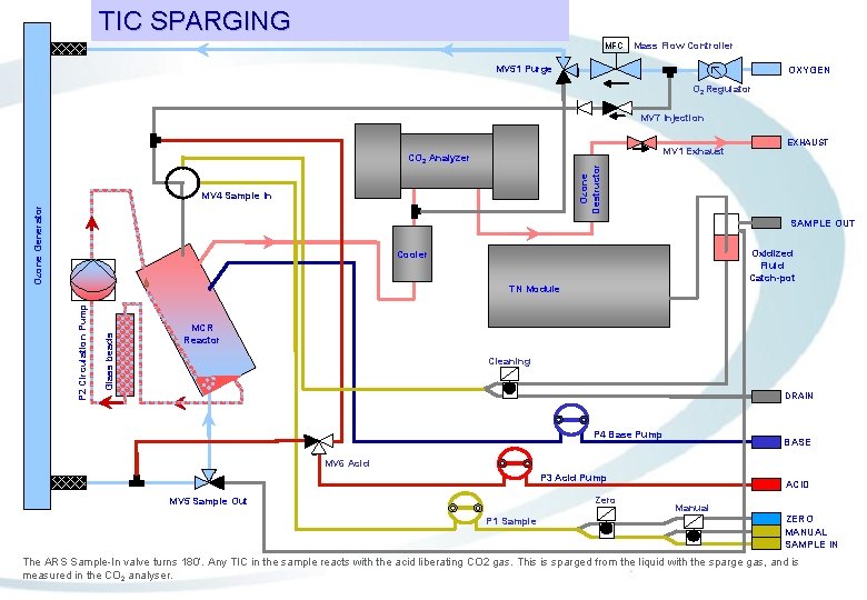
TIC SPARGING MFC Mass Flow Controller MV 51 Purge OXYGEN O 2 Regulator MV 7 Injection MV 1 Exhaust Ozone Destructor CO 2 Analyzer MV 4 Sample In Ozone Generator EXHAUST SAMPLE OUT Oxidized Fluid Catch-pot Cooler Glass beads P 2 Circulation Pump TN Module MCR Reactor Cleaning DRAIN P 4 Base Pump BASE MV 6 Acid P 3 Acid Pump Zero MV 5 Sample Out P 1 Sample ACID Manual ZERO MANUAL SAMPLE IN The ARS Sample-In valve turns 180’. Any TIC in the sample reacts with the acid liberating CO 2 gas. This is sparged from the liquid with the sparge gas, and is measured in the CO 2 analyser.
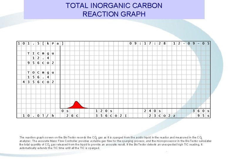
TOTAL INORGANIC CARBON REACTION GRAPH The reaction graph screen on the Bio. Tector records the CO 2 gas as it is sparged from the acidic liquid in the reactor and measured in the CO 2 analyzer. The accurate Mass Flow Controller provides a stable gas flow for the sparging process, and the microprocessor in the Bio. Tector calculates the total quantity of CO 2 gas released from the liquid to provide an accurate result. If the Bio. Tector detects an unexpected high TIC reading, it automatically extends the TIC time until all the TIC is sparged.
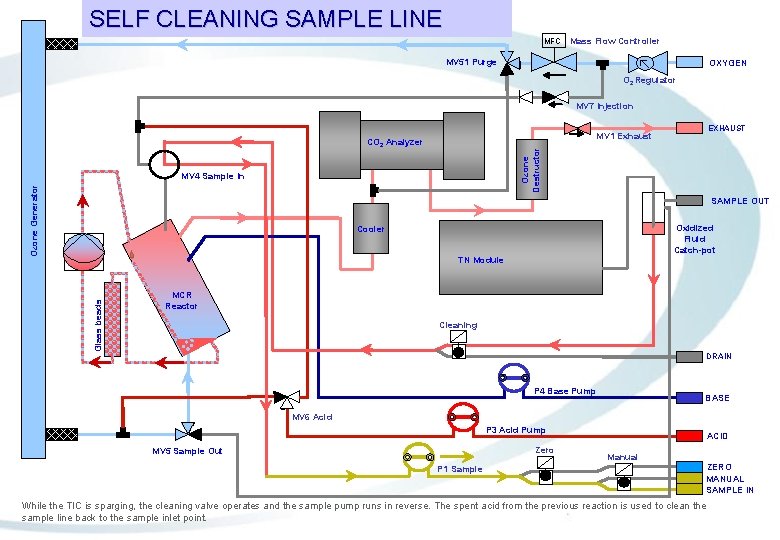
SELF CLEANING SAMPLE LINE MFC Mass Flow Controller MV 51 Purge OXYGEN O 2 Regulator MV 7 Injection Ozone Destructor CO 2 Analyzer MV 4 Sample In Ozone Generator EXHAUST MV 1 Exhaust SAMPLE OUT Oxidized Fluid Catch-pot Cooler Glass beads TN Module MCR Reactor Cleaning DRAIN P 4 Base Pump BASE MV 6 Acid P 3 Acid Pump Zero MV 5 Sample Out P 1 Sample ACID Manual ZERO MANUAL SAMPLE IN While the TIC is sparging, the cleaning valve operates and the sample pump runs in reverse. The spent acid from the previous reaction is used to clean the sample line back to the sample inlet point.
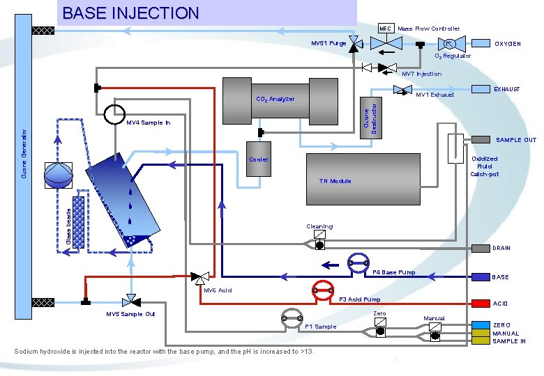
BASE INJECTION MFC Mass Flow Controller MV 51 Purge OXYGEN O 2 Regulator MV 7 Injection MV 1 Exhaust Ozone Destructor CO 2 Analyzer MV 4 Sample In Ozone Generator EXHAUST SAMPLE OUT Oxidized Fluid Catch-pot Cooler Glass beads TN Module Cleaning DRAIN P 4 Base Pump BASE MV 6 Acid P 3 Acid Pump Zero MV 5 Sample Out P 1 Sample Sodium hydroxide is injected into the reactor with the base pump, and the p. H is increased to >13. ACID Manual ZERO MANUAL SAMPLE IN
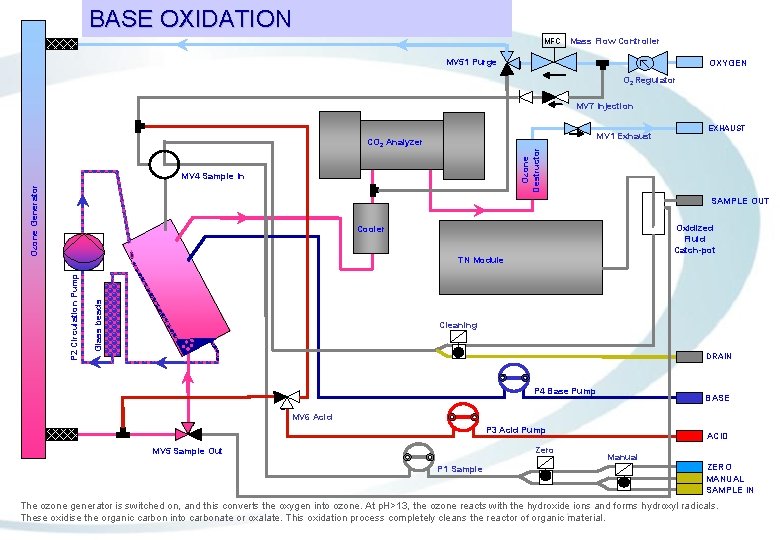
BASE OXIDATION MFC Mass Flow Controller MV 51 Purge OXYGEN O 2 Regulator MV 7 Injection MV 1 Exhaust Ozone Destructor CO 2 Analyzer MV 4 Sample In Ozone Generator EXHAUST SAMPLE OUT Oxidized Fluid Catch-pot Cooler Glass beads P 2 Circulation Pump TN Module Cleaning DRAIN P 4 Base Pump BASE MV 6 Acid P 3 Acid Pump Zero MV 5 Sample Out P 1 Sample ACID Manual ZERO MANUAL SAMPLE IN The ozone generator is switched on, and this converts the oxygen into ozone. At p. H>13, the ozone reacts with the hydroxide ions and forms hydroxyl radicals. These oxidise the organic carbon into carbonate or oxalate. This oxidation process completely cleans the reactor of organic material.
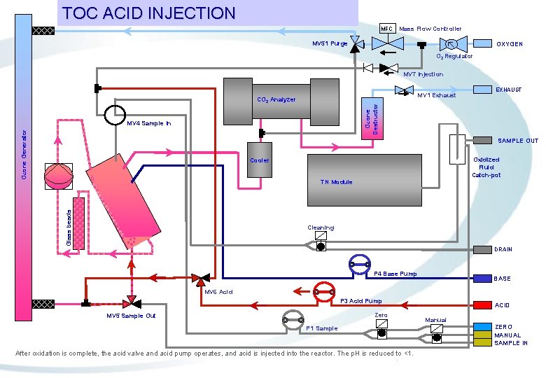
TOC ACID INJECTION MFC Mass Flow Controller MV 51 Purge OXYGEN O 2 Regulator MV 7 Injection MV 1 Exhaust Ozone Destructor CO 2 Analyzer MV 4 Sample In Ozone Generator EXHAUST SAMPLE OUT Oxidized Fluid Catch-pot Cooler Glass beads TN Module Cleaning DRAIN P 4 Base Pump BASE MV 6 Acid P 3 Acid Pump Zero MV 5 Sample Out P 1 Sample After oxidation is complete, the acid valve and acid pump operates, and acid is injected into the reactor. The p. H is reduced to <1. ACID Manual ZERO MANUAL SAMPLE IN
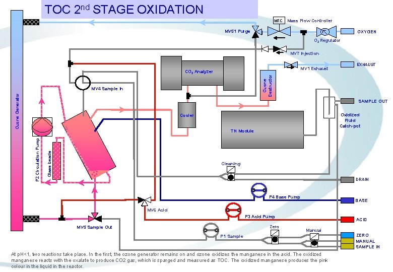
TOC 2 nd STAGE OXIDATION MFC Mass Flow Controller MV 51 Purge OXYGEN O 2 Regulator MV 7 Injection MV 1 Exhaust Ozone Destructor CO 2 Analyzer MV 4 Sample In Ozone Generator EXHAUST SAMPLE OUT Oxidized Fluid Catch-pot Cooler Glass beads P 2 Circulation Pump TN Module Cleaning DRAIN P 4 Base Pump BASE MV 6 Acid P 3 Acid Pump Zero MV 5 Sample Out ACID Manual P 1 Sample At p. H<1, two reactions take place. In the first, the ozone generator remains on and ozone oxidizes the manganese in the acid. The oxidized manganese reacts with the oxalate to produce CO 2 gas, which is sparged and measured as TOC. The oxidized manganese produces the pink colour in the liquid in the reactor. ZERO MANUAL SAMPLE IN
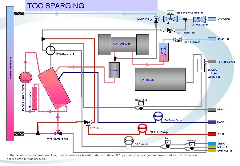
TOC SPARGING MFC Mass Flow Controller MV 51 Purge OXYGEN O 2 Regulator MV 7 Injection MV 1 Exhaust Ozone Destructor CO 2 Analyzer MV 4 Sample In Ozone Generator EXHAUST SAMPLE OUT Oxidized Fluid Catch-pot Cooler Glass beads P 2 Circulation Pump TN Module Cleaning DRAIN P 4 Base Pump BASE MV 6 Acid P 3 Acid Pump Zero MV 5 Sample Out ACID Manual P 1 Sample In the second simultaneous reaction, the acid reacts with carbonate to produce CO 2 gas, which is sparged and measured as TOC. Ozone is not required for this process. ZERO MANUAL SAMPLE IN
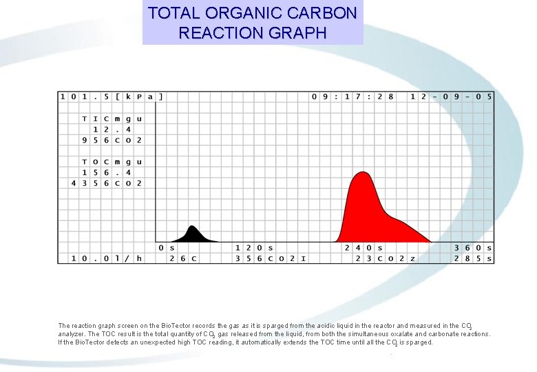
TOTAL ORGANIC CARBON REACTION GRAPH The reaction graph screen on the Bio. Tector records the gas as it is sparged from the acidic liquid in the reactor and measured in the CO 2 analyzer. The TOC result is the total quantity of CO 2 gas released from the liquid, from both the simultaneous oxalate and carbonate reactions. If the Bio. Tector detects an unexpected high TOC reading, it automatically extends the TOC time until all the CO 2 is sparged.
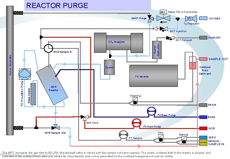
REACTOR PURGE MFC Mass Flow Controller MV 51 Purge OXYGEN O 2 Regulator MV 7 Injection MV 1 Exhaust Ozone Destructor CO 2 Analyzer MV 4 Sample In Ozone Generator EXHAUST SAMPLE OUT Oxidized Fluid Catch-pot Cooler Glass beads P 2 Circulation Pump TN Module MCR Reactor Cleaning DRAIN P 4 Base Pump BASE MV 6 Acid P 3 Acid Pump Zero MV 5 Sample Out P 1 Sample ACID Manual ZERO MANUAL SAMPLE IN The MFC increases the gas flow to 80 LPH, the exhaust valve is closed and the sample out valve opened. The acidic, oxidized fluid in the reactor is purged, and collected in the oxidized fluid catch-pot, where its characteristic pink colour generated by the oxidized manganese should be visible.
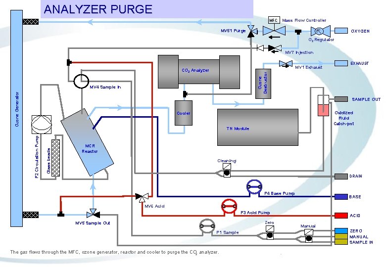
ANALYZER PURGE MFC Mass Flow Controller MV 51 Purge OXYGEN O 2 Regulator MV 7 Injection MV 1 Exhaust Ozone Destructor CO 2 Analyzer MV 4 Sample In Ozone Generator EXHAUST SAMPLE OUT Oxidized Fluid Catch-pot Cooler Glass beads P 2 Circulation Pump TN Module MCR Reactor Cleaning DRAIN P 4 Base Pump BASE MV 6 Acid P 3 Acid Pump Zero MV 5 Sample Out P 1 Sample The gas flows through the MFC, ozone generator, reactor and cooler to purge the CO 2 analyzer. ACID Manual ZERO MANUAL SAMPLE IN

Self Cleaning Technology and Intelligent Diagnostics.
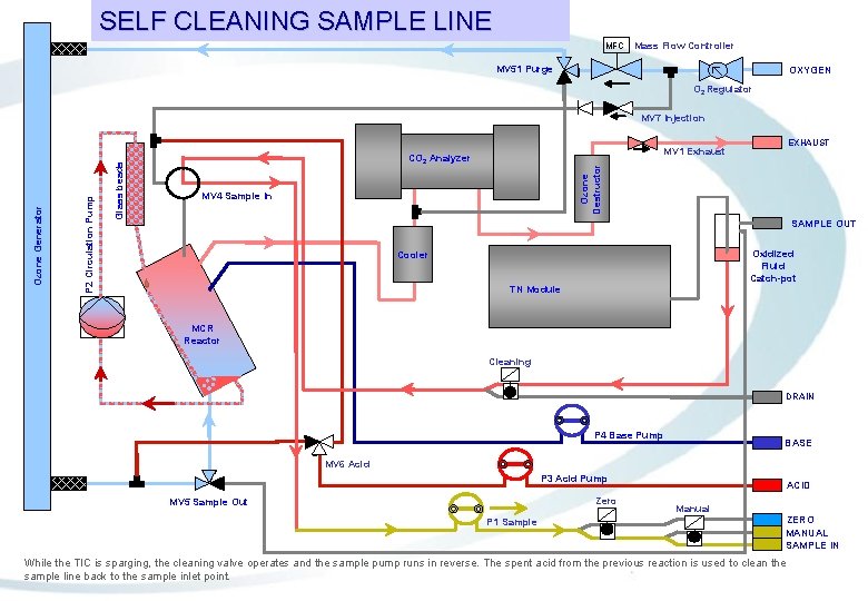
SELF CLEANING SAMPLE LINE MFC Mass Flow Controller MV 51 Purge OXYGEN O 2 Regulator EXHAUST MV 1 Exhaust CO 2 Analyzer Ozone Destructor Glass beads P 2 Circulation Pump Ozone Generator MV 7 Injection MV 4 Sample In SAMPLE OUT Oxidized Fluid Catch-pot Cooler TN Module MCR Reactor Cleaning DRAIN P 4 Base Pump BASE MV 6 Acid P 3 Acid Pump Zero MV 5 Sample Out P 1 Sample ACID Manual ZERO MANUAL SAMPLE IN While the TIC is sparging, the cleaning valve operates and the sample pump runs in reverse. The spent acid from the previous reaction is used to clean the sample line back to the sample inlet point.
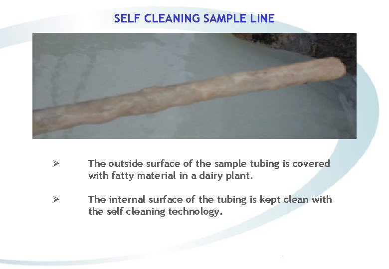
SELF CLEANING SAMPLE LINE Ø The outside surface of the sample tubing is covered with fatty material in a dairy plant. Ø The internal surface of the tubing is kept clean with the self cleaning technology.
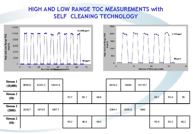
HIGH AND LOW RANGE TOC MEASUREMENTS with SELF CLEANING TECHNOLOGY Stream 1 (10, 000) 9656. 9 10301. 3 10041. 8 Stream 2 (50) Stream 1 (2000) Stream 2 (50) 9819. 3 53. 7 2039. 7 1974. 5 50. 1 2064. 1 49. 8 10116. 7 49. 6 1957. 7 50. 2 10064 49. 0 2000. 9 59. 1 50. 4 50. 3 49. 2 1998
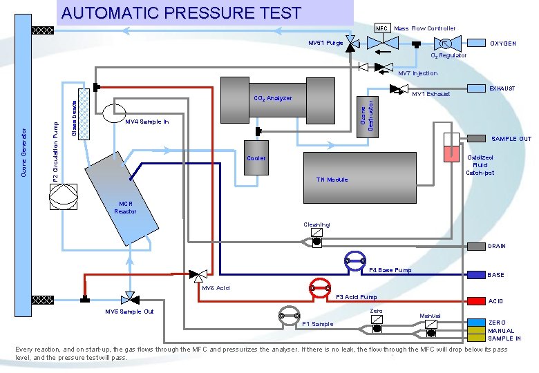
AUTOMATIC PRESSURE TEST MFC Mass Flow Controller MV 51 Purge OXYGEN O 2 Regulator MV 1 Exhaust CO 2 Analyzer EXHAUST Ozone Destructor Glass beads P 2 Circulation Pump Ozone Generator MV 7 Injection MV 4 Sample In SAMPLE OUT Oxidized Fluid Catch-pot Cooler TN Module MCR Reactor Cleaning DRAIN P 4 Base Pump BASE MV 6 Acid P 3 Acid Pump Zero MV 5 Sample Out P 1 Sample ACID Manual ZERO MANUAL SAMPLE IN Every reaction, and on start-up, the gas flows through the MFC and pressurizes the analyser. If there is no leak, the flow through the MFC will drop below its pass level, and the pressure test will pass.
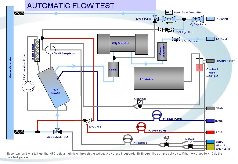
AUTOMATIC FLOW TEST MFC Mass Flow Controller MV 51 Purge OXYGEN O 2 Regulator MV 1 Exhaust CO 2 Analyzer EXHAUST Ozone Destructor Glass beads P 2 Circulation Pump Ozone Generator MV 7 Injection MV 4 Sample In SAMPLE OUT Oxidized Fluid Catch-pot Cooler TN Module MCR Reactor Cleaning DRAIN P 4 Base Pump BASE MV 6 Acid P 3 Acid Pump Zero MV 5 Sample Out P 1 Sample ACID Manual ZERO MANUAL SAMPLE IN Every day, and on start-up, the MFC sets a high flow through the exhaust valve and independently through the sample out valve. If the flow drops by <10%, the flow test passes.
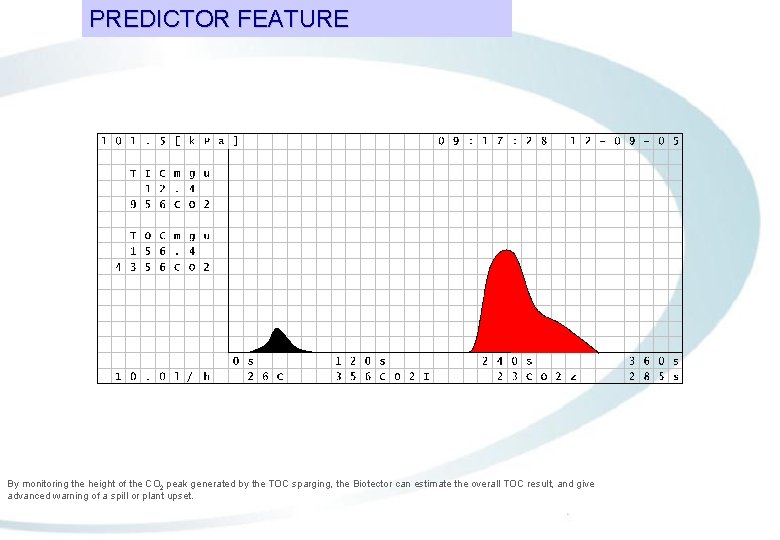
PREDICTOR FEATURE By monitoring the height of the CO 2 peak generated by the TOC sparging, the Biotector can estimate the overall TOC result, and give advanced warning of a spill or plant upset.
Operation of the COD TOC TN analyzer: TN or Liquid Phase Analysis (LQP) phase.
Operation of the TN module. Operation of the TN module, a brief summary: -When the Bio. Tector oxidises organic carbon it also oxidises nitrite, ammonia and bound nitrogen into nitrate, NO 3 -. -The TN module collects the Bio. Tectors TOC sample out fluid, and analyses it for the presence of NO 3 -. The TN result is available about 2 minutes after the TOC result. -After measurement, the TN module returns the sample out fluid to the Bio. Tectors cleaning cycle vessel so that it can be used for reverse wash cleaning. -The overall reaction time with the TN module is typically <9 minutes.
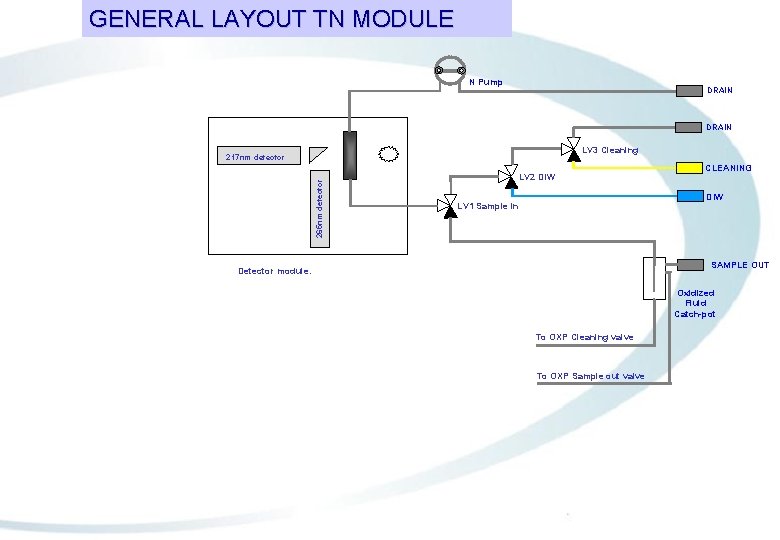
GENERAL LAYOUT TN MODULE N Pump DRAIN LV 3 Cleaning 265 nm detector 217 nm detector LV 2 DIW CLEANING DIW LV 1 Sample in SAMPLE OUT Detector module. Oxidized Fluid Catch-pot To OXP Cleaning valve To OXP Sample out valve
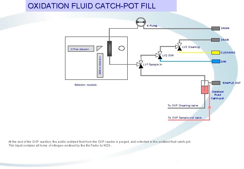
OXIDATION FLUID CATCH-POT FILL N Pump DRAIN LV 3 Cleaning 265 nm detector 217 nm detector LV 2 DIW CLEANING DIW LV 1 Sample in SAMPLE OUT Detector module. Oxidized Fluid Catch-pot To OXP Cleaning valve To OXP Sample out valve At the end of the OXP reaction, the acidic oxidized fluid from the OXP reactor is purged, and collected in the oxidized fluid catch-pot. This liquid contains all forms of nitrogen oxidised by the Bio. Tector to NO 3 -.
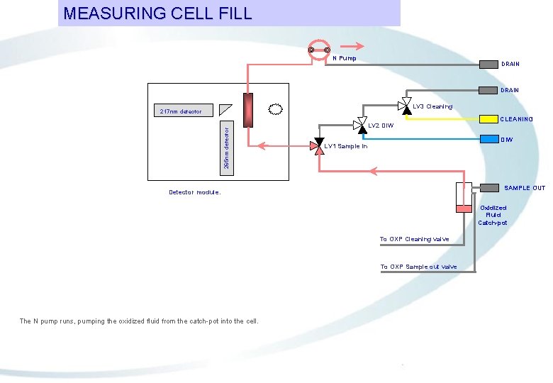
MEASURING CELL FILL N Pump DRAIN LV 3 Cleaning 265 nm detector 217 nm detector LV 2 DIW CLEANING DIW LV 1 Sample in SAMPLE OUT Detector module. Oxidized Fluid Catch-pot To OXP Cleaning valve To OXP Sample out valve The N pump runs, pumping the oxidized fluid from the catch-pot into the cell.
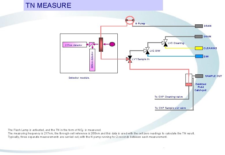
TN MEASURE N Pump DRAIN LV 3 Cleaning 265 nm detector 217 nm detector CLEANING LV 2 DIW LV 1 Sample in SAMPLE OUT Detector module. Oxidized Fluid Catch-pot To OXP Cleaning valve To OXP Sample out valve The Flash Lamp is activated, and the TN in the form of NO 3 - is measured. The measuring frequency is 217 nm, the through-cell reference is 265 nm and this data is used with the cell zero readings to calculate the TN result. Typically, three separate measurements are carried out, with the N pump running for 2 seconds between each measurement.
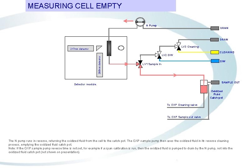
MEASURING CELL EMPTY N Pump DRAIN LV 3 Cleaning 265 nm detector 217 nm detector LV 2 DIW CLEANING DIW LV 1 Sample in SAMPLE OUT Detector module. Oxidized Fluid Catch-pot To OXP Cleaning valve To OXP Sample out valve The N pump runs in reverse, returning the oxidized fluid from the cell to the catch-pot. The OXP sample pump then uses the oxidized fluid in its reverse cleaning process, emptying the oxidized fluid catch pot. Note: If the OXP sample pump reverse time is not set, for example if a span calibration is run, then the oxidized fluid is pumped to drain by the N pump, not into the oxidized fluid catch pot (not shown on presentation).
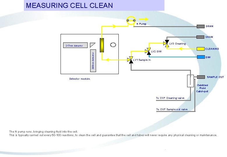
MEASURING CELL CLEAN N Pump DRAIN LV 3 Cleaning 265 nm detector 217 nm detector LV 2 DIW CLEANING DIW LV 1 Sample in SAMPLE OUT Detector module. Oxidized Fluid Catch-pot To OXP Cleaning valve To OXP Sample out valve The N pump runs, bringing cleaning fluid into the cell. This is typically carried out every 50 -100 reactions, to clean the cell and guarantee that the cell and tubes will never require any physical cleaning or maintenance.
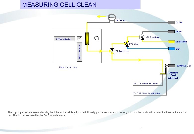
MEASURING CELL CLEAN N Pump DRAIN LV 3 Cleaning 265 nm detector 217 nm detector LV 2 DIW CLEANING DIW LV 1 Sample in SAMPLE OUT Detector module. Oxidized Fluid Catch-pot To OXP Cleaning valve To OXP Sample out valve The N pump runs in reverse, cleaning the tube to the catch-pot, and additionally puts a few drops of cleaning fluid into the catch-pot to clean the base of the catchpot. This is later removed by the OXP sample pump.
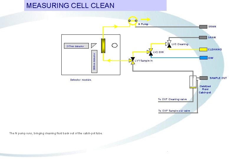
MEASURING CELL CLEAN N Pump DRAIN LV 3 Cleaning 265 nm detector 217 nm detector LV 2 DIW CLEANING DIW LV 1 Sample in SAMPLE OUT Detector module. Oxidized Fluid Catch-pot To OXP Cleaning valve To OXP Sample out valve The N pump runs, bringing cleaning fluid back out of the catch-pot tube.
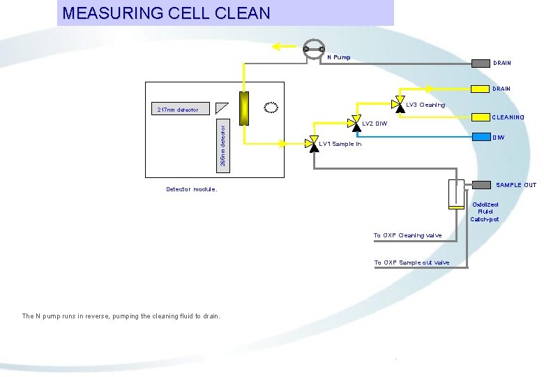
MEASURING CELL CLEAN N Pump DRAIN LV 3 Cleaning 265 nm detector 217 nm detector LV 2 DIW CLEANING DIW LV 1 Sample in SAMPLE OUT Detector module. Oxidized Fluid Catch-pot To OXP Cleaning valve To OXP Sample out valve The N pump runs in reverse, pumping the cleaning fluid to drain.
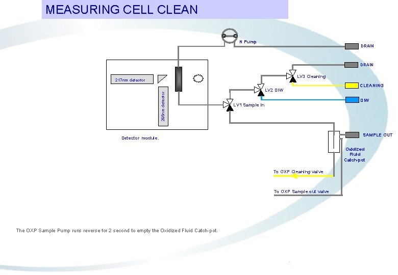
GENERAL MEASURING LAYOUT CELL CLEAN TN MODULE N Pump DRAIN LV 3 Cleaning 265 nm detector 217 nm detector LV 2 DIW CLEANING DIW LV 1 Sample in SAMPLE OUT Detector module. Oxidized Fluid Catch-pot To OXP Cleaning valve To OXP Sample out valve The OXP Sample Pump runs reverse for 2 second to empty the Oxidized Fluid Catch-pot.
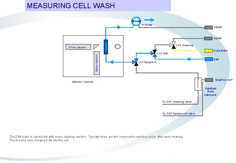
MEASURING CELL WASH N Pump DRAIN LV 3 Cleaning 265 nm detector 217 nm detector LV 2 DIW CLEANING DIW LV 1 Sample in SAMPLE OUT Detector module. Oxidized Fluid Catch-pot To OXP Cleaning valve To OXP Sample out valve The DIW wash is carried out after every cleaning reaction. Typically there are two consecutive washing cycles after each cleaning. The N pump runs, bringing DIW into the cell.
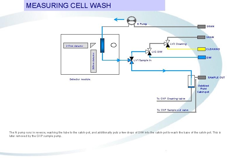
MEASURING CELL WASH N Pump DRAIN LV 3 Cleaning 265 nm detector 217 nm detector LV 2 DIW CLEANING DIW LV 1 Sample in SAMPLE OUT Detector module. Oxidized Fluid Catch-pot To OXP Cleaning valve To OXP Sample out valve The N pump runs in reverse, washing the tube to the catch-pot, and additionally puts a few drops of DIW into the catch-pot to wash the base of the catch-pot. This is later removed by the OXP sample pump.
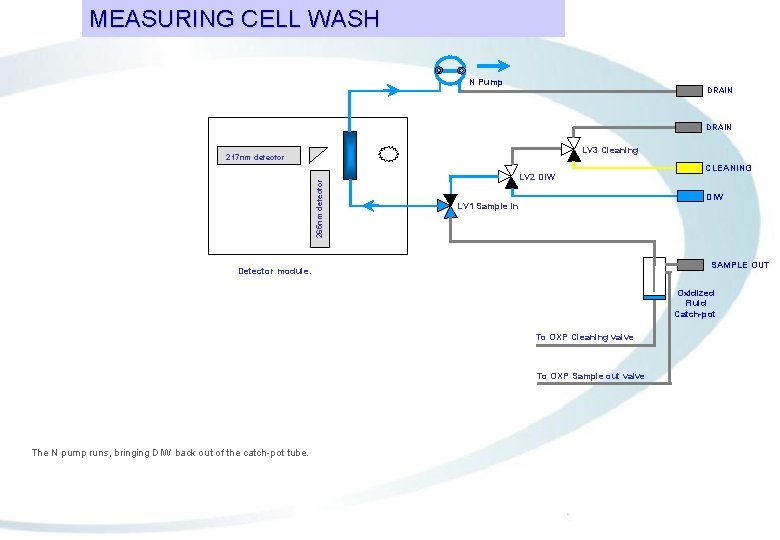
MEASURING CELL WASH N Pump DRAIN LV 3 Cleaning 265 nm detector 217 nm detector LV 2 DIW CLEANING DIW LV 1 Sample in SAMPLE OUT Detector module. Oxidized Fluid Catch-pot To OXP Cleaning valve To OXP Sample out valve The N pump runs, bringing DIW back out of the catch-pot tube.
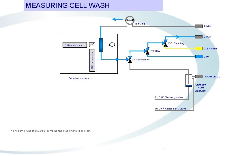
MEASURING CELL WASH N Pump DRAIN LV 3 Cleaning 265 nm detector 217 nm detector LV 2 DIW CLEANING DIW LV 1 Sample in SAMPLE OUT Detector module. Oxidized Fluid Catch-pot To OXP Cleaning valve To OXP Sample out valve The N pump runs in reverse, pumping the cleaning fluid to drain.
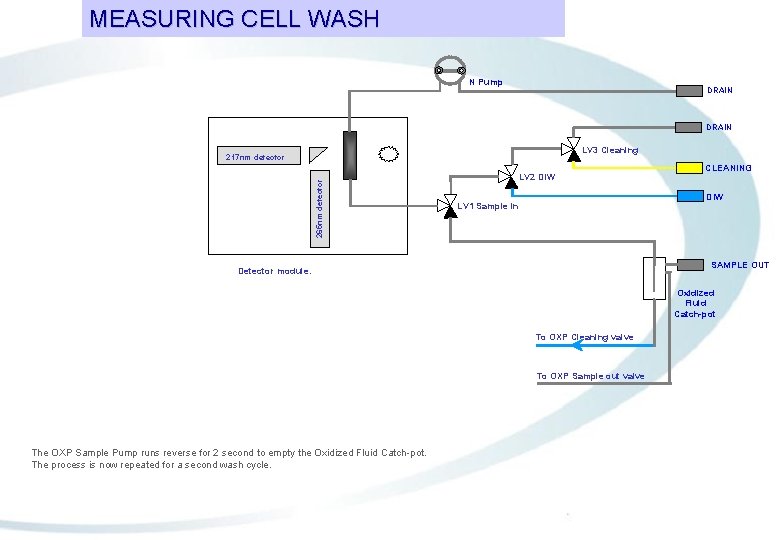
GENERAL MEASURING LAYOUT CELL WASH TN MODULE N Pump DRAIN LV 3 Cleaning 265 nm detector 217 nm detector LV 2 DIW CLEANING DIW LV 1 Sample in SAMPLE OUT Detector module. Oxidized Fluid Catch-pot To OXP Cleaning valve To OXP Sample out valve The OXP Sample Pump runs reverse for 2 second to empty the Oxidized Fluid Catch-pot. The process is now repeated for a second wash cycle.
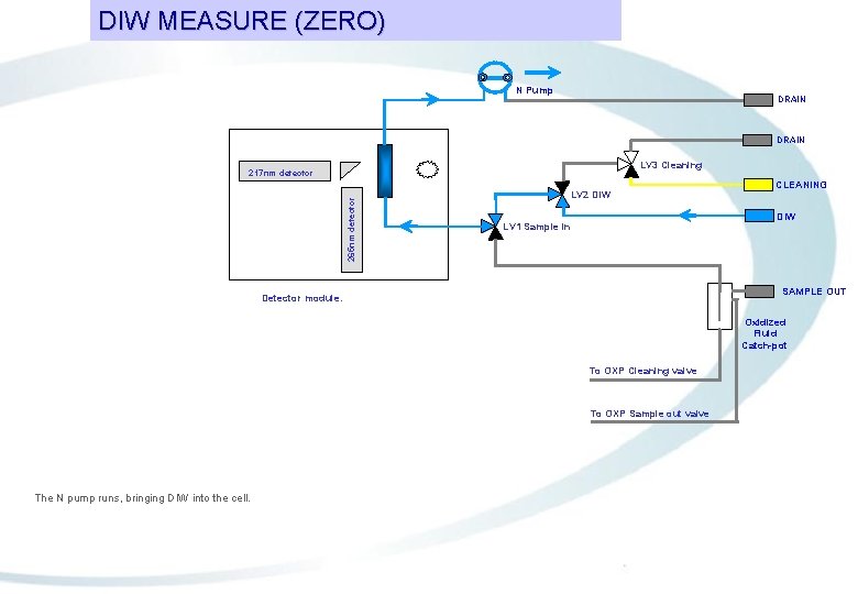
DIW MEASURE (ZERO) N Pump DRAIN LV 3 Cleaning 265 nm detector 217 nm detector LV 2 DIW CLEANING DIW LV 1 Sample in SAMPLE OUT Detector module. Oxidized Fluid Catch-pot To OXP Cleaning valve To OXP Sample out valve The N pump runs, bringing DIW into the cell.
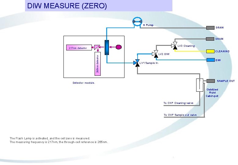
DIW MEASURE (ZERO) N Pump DRAIN LV 3 Cleaning 265 nm detector 217 nm detector LV 2 DIW CLEANING DIW LV 1 Sample in SAMPLE OUT Detector module. Oxidized Fluid Catch-pot To OXP Cleaning valve To OXP Sample out valve The Flash Lamp is activated, and the cell zero is measured. The measuring frequency is 217 nm, the through-cell reference is 265 nm.
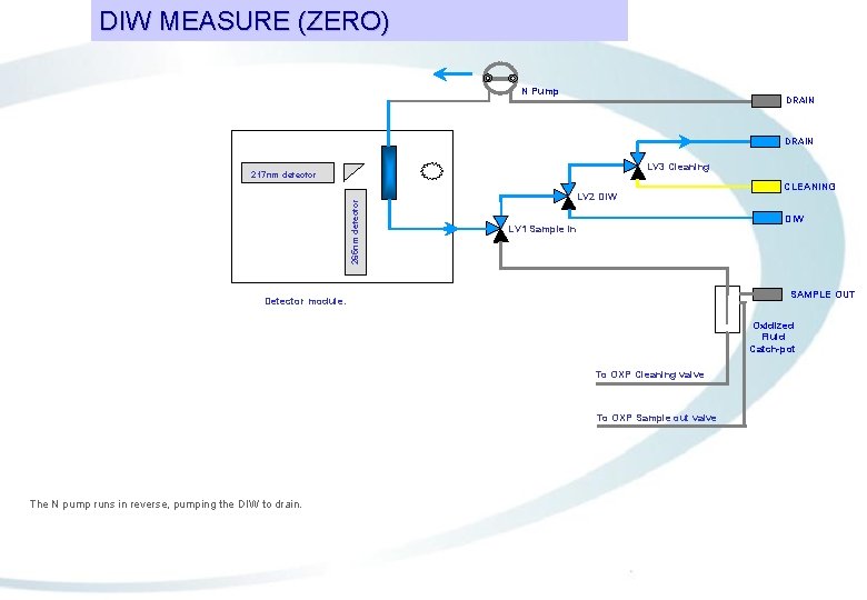
DIW MEASURE (ZERO) N Pump DRAIN LV 3 Cleaning 265 nm detector 217 nm detector LV 2 DIW CLEANING DIW LV 1 Sample in SAMPLE OUT Detector module. Oxidized Fluid Catch-pot To OXP Cleaning valve To OXP Sample out valve The N pump runs in reverse, pumping the DIW to drain.
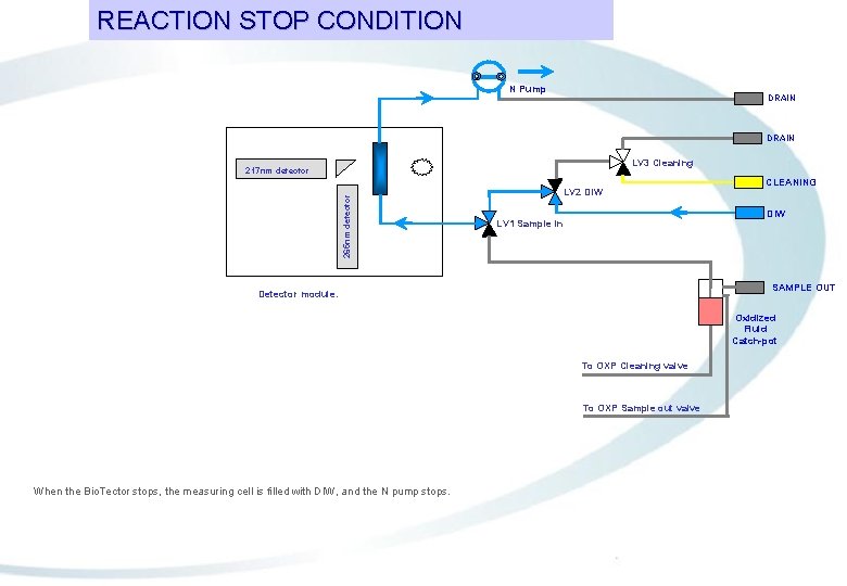
REACTION STOP CONDITION N Pump DRAIN LV 3 Cleaning 265 nm detector 217 nm detector LV 2 DIW CLEANING DIW LV 1 Sample in SAMPLE OUT Detector module. Oxidized Fluid Catch-pot To OXP Cleaning valve To OXP Sample out valve When the Bio. Tector stops, the measuring cell is filled with DIW, and the N pump stops.
Operation of the Bio. Tector COD TOC TN analyzer: COD calculation
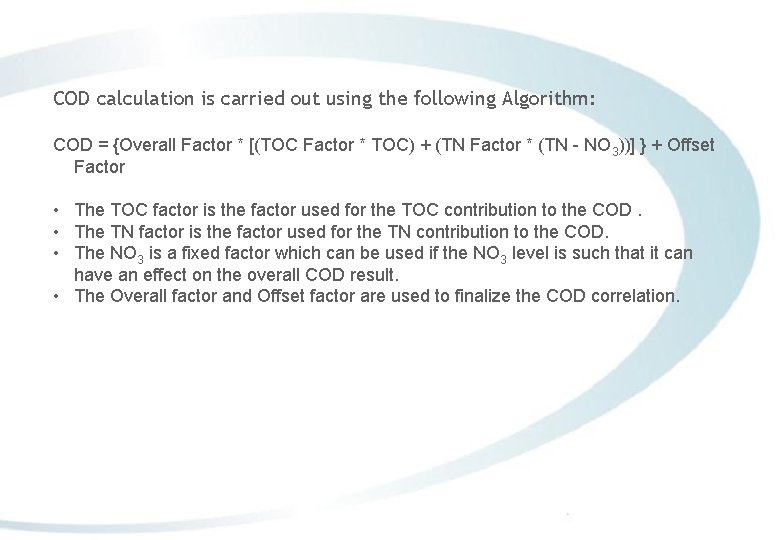
COD calculation is carried out using the following Algorithm: COD = {Overall Factor * [(TOC Factor * TOC) + (TN Factor * (TN - NO 3))] } + Offset Factor • The TOC factor is the factor used for the TOC contribution to the COD. • The TN factor is the factor used for the TN contribution to the COD. • The NO 3 is a fixed factor which can be used if the NO 3 level is such that it can have an effect on the overall COD result. • The Overall factor and Offset factor are used to finalize the COD correlation.
Oxidation Chemistry and Recoveries.
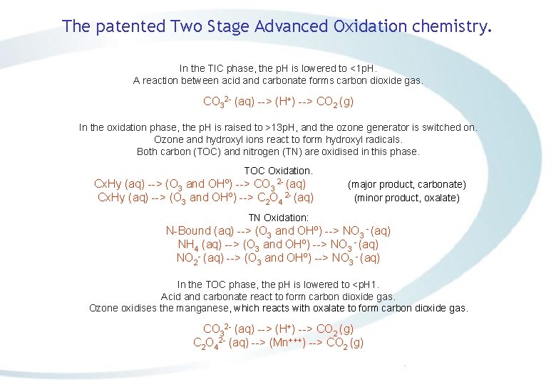
The patented Two Stage Advanced Oxidation chemistry. In the TIC phase, the p. H is lowered to <1 p. H. A reaction between acid and carbonate forms carbon dioxide gas. CO 32 - (aq) --> (H+) --> CO 2 (g) In the oxidation phase, the p. H is raised to >13 p. H, and the ozone generator is switched on. Ozone and hydroxyl ions react to form hydroxyl radicals. Both carbon (TOC) and nitrogen (TN) are oxidised in this phase. TOC Oxidation. Cx. Hy (aq) --> (O 3 and OHº) --> CO 3 2 - (aq) Cx. Hy (aq) --> (O 3 and OHº) --> C 2 O 4 2 - (aq) (major product, carbonate) (minor product, oxalate) TN Oxidation: N-Bound (aq) --> (O 3 and OHº) --> NO 3 - (aq) NH 4 (aq) --> (O 3 and OHº) --> NO 3 - (aq) NO 2 - (aq) --> (O 3 and OHº) --> NO 3 - (aq) In the TOC phase, the p. H is lowered to <p. H 1. Acid and carbonate react to form carbon dioxide gas. Ozone oxidises the manganese, which reacts with oxalate to form carbon dioxide gas. CO 32 - (aq) --> (H+) --> CO 2 (g) C 2 O 42 - (aq) --> (Mn+++) --> CO 2 (g)
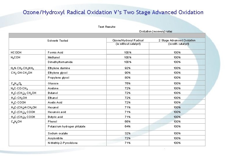
Ozone/Hydroxyl Radical Oxidation V’s Two Stage Advanced Oxidation Test Results Oxidation (recovery) rates Solvents Tested Ozone/Hydroxyl Radical (ie without catalyst) 2 Stage Advanced Oxidation (ie with catalyst) HCOOH Formic Acid 100% H 3 COH Methanol 100% Dimethylformamide 100% H 2 N-CH 2 NH 2 Ethylene diamine 92% 100% CH 2 -OH-CH 2 OH Ethylene glycol 90% 100% Propylene glycol 80% 100% C 6 H 12 O 6 Glucose 76% 100% H 3 C-CO-CH 3 Acetone 72% 100% H 3 C-(CH 2)2 -CH 2 OH Butanol 72% 100% H 3 C-CH 2 OH Ethanol 72% 100% H 3 C-COOH Acetic Acid 72% 100% H 3 C-(CH 2)4 -CH 2 OH Hexanol 71% 100% H 3 C-(CH 2)4 -COOH Hexanoic acid 71% 100% H 3 C-(CH 2)2 -COOH Butyric acid 71% 100% C 6 H 5 OH Phenol 66% 100% Potassium hydrogen phtalate 64% 100% Sodium oxalate 32% 100% Acrylonitrile 72% 100% N-Methly-2 -Pyrrolidone 71% 100%
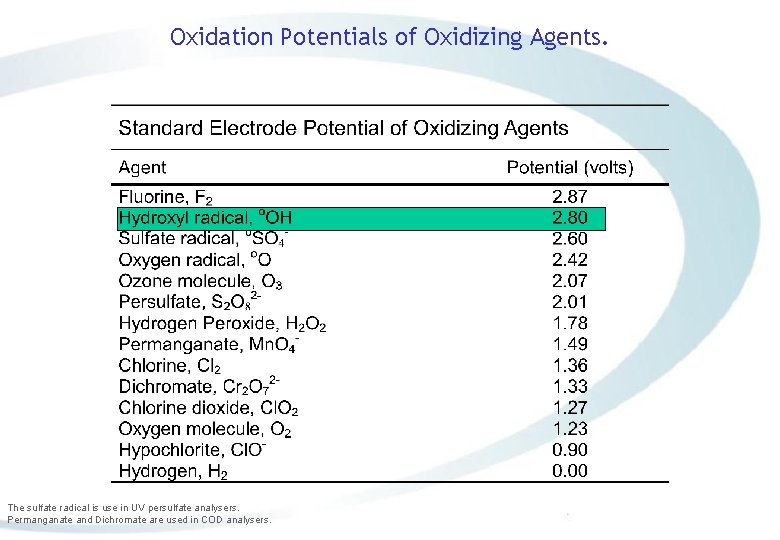
Oxidation Potentials of Oxidizing Agents. The sulfate radical is use in UV persulfate analysers. Permanganate and Dichromate are used in COD analysers.
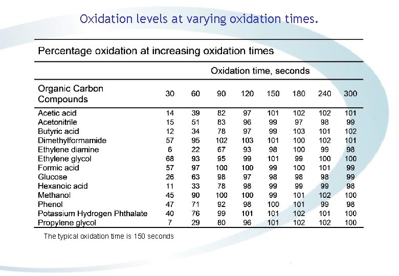
Oxidation levels at varying oxidation times. The typical oxidation time is 150 seconds
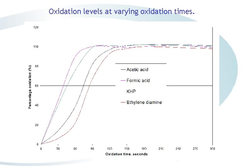
Oxidation levels at varying oxidation times.
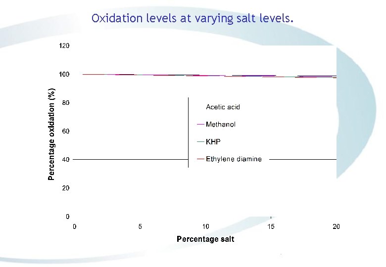
Oxidation levels at varying salt levels.

Analyzer Applications, Advantages and Disadvantages.
Advantages and Disadvantages of the Bio. Tector. Advantages: v Self cleaning oxidation without filtration. v Rugged sampling with a minimum 3 mm ID sample tube capable of handling particulates up to 2 mm. v Constructed using robust materials such as Hastelloy, Teflon, and Kalrez. This enables the Bio. Tector to withstand a wide variety of corrosive and toxic process fluids. v The Bio. Tector can operate safely in hazardous environments: i) It can analyse toxic process fluids without venting them to atmosphere. ii) The Bio. Tector can be purged for classified areas. iii) The Bio. Tector can analyse high pressure samples. Disadvantage: v More expensive to manufacture.
Bio. Tector installations. Industries, which have been using the Two Stage Advanced Oxidation technology for more than 10 years (over 600 units installed worldwide to date 2009) v Dairy processing plants where the effluents are high in fats, sugar and protein. v Chemical plants and applications where the process streams are high in salt and contain volatile organics. v Refineries where wastewaters contain oil, calcium and salts. v Municipal treatment plants where the wastewaters have high turbidity and particulates. v Airports where the surface water contains de-icing chemicals, particulates and salts (extremely high Organic loads). v Pulp and paper industries where wastewater contain fibrous materials and particulates. v Pharmaceutical industries where the waste streams contains a wide variety of chemicals.
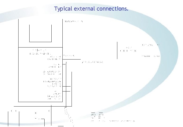
Typical external connections.
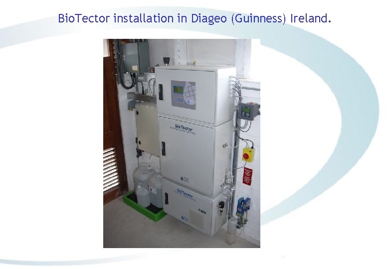
Bio. Tector installation in Diageo (Guinness) Ireland.
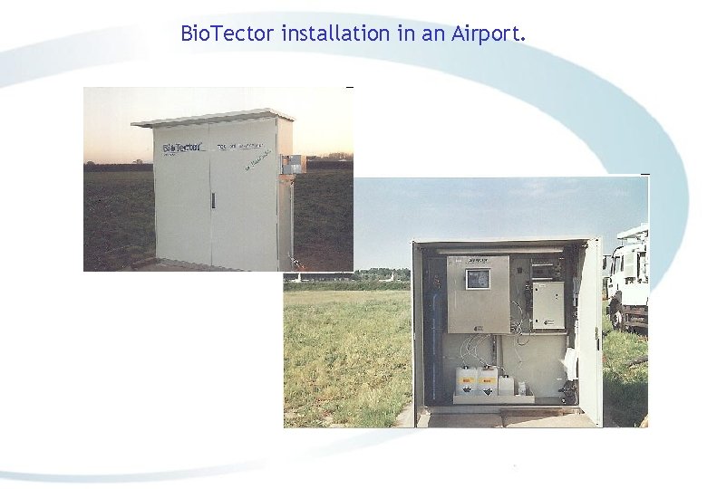
Bio. Tector installation in an Airport. Photo required
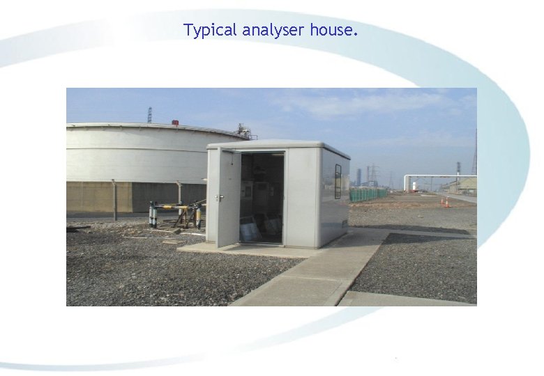
Typical analyser house.
SUMMARY ü Complete oxidation of the sample with hydroxyl radicals. ü Representative sample without any filtration (up to 2 mm soft particulates). ü Self cleaning technology. ü High reliability: 86, 000 measurements per annum and over 99% on-line time. ü Low Maintenance: 6 month service intervals. ü No calibration requirement between services. ü No interference from salts or Calcium. ü Automatic range selection and multi-streaming. ü Programmable Analysis Modes: TIC & TOC, TC, VOC, TC-TIC, TN and in addition TPR, TP modules are available. ü Analyse wide range of effluents containing fats, oils, salts, de-icing chemicals, particulates, fibrous materials.
Bio. Tector Installations • There are over 750 Bio. Tector’s installed world wide, many of which are in applications which would not have been possible with conventional technologies.
- Slides: 86