THE BEER GRID TEAM 13 Edgar Alastre EE
 | Jonathan Chang (Cp. E) |")
THE BEER GRID TEAM 13: Edgar Alastre (EE) | Jonathan Chang (Cp. E) | Colton Myers (EE) | Ashish Naik (Cp. E )
. • Beer Pong most")
Motivation • Today's devices are getting “ smarter” (Devices Interact). • Beer Pong most popular game in social gatherings. • Modernize Beer Pong. • Improve experience with embedded systems. • Fun but challenging Senior Design project. + = Beer GRID
 which")
Objectives RGB LED Array • Drive 80 RGB LED (80 Pixel “Grid” Display) which are individually controlled and responds from inputs of the Sensor array. These inputs are event triggered. Sensor Array • Detect contact of ball or object into the “main” area of the table. RGB LED Array Sensor Array Ball Cleaner Cup Display

Objectives Cup Display System • Detects cup which translates into games score sent to Smartphone App • App will include users profiles that track wins and losses as well as in-game score tracking. Ball Cleaner System • Allows user to clean regulation sized beer pong balls. RGB LED Array Sensor Array Ball Cleaner Cup Display

Specifications Component Parameter Design Specification Table Spilled Liquid Withstand 6 oz w/o Damage Ball Cleaner Cleaning Routine 2 Consecutive Beer Pong Balls Impact Sensor Array Responsiveness Real Time RGB LED Array Color density 64 Different Colors RGB LED Array Control Specification Independently Control Each LED PSU Power Specification 90 Watts with 5 V and 10 V outputs Smartphone/PC App Controllability Full Control/Customization of Table

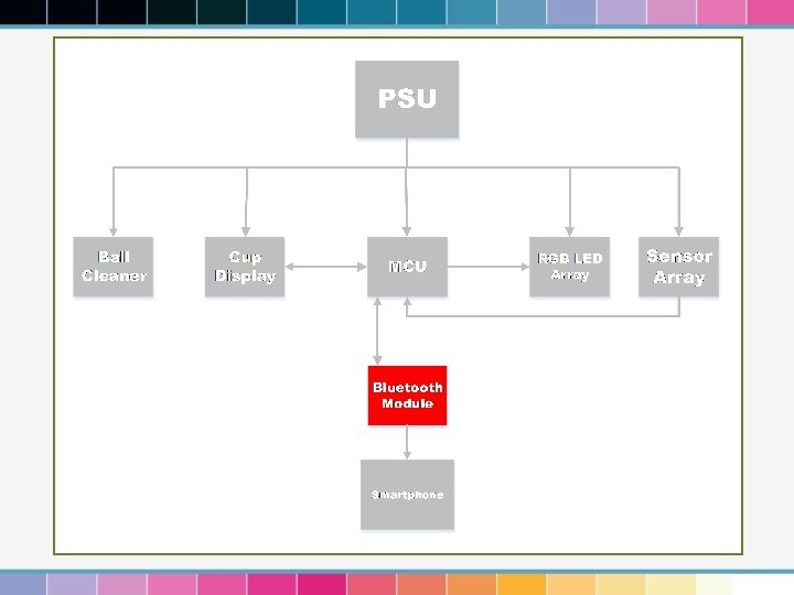
Block Diagram

Block Diagram

m. CU Selection Criteria: • At least 128 k. Bytes of flash memory • At least 44. 1 MHz frequency • SPI compatible for IC selection • Recommended: 5 V I/O Voltage Selection: ATSAM 3 X 8 E Microcontroller • 84 -MHz 32 -bit ARM Cortex M 3 • 512 k. Bytes of flash memory • 6 x SPI, 4 x I 2 C, 1 x UART • Operating Voltage : 1. 62 – 3. 6 v

EXPERIMENT BOARD Arduino UNO • Easy-to-use IDE to learn how to program ICs used in project • Vast amount of resources available online • Runs at 5 V and also includes SPI -> Essential • Team had Exp. Board available (Free) Arduino DUE • Powered by MCU of choice • Has more pins than UNO • Compatible with Arduino IDE • Runs on 3. 3 V • Low cost: 15. 99 USD

ide • Well received interface design • Specifically designed for Arduino experiment boards

The LED Array

LED Array DESIGN DETAILS • Microcontroller only has limited amount of input/outputs pins. • Impossible to drive 80 RGB LEDs without the need of a multiplex or IC. Solutions: • Multiplexing or Charlieplexing – Requires extensive and precise wiring • Shift Register – Requires extensive amount of resistors given high amount of LEDs • LED Driver – Integrated Circuit specialized in Driving tons of LEDs

LED Driver TLC 5940 From Texas Instruments • 16 Output channels • Effectively drive 5 RGB LEDS per TLC 5940 • 12 bit (4096 Steps) Grayscale PWM Control • Higher color resolution than PWM included in MCU • Drive Capability (Constant-Current Sink) • Allows us to have fewer electronic components per LED • Serial Data Interface • Requires SPI to fully control • 30 Mhz Data Rate • Useful when having lots of RGB LEDs -> Our Case. • Can be configured in Cascade mode • Essential for our project

LED Driver TLC 5940 From Texas Instruments Design Constraints by Choice: • Can only use Common anode RGB LEDs • 5 mm Common anode RGB LED 20 m. A of max current

LED Driver schematic

LED Driver schematic Cascaded
 • Arranged")
LED Array Program Structure • Pixel Nodes • One per pixel (80) • Arranged as a matrix • Holds current state information • Used to coordinate pixel reactions Led. Node id. Number current blinking off *north *east *south *west

LED Array Program Structure • Pattern Programming • Cascade effect • Blinking effect • Color Fade • Color Vanish Led. Node Pattern Class id. Number current blinking off *north *east *south *west

The Sensor Array

Sensor Array design details • Similar Problem as RGB LED Array (Extend our I/O Pins of MCU) • Require Electronic component that can detect nearby object (Impact of Beer Pong Ball) Solution: • Shift Register IC to extend amount of I/O Pins of MCU • Infrared Proximity sensor to detect impact of Beer Pong Ball • 74 HC 165 Shift Registers • TCRT 5000 L infrared sensor

Infrared Sensor TCRT 5000 L from Vishay Semiconductors • Includes IR Emitter and Receiver in a single package • Convenient for project size • Low Cost • Accurate detection parameter for our project. TCRT 5000 L Wiring Schematic

Shift Register 74 HC 165 Shift Register from NXP • 8 -bit Serial-in Shift Register • • Creates more output pins for use Allow 8 IR Proximity Sensors per IC • Synchronous Serial Input • Communicates via SPI • Allows to be Cascaded • Essential to drive tons of sensors 74 HC 165 Configured in Cascade Schematic

Sensor Array Program Structure • Signals used as input • Switch between 1 and 0 • Specific signals per pixel (80) • May require semaphores

The Cup Display System

Cup Display System • • Uses components from LED and Sensor Array: • RGB LEDs • Infrared Sensors • LED Drivers • Shift Registers Detects the removal of cups Determines score based on cups presence in table RGB LED part of “Theme Scheme” set by user Cup Display

Bluetooth Module HC-05 RS 232 from Inno. Gear • Allows wireless connection with Smartphone • Input Power 3. 3 -6 V • Compatible with our Microcontroller • Easy to program

The App

Smartphone App § Smartphone App will keep track of current game being played. (How many cups are left on each player’s side) § Will keep an updated record of each player’s wins losses. § Keep a queue of the players to determine who will play next. § Shows work in progress

Smartphone App O S Choices Android § Prior experience developing an Android application § Cheaper to develop for Choice: Android i. OS § No experience in developing on i. OS § Requires more money than android to start developing Windows § Nobody uses a Windows phone

Smartphone App IDE Android Studio Eclipse • Android Studio is the official Android application development IDE. • Android studio allows better testing with AVM • Choice : Android Studio

Smartphone App Use Case diagram

Smartphone App Class Diagram

The Ball Cleaner

Ball Cleaner BLOCK DIAGRAM

Ball Cleaner

Ball Cleaner microcontroller ATmega 328 P Specifications MSP 430 F 5529 Manufacturer Atmel Texas Instruments Max Operating Freq. 20 MHz 25 MHz Flash Memory 32 KB 128 KB RAM 2 KB 8 KB # of Channels 16 16 I/O Pins 23 63 Timers 3 4 Operating Voltage 1. 8 - 5. 5 Volts 1. 8 – 3. 6 Volts Applications Arduino Uno Model MSP-EXP 430 F 5529 LP

Ball Cleaner sensors Specifications Q 12 AB 6 FF 50 TCRT 5000 Manufacturer Banner Vishay Sensing Method Proximity Reflective Max Range 50 mm 15 mm Voltage Rating 10 -30 V 1. 5 V (Forward Voltage) 5. 0 V (Reverse Voltage) Current Rating 50 m. A 60 m. A (Forward Current) Pros Simple Wiring Shorter Range Cons Higher Voltage Input More Complex

Sensor wiring Banner. com

Ball Cleaner fans 41851 Bilge Blower 41841 Bilge Blower 140 Bilge Blower Manufacturer Seachoice Rule Intake Diameter 3 inches 4 inches 3 inches Exhaust Diameter 3 inches 4 inches 3 inches Length 8 inches 5 -3/4 inches 3 -1/4 inches Flow Rate 170 CFM 240 CFM 135 CFM Hose Connections Yes No Voltage 12 VDC 12 VDC 13. 6 VDC Current 4. 5 Amps 2. 9 Amps Price $20. 89 $21. 87 Specifications

Ball cleaner schematic

Ball cleaner schematic

Ball cleaner schematic

The Power Supply Unit

Power Supply Unit ATX Specifications Manufacturer Rosewill Voltage Output 3. 3, 5, 12 Volts Current Output 24 A, 30 A, 18 A Maximum Output Power 300 Watts Efficiency 60 % Price $29. 99

Table STRUCTURE

Printed circuit boards

Printed circuit boards MAIN CIRCUIT BOARD -92 Components

Printed circuit boards LED DRIVERS AND SHIFT REGISTERS SCHEMATIC

Printed circuit boards 5 LED DRIVERS, 4 SHIFT REGISTERS. 6 MADE

Bill of materials Parts Bluetooth TLC 5940 LED Driver 74 HC 165 Shift Register Common Anode LED Infrared Sensor 4 Color RGB extension Cable Protoboard Resistors 2 -pin connectors 4 -pin connectors PCB Table materials Plexiglass Bilge Blower Power Supply Proximity Sensor DPDT Relay SPDT Relay Grand Total Amount Price Total 1 $3. 90 17 $6. 98 $118. 66 35 $1. 88 $65. 80 80 $0. 07 $5. 60 80 $0. 34 $27. 0 4 $11. 00 $40 10 $2. 00 $20. 00 $30 80 $0. 44 $35. 20 80 $0. 40 $32 $130 $100 $40 1 $20. 89 $35 2 $76 $152 1 $3. 95 2 $3. 50 $7 $1033. 41 Grand Total: $1033. 41

Labor Division • Edgar Alastre • • Ashish Naik • Primary Responsibility: Programming Table • Secondary Responsibility: Programming App • Colton Myers Primary Responsibility: Circuit Design Secondary Responsibility: Programming Table Jonathan Chang • Primary Responsibility: Programming App • Secondary Responsibility: Programming Table • • Primary Responsibility: Power Supply, Table, and Ball Cleaner Design/Construction Secondary Responsibility: Circuit Design

hope YOU ENJOYED

QUESTIONS SECTION
- Slides: 54