The Basics of Logic Design Goal Create an

The Basics of Logic Design
 • The simplest “smart” unit in a")
Goal: Create an Arithmetic Logic Unit (ALU) • The simplest “smart” unit in a processor • Performs basic operations on 32 bit inputs

Gates, Truth Tables, and Logic Equations • Signals: • Asserted – 1/True +5 V • De-asserted – 0/False 0 V • Blocks: • No memory – combinatorial logic • With memory (state) – sequential logic • Truth table: • Describes a combinatorial function • All possible combinations of input values to output
, AND (⋅ ), NOT • Laws: •")
Boolean Algebra • Operations • OR (+), AND (⋅ ), NOT • Laws: • • • Identity: A+0 = A and A⋅1 = A. Zero and One: A+1 = 1 and A⋅0 = 0. Inverse: A+A = 1 and A⋅A = 0. Commutative: A + B = B + A and A ⋅ B = B ⋅ A. Associative: A + (B + C) = (A + B) + C and A ⋅ (B ⋅ C) = (A ⋅ B) ⋅ C. Distributive: A⋅(B+C) = (A⋅B)+(A⋅C) and A+(B⋅C) = (A+B)⋅(A+C). • De Morgan Theorem: • (A+B)’=A’·B’ • (A·B)’=A’+B’
 logical sum • AND")
Gates • Implements the simplest logic function: • OR (+) logical sum • AND (⋅ ) logical product • NOT (‘) negation (A’+B)’ = A’*B

In class problem • Prove that the following two equations are equivalent using De. Morgan theorem: • E = ((A⋅B)+(A⋅C)+(B⋅C))⋅(A⋅B⋅C)’ • D = (A⋅B⋅C’)+(A⋅B’⋅C)+(A’⋅B⋅C)

Decoder • Converts binary information from n inputs to a maximum of 2 n outputs A B 0 1 2 3 0 0 1 0 0 1 0 0 0 12 I 0 I 1 CS 210 Computer Organization D 0 D 1 D 2 D 3 7

Decoder From http: //en. wikipedia. org/wiki/Decoder CS 210 Computer Organization 8

Encoder • The opposite of a decoder. It has up to 2 n input lines only one of which will be high and n output lines which represent the binary code for the inputs. base 5 to binary encoder D 0 D 1 D 2 D 3 D 4 b 2 b 1 b 0 CS 210 Computer Organization Sometimes a Valid output bit is used to distinguish between a valid 0 state and a no-active-input state. 9

Encoder From http: //en. wikipedia. org/wiki/Priority_encoder#Simple_encoder CS 210 Computer Organization 10

Multiplexor • Basic logic function • Selects one input to output • How many selection bits for n-bit input? E S 1 S 0 Z 0 x x 0 1 0 0 I 0 1 I 1 1 1 0 I 2 1 1 1 I 3 E I 0 I 1 I 2 I 3 Z S 1 S 0

Demultiplexor • The opposite of a multiplexer. • It receives input on a single line, transmitting it to one of 2 n possible output lines, depending on a set of n select lines O 0 O 1 O 2 O 3 I S 1 S 0

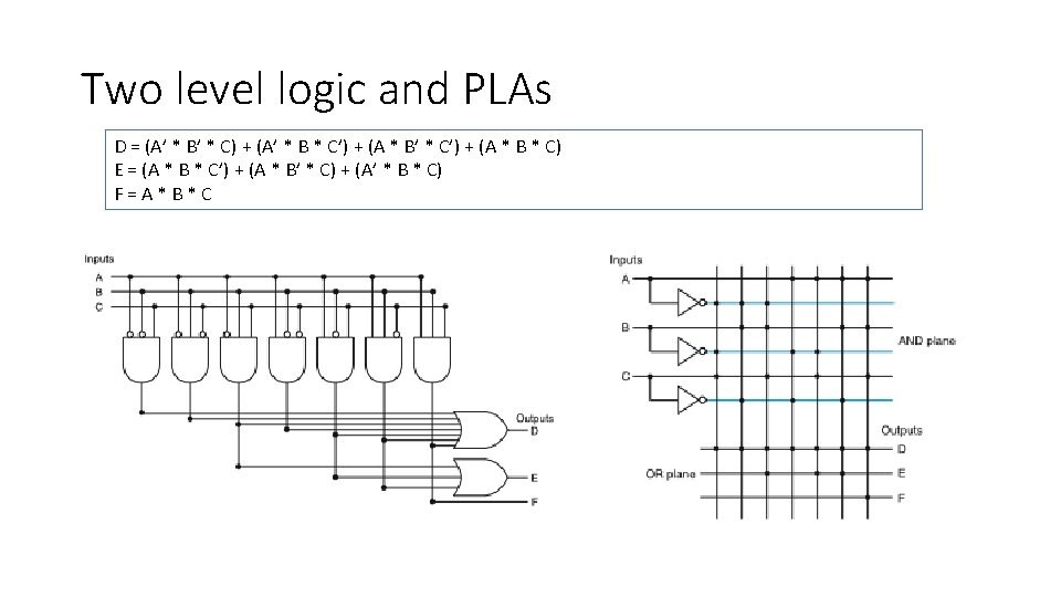
Two level logic and PLAs Tidy, formulaic way to create a circuit diagram for a set of logic functions written in sumof-products form. A B C D 0 0 0 1 1 0 0 0 1 1 1 1 0 0 1 1 What is D in sum-of-product form? 13

A 1 -bit ALU AND, OR, a+b

1 bit adder a b Carry In Carry Out Sum 0 0 0 0 1 0 1 0 1 1 1 0 0 0 1 1 0 1 1 1 Carry. Out = b*Carry. In + a*b*Carry. In Carry. Out = b*Carry. In + a*b

1 bit adder a b Carry In Carry Out Sum 0 0 0 0 1 0 1 0 1 1 1 0 0 0 1 1 0 1 1 1 What is the formula for Sum output? Implement it with gates.

32 -bit ALU

- Slides: 19