The Art of Digital Design and Fast Adder

 • Techniques for tackling dependency aspects")


 • Concept of generate Gk for k bits: Gk is")
 • In practice, instead of generating generates and propagates in")
")

- Slides: 28
The Art of Digital Design and Fast Adder Circuits Lecture Notes # 4 Shantanu Dutt Electrical & Computer Eng. University of Illinois at Chicago
Outline • Different dependency aspects in divide-&conquer (D&C) • Techniques for tackling dependency aspects in D&C • Application to adder designs---ripple carry, treebased carry-lookahead, carry select
Dependency Aspects in D&C Legend Stitch-up of solns to A 1 and A 2 to form the complete soln to A Root problem A D&C tree arc Data flow arc Subprob. A 1, 1 A 1, 2 Subprob. A 2, 1 A 2, 2 • Q: Is there a data dependency between A 1 and A 2, i. e. , does solution of A 2 depend on some o/p generated by A 1 or vice versa? • If there is no dependency, then A 1 and A 2 can be solved independently and some stitch-up logic used to combine the o/ps of A 1 and A 2 to obtain the o/p of A. Example design problems are n-bit comparison, sorting of n #s • If there is a dependency between A 1 and A 2 there a few strategies that can be used to design such circuits---note that a stitch-up logic can still be needed for D&C partitioning w/ dependency of a design problem.
Dependency Aspects in D&C The Wait Strategy Root problem A Subprob. A 2 Subprob. A 1 Data flow • Strategy 1: Wait for required o/p of A 1 and then perform A 2, e. g. , as in a ripple-carry adder: A = n-bit addition, A 1 = (n/2)-bit addition of the L. S. n/2 bits, A 2 = (n/2)-bit addition of the M. S. n/2 bits • No concurrency between A 1 and A 2: t(A) = t(A 1) + t(A 2) + t(stich-up) = 2*t(A 1) + t(stich-up) if A 1 and A 2 are the same problems of the same size (w/ different i/ps)
Dependency Aspects in D&C The “Design-for-all-cases and Select” Strategy Root problem A 00 01 10 Subprob. A 1 Subprob. A 2 I/p 00 Subprob. A 2 I/p 01 I/p 10 4 -to-1 Mux • Strategy 2: For a k-bit i/p from A 1 to A 2, design 2**k copies of A 2 each with a different hardwired k-bit i/p to replace the one from A 1. • Select the correct o/p from all the copies of A 2 via a (2**k)-to-1 Mux that is selected by the k-bit o/p from A 1 when it becomes available • E. g. , carry-select adder • t(A) = max(t(A 1), t(A 2)) + t(Mux) + t(stichup) = t(A 1) + t(Mux) + t(stitch-up) if A 1 and A 2 are the same problems Select i/p I/p 11 11 Subprob. A 2 • Other variations---“Predict Strategy”: Have a single copy of A 2 but choose a highly likely value of the k-bit i/p and perform A 1, A 2 concurrently. If after k-bit i/p from A 1 is available and selection is incorrect, re-do A 2 w/ correct available value. • t(A) = p(correct-choice)*max(t(A 1), t(A 2)) +[(1 -p(correct-choice)]*t(A 2) + t(Mux) + t(stich-up), where p(correct-choice) is probability that our choice of the k-bit i/p for A 2 is correct • Need a completion signal to indicate when the final o/p is available for A; assuming worstcase time (when the choice is incorrect) is meaningless is such designs
Dependency Aspects in D&C---The “Lookahead” Strategy Concept Example of an unstructured logic for A 2 v’ x’ u v x w’ x yw z’ a 1 u’ x a 1 v’ x’ u v x w’ x yw z’ u’ x Root problem A Subprob. A 1 Subprob. A 2_dep Data flow A 2_indep or A 2_lookahd A 2_indep Critical path after a 1 avail (8 -unit delay) a 2 Critical path after a 1 avail (4 -unit delay) A 2_dep a 2 • Strategy 3: Redo the design of A 2 so that it can do as much processing as possible that is independent of the i/p from A 1 (A 2_indep = A 2_lookahd). This is the “lookahead” computation that prepares for the final computation of A 2 (A 2_dep) that can start once A 2_indep and A 1 are done. • t(A) = max(t(A 1), t(A 2_indep)) + t(A 2_dep) + t(stitch-up) • E. g. , Carry-looakahead adder --- does lookahead computation; also looakahead compuattion is associative, so doable in (log n). Overall computation is also doable in (log n) time. • A less structured example: Let a 1 be the i/p from A 1 to A 2. If A 2 has the logic a 2 = v’x’ + uvx + w’xy + wz’a 1 + u’xa 1. If this were implemented using 2 -i/p AND/OR gates, the delay will be 8 delay units (1 unit = delay for 1 i/p) after a 1 is available. If the logic is re-structured as a 2= (v’x’ + uvx + w’xy) + (wz’ + u’x)a 1, and if the logic in the 2 brackets are performed before a 1 is available (these constitute A 2_indep), then the delay is only 4 delay units after a 1 is available. a 1
Adder Circuits—From Slow to Fast
Tree CLA Adders • First of all, can we generate multi-bit P, G signals formed from single-bit ones? • Secondly, can we generate them fast, say, in (log n) time using a tree-structured circuit? • The answer is “Yes” to both Qs. For the 2 nd Q, the answer is “Yes” since, P, G operations are associative! • Concept of the propagate Pk for k bits: Pk is 1 under the conditions that the carry into the least-significant of the k bits should be the carry-out of the most-significant of the k bits. In terms of the 1 -bit pi’s this happens if and only if all the k bits are in “propagate mode”, i. e. , for all i, 1 <= i <= k, pi = 1. Thus Pk = pk-1 pk-2 ……… p 0. Since “and” is associative, the propagate is an associative operation and can thus be generated using a tree-circuit in log n time.
Tree CLA Adders (contd) • Concept of generate Gk for k bits: Gk is 1 under the conditions that the carry-out of the k bits should be 1 irrespective of the carry-in to the k bits • For k=2, this happens whenever g 1=1 or (g 0=1 and p 1=1): G 2 = g 1 + p 1 g 0 • Now consider k=3. Conceptually speaking, G 3=1 iff g 2=1 or G 2(bits 1 -0)=1 and p 2=1. This operates on the 1 -bit g and 1 -bit p for bit 2 and the 2 -bit G for bits 1 & 0: G 3 = g 2 + p 2 G 2(1 -0) = g 2 + [p 2 (g 1 + p 1 g 0)] = g 2 + p 2 g 1 + p 2 p 1 g 0 • However, G 3=1 iff G 2(bits 2 -1)=1 or g 0=1 and P 2(bits 2 -1)=1. This operates on the 2 -bit G and P for bits 2 & 1 and the 1 -bit g and 1 -bit p for bit 2: G 3 = G 2(2 -1) + P 2(2 -1)g 0 = [g 2 + p 2 g 1] + [p 2 p 1 g 0] = g 2 + p 2 g 1 + p 2 p 1 g 0 (same as above!) • In other words (g 2, p 2) gen [(g 1, p 1) gen (g 0, p 0)] = [(g 2, p 2) gen (g 1, p 1)] gen (g 0, p 0) --you can also come to the same conclusion using a truth table (TT). • Hence generate (gen) is also an associative operation and can thus be generated using a treecircuit in log n time. p 2 g 2 p 1 g 1 p 0 g 0 p 3 g 3 p 2 g 2 p 1 g 1 p 0 g 0 2 2 2 2 gen G 2(2 -1) G 2(1 -0) & gen gen G 2(1 -0) G 2(3 -2) gen gen G 3(2 -0) G 3 gen G 4 G 2(1 -0) gen G 4
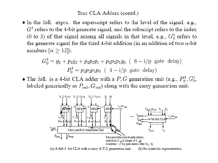
Tree CLA Adders (contd) • In practice, instead of generating generates and propagates in a binary tree using 2 - bit prop, gen operations, 4 -bit prop, gen operations are used as basic modules and the higher-level generate and propagates are generated using a 4 -ary tree. p 3 g 3 p 2 g 2 p 1 g 1 p 0 g 0 2 2 i. e. , G 4 = g 3 + p 3 g 2 + p 3 p 2 g 1 + p 3 p 2 p 1 g 0 4 -bit gen = gen Similarly for 4 -bit propagates: P 4 = p 3 p 2 p 1 p 0 G 2(1 -0) gen G 3(2 -0) gen G 4 (b) Basic 4 -bit (a) 4 -bit G generation (P, G)-module using 2 -bit G-operations • We thus have the following 4 -ary prop, gen (P, G) tree using 4 -bit (P, G) generation logic as the basic module (c) 4 -ary (P, G)-tree
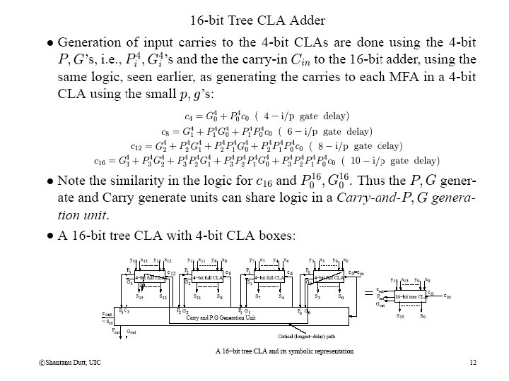
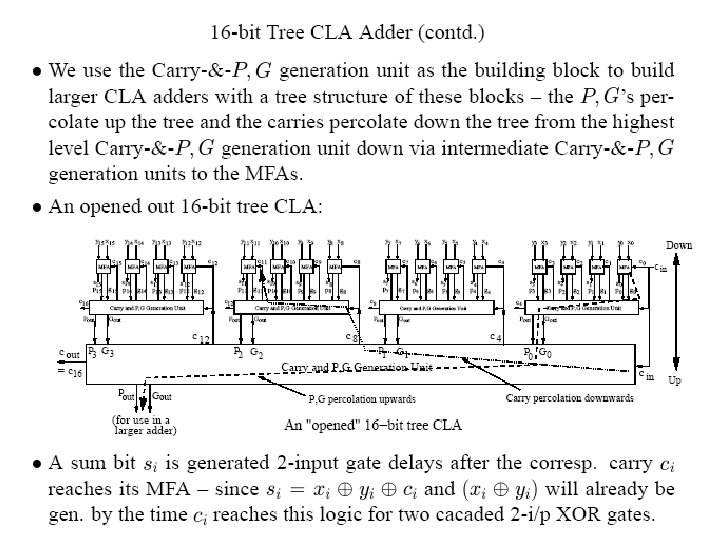
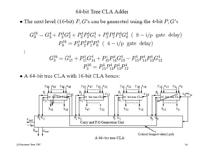
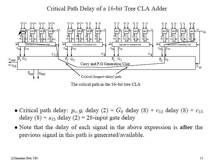
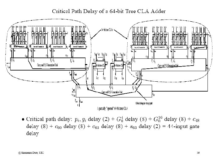
Tree CLA Adders (contd)