
THE AQUANTIS OCEANCURRENT TURBINE RENEWABLE ENERGY FROM MARINE
THE AQUANTIS OCEAN-CURRENT TURBINE RENEWABLE ENERGY FROM MARINE CURRENTS Blade Count Trade Study Update 11/29/2012 Ole Kils Aquantis Inc. Company Confidential and Proprietary – October 18 -19, 2011
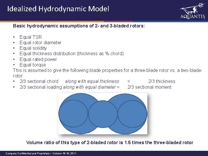
Idealized Hydrodynamic Model Basic hydrodynamic assumptions of 2 - and 3 -bladed rotors: • Equal TSR • Equal rotor diameter • Equal solidity • Equal thickness distribution (thickness as % chord) • Equal rated power • Equal torque This is assumed to give the following blade properties for a three-blade rotor vs. a two-bladerotor: • 2/3 sectional chord along with equal thickness = 2/3 thickness • 2/3 sectional loading along with equal diameter = 2/3 sectional moment Volume ratio of this type of 2 -bladed rotor is 1. 5 times the three-bladed rotor Company Confidential and Proprietary – October 18 -19, 2011
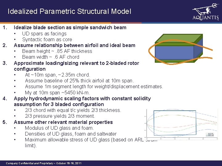
Idealized Parametric Structural Model 1. 2. 3. 4. 5. Idealize blade section as simple sandwich beam • UD spars as facings • Syntactic foam as core Assume relationship between airfoil and ideal beam • Beam height ~. 85 AF thickness • Beam width ~. 6 AF chord Approximate loading/sizing relevant to 2 -bladed rotor configuration • At ~10 m span, ~2. 35 m chord. • Assume baseline of 25% thick airfoil at 10 m span. • Assume 1 m segment length for weight/displacement estimates. • My at 10 m span ~5450 k. N-m. Apply hydrodynamic scaling factors with constant solidity assumption for 3 bladed configuration • 2/3 chord with equal t/c yields 2/3 thickness. • 2/3 pressure yields 2/3 moment. Assume other relevant material properties • Modulus of UD glass and foam. • Densities of UD glass, foam and saltwater • Maximum allowable stress of UD glass (based on ARL strain limit). Company Confidential and Proprietary – October 18 -19, 2011
Calculation approach 1. 2. Two variables were investigated: • % thickness at given chord and moment vs. rotor section wet weight and spar thickness. • Loading intensity at given 35% t/c vs. rotor section wet weight and spar thickness. Each configuration sets geometric or loading parameters and solves for spar cap thickness at design stress in the spars. Company Confidential and Proprietary – October 18 -19, 2011
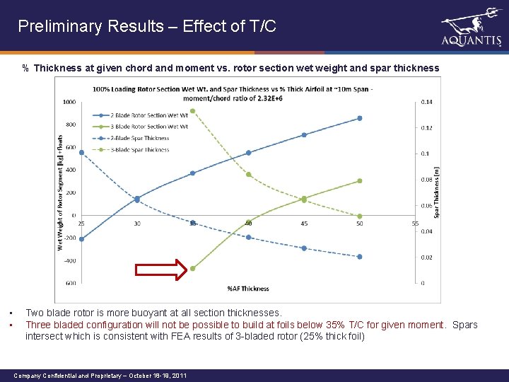
Preliminary Results – Effect of T/C % Thickness at given chord and moment vs. rotor section wet weight and spar thickness • • Two blade rotor is more buoyant at all section thicknesses. Three bladed configuration will not be possible to build at foils below 35% T/C for given moment. Spars intersect which is consistent with FEA results of 3 -bladed rotor (25% thick foil) Company Confidential and Proprietary – October 18 -19, 2011
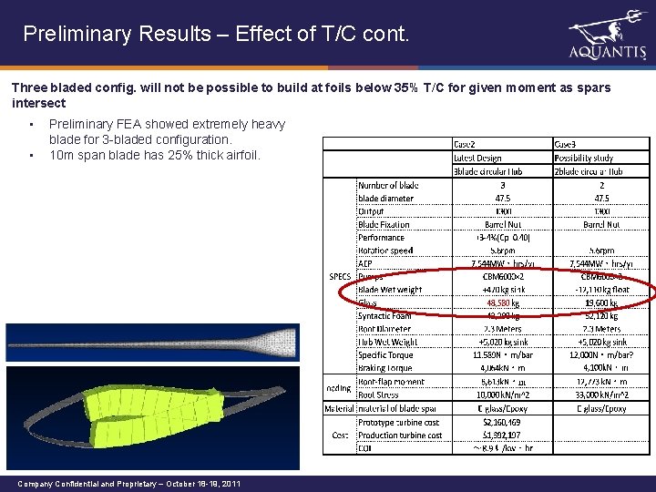
Preliminary Results – Effect of T/C cont. Three bladed config. will not be possible to build at foils below 35% T/C for given moment as spars intersect • • Preliminary FEA showed extremely heavy blade for 3 -bladed configuration. 10 m span blade has 25% thick airfoil. Company Confidential and Proprietary – October 18 -19, 2011
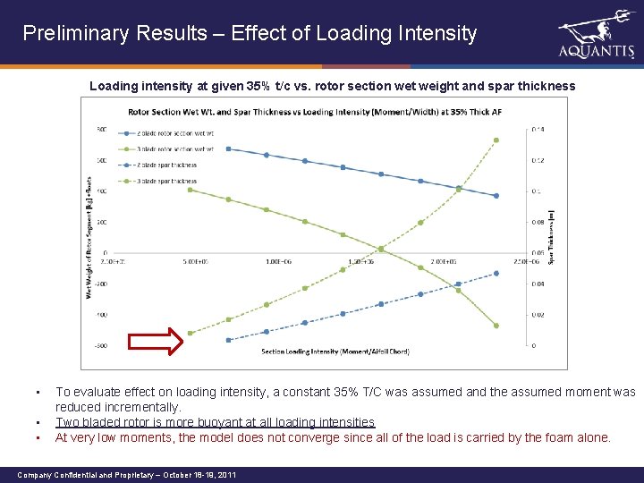
Preliminary Results – Effect of Loading Intensity Loading intensity at given 35% t/c vs. rotor section wet weight and spar thickness • • • To evaluate effect on loading intensity, a constant 35% T/C was assumed and the assumed moment was reduced incrementally. Two bladed rotor is more buoyant at all loading intensities At very low moments, the model does not converge since all of the load is carried by the foam alone. Company Confidential and Proprietary – October 18 -19, 2011
Take-Away & Next Steps For the given assumptions, a two-bladed rotor is more buoyant in all conditions investigated. Next Steps: • • Evaluate impact of sectional cost along with wet weight Cross-check hydrodynamic assumptions and their effect on system efficiency/power production. Check stress on foam. Assumed to be non-issue since modulus is dominated by spar. Expand model to include more accurate section calculator and be able to include multiple sections to begin thickness optimization studies Company Confidential and Proprietary – October 18 -19, 2011
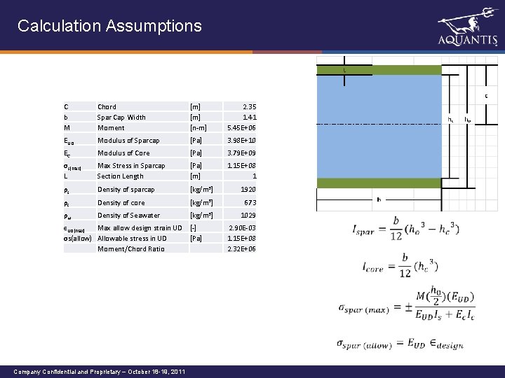
Calculation Assumptions C b M Chord Spar Cap Width Moment [m] [n-m] 2. 35 1. 41 5. 45 E+06 EUD Modulus of Sparcap [Pa] 3. 98 E+10 EC Modulus of Core [Pa] 3. 79 E+09 σs(max) L Max Stress in Sparcap Section Length [Pa] [m] 1. 15 E+08 1 ρs Density of sparcap [kg/m 3] 1920 ρc Density of core [kg/m 3] 673 ρw Density of Seawater [kg/m 3] 1029 ϵUD(max) Max allow design strain UD [-] σs(allow) Allowable stress in UD [Pa] Moment/Chord Ratio 2. 90 E-03 1. 15 E+08 2. 32 E+06 Company Confidential and Proprietary – October 18 -19, 2011
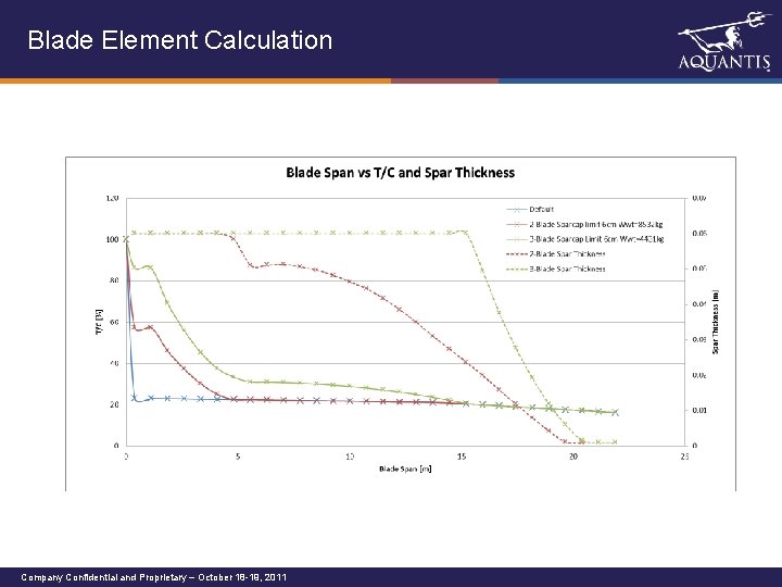
Blade Element Calculation Company Confidential and Proprietary – October 18 -19, 2011
- Slides: 10