
The 8051 Microcontroller hsabaghianb kashanu ac ir Microprocessors

The 8051 Microcontroller hsabaghianb @ kashanu. ac. ir Microprocessors 1 -1
8051 Interrupt hsabaghianb @ kashanu. ac. ir Microprocessors 1 -2
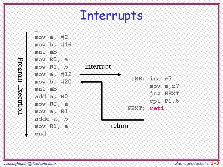
Interrupts Program Execution … mov a, #2 mov b, #16 mul ab mov R 0, a mov R 1, b mov a, #12 mov b, #20 mul ab add a, R 0 mov R 0, a mov a, R 1 addc a, b mov R 1, a end hsabaghianb @ kashanu. ac. ir interrupt ISR: inc r 7 mov a, r 7 jnz NEXT cpl P 1. 6 NEXT: reti return Microprocessors 1 -3
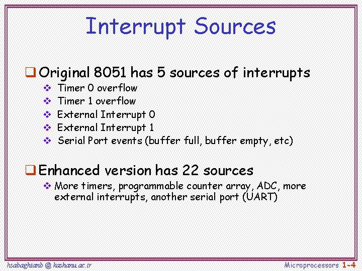
Interrupt Sources q Original 8051 has 5 sources of interrupts v v v Timer 0 overflow Timer 1 overflow External Interrupt 0 External Interrupt 1 Serial Port events (buffer full, buffer empty, etc) q Enhanced version has 22 sources v More timers, programmable counter array, ADC, more external interrupts, another serial port (UART) hsabaghianb @ kashanu. ac. ir Microprocessors 1 -4
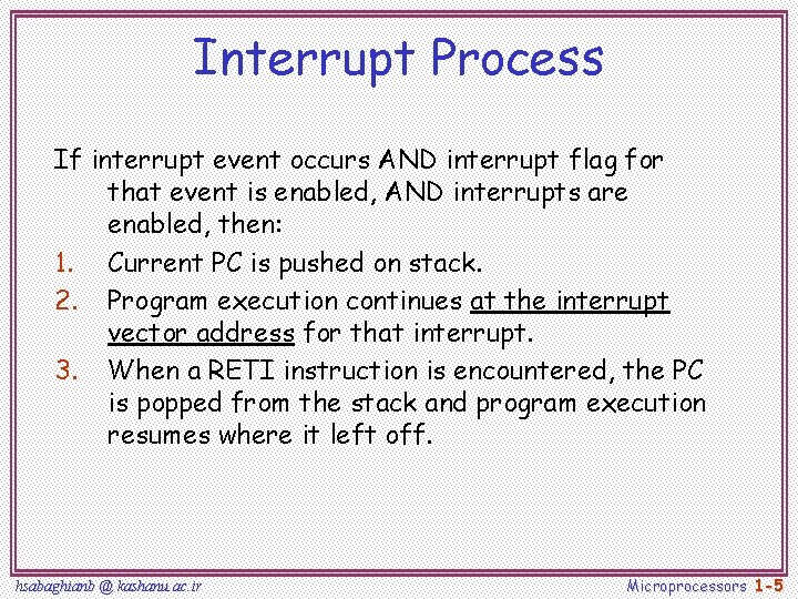
Interrupt Process If interrupt event occurs AND interrupt flag for that event is enabled, AND interrupts are enabled, then: 1. Current PC is pushed on stack. 2. Program execution continues at the interrupt vector address for that interrupt. 3. When a RETI instruction is encountered, the PC is popped from the stack and program execution resumes where it left off. hsabaghianb @ kashanu. ac. ir Microprocessors 1 -5
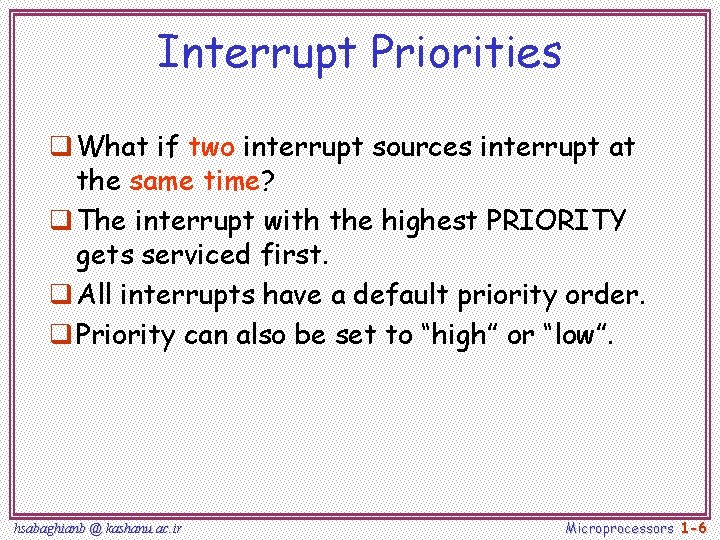
Interrupt Priorities q What if two interrupt sources interrupt at the same time? q The interrupt with the highest PRIORITY gets serviced first. q All interrupts have a default priority order. q Priority can also be set to “high” or “low”. hsabaghianb @ kashanu. ac. ir Microprocessors 1 -6
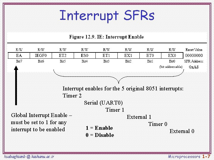
Interrupt SFRs Interrupt enables for the 5 original 8051 interrupts: Timer 2 Serial (UART 0) Timer 1 Global Interrupt Enable – External 1 must be set to 1 for any Timer 0 1 = Enable interrupt to be enabled External 0 0 = Disable hsabaghianb @ kashanu. ac. ir Microprocessors 1 -7
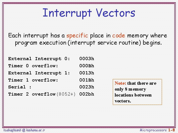
Interrupt Vectors Each interrupt has a specific place in code memory where program execution (interrupt service routine) begins. External Interrupt 0: Timer 0 overflow: External Interrupt 1: Timer 1 overflow: Serial : Timer 2 overflow(8052+) hsabaghianb @ kashanu. ac. ir 0003 h 000 Bh 0013 h 001 Bh 0023 h 002 bh Note: that there are only 8 memory locations between vectors. Microprocessors 1 -8
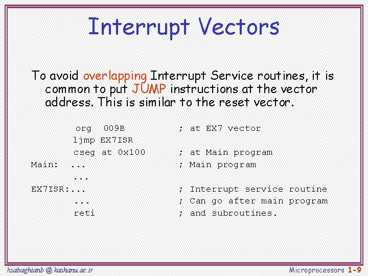
Interrupt Vectors To avoid overlapping Interrupt Service routines, it is common to put JUMP instructions at the vector address. This is similar to the reset vector. org 009 B ljmp EX 7 ISR cseg at 0 x 100 Main: . . . EX 7 ISR: . . . reti hsabaghianb @ kashanu. ac. ir ; at EX 7 vector ; at Main program ; Interrupt service routine ; Can go after main program ; and subroutines. Microprocessors 1 -9
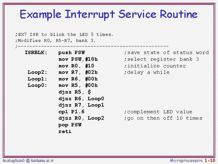
Example Interrupt Service Routine ; EX 7 ISR to blink the LED 5 times. ; Modifies R 0, R 5 -R 7, bank 3. ; -------------------------- ISRBLK: Loop 2: Loop 1: Loop 0: hsabaghianb @ kashanu. ac. ir push PSW mov PSW, #18 h mov R 0, #10 mov R 7, #02 h mov R 6, #00 h mov R 5, #00 h djnz R 5, $ djnz R 6, Loop 0 djnz R 7, Loop 1 cpl P 1. 6 djnz R 0, Loop 2 pop PSW reti ; save state of status word ; select register bank 3 ; initialize counter ; delay a while ; complement LED value ; go on then off 10 times Microprocessors 1 -10
- Slides: 10