The 80386 The 80386 K Raghunathan Chartered Engineer


 • Supports Virtual Memory upto 64 Tb. • Maximum size of")
 • Three Modes of Operation: – Real Mode: This is the")
 • Released in 1986. • Benchmarked at 4 MIPS (Million Instructions")


 – Virtual 86")


![Physical Memory Organisation (2) Physical Addresses [32 -bit] xx. . xx 00 xx. .](https://slidetodoc.com/presentation_image_h2/6afe346408209692e9b92eb5a98eb7d5/image-31.jpg "Physical Memory Organisation (2) Physical Addresses [32 -bit] xx. . xx 00 xx. .")


 • The 80386 has the necessary hardware circuitry, called the Paging")

 • However, it is not really necessary to keep entire programs in")
 • • Memory allocation is done in \"pages\" A page is a")
 • The 80386 allows us to keep a Page Table Directory capable")
 • The 1 K entries in the PTD/PT take 4 bytes each")

 • The Mth entry in the PT is at")
")


")
")

- Slides: 51
The 80386
The 80386 K. Raghunathan Chartered Engineer FIETE, MIE, MCSI, MISTE, MISTD, MIIMM Retd. Dy. Controller (R&D) [Mo. D]
Salient Features • • First 32 -bit microprocessor in the x 86 family 80286 architecture expanded for 32 bit operation 32 -bit Processor 32 -bit ALU, 32 -bit Registers, 32 -bit Data Bus, 32 bit Address Bus Uses 32 -bit address for memory and 16 -bit address for I/O ports Maximum physical memory 4 Gb. Maximum number of I/O ports 64 K. Built-in Memory Management Unit to support Segmentation, Paging and Virtual Memory.
Salient Features (2) • Supports Virtual Memory upto 64 Tb. • Maximum size of Segment 4 Gb. • Physical memory to be organised in four banks to enable 32 -bit read/write. • Uses 13 flags in the Flags register and 6 flags in the MSW. • New registers for managing Virtual Memory and Paging. • New "Debug" Registers provide Breakpoint facility to programmers. • 14 New Instructions. • Pipelining, by way of – 16 -byte Instruction Queue (aka Prefetch Buffer). – Code Queue (decoded instructions).
Salient Features (3) • Three Modes of Operation: – Real Mode: This is the Start-up mode. In this mode it behaves like a 8086, can access only 1 Mb memory in the address range 00000 h to FFFFFh with four 64 K segments, does not support multitasking/privilege levels/virtual memory/paging. (Same as in 80286). – Protected Mode: In this mode, it can access all 4 Gb memory with six segments of variable size (maximum 4 size 4 Gb), supports multitasking/privilege levels/virtual memory/paging. – Virtual 86 Mode: This is a new mode available in 80386 and later processors from Intel. This is a submode under Protected mode. In this mode, it provides virtual 1 Mb DOS Environment for DOS programs.
Salient Features (4) • Released in 1986. • Benchmarked at 4 MIPS (Million Instructions Per Second). • Packaging: 132 pin PGA(Pin Grid Array). • Contains 275, 000 transistors, using 1. 5 micron CHMOS Technology. • Three different speed models: 16/25/33 MHz.
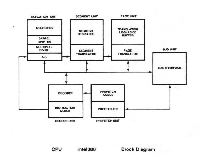
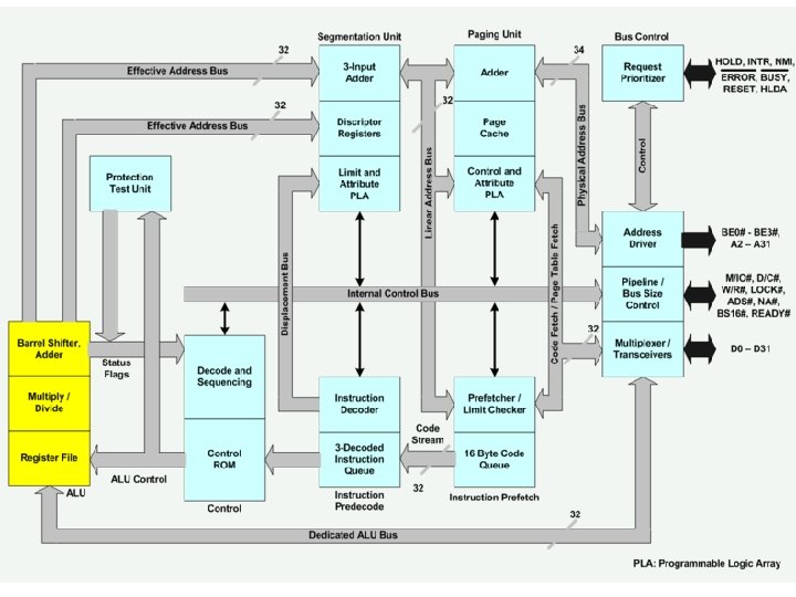
Architecture • 6 functional units – Bus Interface unit – Prefetch unit – Decode unit – Memory Management Unit, consisting of • Segmentation unit • Paging unit – Execution unit
Bus Interface Unit • Interfaces CPU with the other components of the computer system such as – Memory – Support chips – I/O interface chips • Enables data transfer and control of the system
Prefetch Unit • Fetches instructions from memory when Bus Interface unit is not executing a normal bus cycle • Uses an advance instruction fetch pointer to prefetch code from memory and stores it in a 16 byte temporary Instruction Queue called Prefetch Queue • This queue also acts as a buffer between the Prefetch unit and the Instruction Decode unit • Since the address generated by the Prefetch unit are linear, they must be translated to physical address by Paging unit before the prefetch bus cycle request can be sent to the Bus Interface unit
Decode Unit • Translates instructions from the Prefetch Queue into micro codes • The decoded instructions (micro codes) are stored in a Code Queue for processing by execution unit
Execution Unit • Operates on the decoded instructions, performing the steps needed to execute it • Contains Control Unit, Data Unit & Protection Unit • Control unit contains the microcodes and parallel hardware for fast multiply, divide and effective address calculation • Data unit carries out data operations required by the control unit • Data unit includes ALU, General Purpose Registers and a 64 -bit barrel shifter for performing multiple bit shifts in one clock • Protection Unit checks Privilege Levels, for possible violation of Access Rights
Memory Management Unit • Responsible for memory usage by multiple tasks without clash • Whenever a memory access is required (for prefetching the instructions, for reading/writing data), the EA (Effective Address) is sent to the Segmentation Unit for computation of memory address as envisaged in the instruction (by combining the EA with the Segment start address) • The segmentation unit combines EA and Segment start address and produces a Linear Address • This linear address is sent to the Paging Unit • The paging unit translates linear address into Physical Address and sends it to the bus interface unit – If paging is not enabled, the linear address produced by the segmentation unit is taken as the physical address and sent to BIU • Segmentation and Paging units also perform checks for violation of Segment/Page limits and generate exceptions (or sets up flags) in case of violations.
Register Set • Register Types – – – – General Purpose registers Instruction Pointer register Flags register Selector registers Descriptor Cache registers Control registers Debug registers Test registers • Size – Selector registers are 16 -bit – Descriptor cache registers are 64 -bit – All other registers are 32 -bit
General Purpose Registers
Instruction Pointer • EIP - 32 bits • In Real mode – the CPU behaves like 8086 – uses the lower 16 bits of EIP as IP • In Virtual 86 mode – DOS programs use lower 16 bits of EIP as IP • In Protected Mode – EIP [32 bits] is used
Flags Register 31 17 16 VM RF • VM (bit 17) – Virtual 86 Mode of operation – set internally, when DOS programs are running. • RF (bit 16) – Resume Flag – When set, it disables Debug faults – Used to resume/restart the program after a Debug fault, without immediately causing another Debug fault – The Debug facility is described later in this Section, while describing the use of the new Debug registers.
Selector Registers & their Descriptor Cache 16 -bit 64 -bit * * FS & GS : not recognised in Real mode; not available to DOS programs in Virtual 86 mode; Can be used for data/stack segments in Protected mode.
Control Registers • • • All are 32 bit registers MSW of 80286 renamed as CR 0 in 80386 PG = Paging; 1=Enable; 0=Disable ET = Extension Type; 1=80387; 0=80287 Paging mechanism is explained later
Debug and Test Registers • All are 32 bit registers • Debug Registers provide Breakpoint facility for testing/debugging programs • Test Registers are used by the Paging mechanism
Descriptors • Concept, Purpose and Usage of Selectors, Descriptors, Gates and Descriptor Tables etc. in 80386 are the same as in 80286, with some enhancements • No change in the size/format of Selectors • No change in the size of Descriptors • 80286 used only 48 bits of the 64 -bit descriptors, 80386 uses all 64 bits • Base Addresses are 32 bits and Limits are 24 bits. Thus, segment size can be upto 1 Mb • Granularity bit (the G bit) in the descriptor can be set, to multiply the Limit by 4 K, thereby raising the size of a segment to 4 Gb
Segment Descriptor • G = Granularity – If G=1, multiply Limit by 4096. • D = Default Operand Size – If D=1, operands are 32 -bit
System & Gate Descriptors
Type field in System/Gate Descriptors
Modes of Operation • • The 80386 has three Modes of Operation Real Mode Protected Mode Virtual 86 Mode
Real Mode • Start-up mode – On power-on and reset, the 80386 starts in real Mode • In this mode it behaves like an 8086 – can access only 1 Mb memory in the address range 00000 h to FFFFFh with four 64 K segments – does not support multitasking/privilege levels/virtual memory/paging • Real Mode in 80386 and later processors of the x 86 family is the same as in 80286.
Protected Mode • Can access all 4 Gb of Physical Memory • With Six Segments of variable size (maximum size 4 Gb) • Supports Multitasking, Privilege Levels, Virtual Memory & Paging • The Protected Mode operation of 80386 is the same as in 80286, with the addition of Paging
Virtual 86 Mode • New mode available in 80386 and later processors from Intel • A submode under Protected mode • Provides virtual 1 Mb 8086/DOS Environment for DOS programs • The programs are made to feel that they are having memory address range 00000 h to FFFFFh, with a 1 Kb IVT at 00000 h, Video. RAM at B 0000 h etc. – just the same as they will get in a 1 Mb 8086/DOS machine.
Physical Memory Organisation • Must be organised in four Banks, numbered 0, 1, 2 and 3 • Bank 0 will contain locations whose 32 -bit physical address ends with (whose 2 least significant bits are) 00 • Bank 1 will contain locations whose address ends with 01 • Bank 2 will contain locations whose address ends with 10 • Bank 3 will contain locations whose address ends with 11 • Bank Enable signals BE 0…BE 3 are used to select the required bank(s) • BE 0/BE 1/BE 2/BE 3 to select any one bank, for 8 -bit read/write • BE 0&1 or BE 2&3 for 16 -bit read/write • BE 0, 1, 2&3 to select all banks for 32 -bit operation.
Physical Memory Organisation (2) Physical Addresses [32 -bit] xx. . xx 00 xx. . xx 01 xx. . xx 10 xx. . xx 11
Logical Memory Organisation • Segmentation • Virtual Memory • Paging
Segmentation • Principle and implementation of memory segmentation in 80386 is the same as in 80286, with the difference that offsets can be 16 bit or 32 bit • Therefore, near pointers are 32 bit (16 -bit selector + 16 -bit offset/EA) and far pointers are 48 bit (16 -bit selector + 32 -bit offset/EA) • As in 80286, the selector is used to select a segment descriptor (from the GDT or LDT, depending on the Table Index bit in the Selector) • The descriptor gives the base address of the segment • In 80386, the base address is 32 bit. The sum of base address + offset is the required (target) address • When paging is disabled, this address is the physical address • When paging is enabled, this is a Linear (virtual) address and the Paging mechanism translates it into a physical address
Virtual Memory • Virtual Memory is a concept which treats physical memory and the memory addresses referenced by programs as two different "spaces“ – A memory address referenced in a program is called “Virtual address" or “Linear address" and the range of linear addresses is called “Address Space“ – A memory address actually (physically) available in the system is called “Physical address" and the range of physical addresses is called “Memory Space“ • Virtual Memory concept allows us to map (translate) the address space onto physical memory space, even if they are not of equal size – each linear address is translated into a physical address • This scheme allows the address space to be larger than physical memory • It also allows more than one program use the same address space, by mapping the address spaces of the different programs to different memory spaces – In this way, multitasking can take place without one program destroying another program's code or data • Due to the address translation, Programs will be using some (physical) addresses, but will remain under the impression that they are using some other (linear) addresses – Hence the name Virtual Memory
Virtual Memory (2) • The 80386 has the necessary hardware circuitry, called the Paging Unit, to translate linear address to physical address and thus actually implements Virtual Memory • Intel manuals state that the 80386 provides 64 Tb Virtual Memory. The reasoning given by Intel is: – The Segment Selector uses 13 bits to select a Segment Descriptor – There can be 2^13 possible segments in each of the two Descriptor tables (GDT/LDT), making a total of 2 x 2^13 possible segments – Size of a segment can be maximum 4 Gb – Therefore, the address space is 2 x 2^13 x 4 Gb = 64 Tb.
Paging • Paging is a one of the schemes used for allocating memory for programs and their data • In addition to being a Memory Allocation Scheme, Paging can also provide Virtual Memory • In mutitasking systems, many programs can be initiated, but all those programs cannot or may not run simultaneously • Each program is allotted some "time slot" and small portions of many programs are executed in "turns“ • If each program is brought from disk each time when it gets its turn to run, the no. of disk accesses & turn-around time (time taken to complete the execution of the program) will be very large • Therefore, many programs (and their data) have to be kept in memory for faster execution • If programs are large, the number of programs that can be kept in the limited memory available in the system will be very small • This will increase the number of disk accesses & turn-around time, and will slow down the system
Paging (2) • However, it is not really necessary to keep entire programs in memory • It is sufficient if only a small portion of the program, that needs to be executed in its next turn, is kept in memory • That is, it is sufficient if a small amount of memory is allotted to each program and many programs (rather, parts of programs) can be accommodated in available memory.
Paging (3) • • Memory allocation is done in "pages" A page is a small, fixed amount of memory Earlier the industry used page size of 1 Kb Nowadays, memory has become cheap and systems have larger memory, but programs have also become larger & more memory-hungry Page size of 4 Kb is used in most of the systems, nowadays 80386 also uses a page size of 4 Kb The available physical memory is treated as consisting of many pages of 4 Kb each If 4 Gb memory is available, there will be 1 M pages
Paging (4) • The 80386 allows us to keep a Page Table Directory capable of holding 1 K (1024) entries, each entry is the base address of a Page Table • Each Page Table is capable of holding 1 K entries, each entry being the base address of a Page • Thus, a maximum of 1 Kx 1 K=1 M pages (i. e. 1 Mx 4 Kb=4 Gb of memory) are accessible through the PTD (Page table Directory) and PT (Page Table) • The Base address (also called Root) is stored in Control Register CR 3.
Paging (5) • The 1 K entries in the PTD/PT take 4 bytes each • Thus the PTD/PTs occupy 1 Kx 4 b = 4 Kb (one page) each • Entry number N in the PTD/PT will occupy 4 bytes, starting at an offset of 4 x N from the base of the PTD/PT • The Pages, PTs and PTD can be made to start at 4 Kb boundaries • It is sufficient to store the upper 20 bits of their physical start address • Remaining 12 bits in the entries in PTD and PTs can be used flags to provide useful information such as whether the entry/page is valid, whether the page contents have been accessed/modified, etc • Base addresses of pages stored in PTs need not be in any particular order • Base address of any page can be stored at any entry of any Page Table
Paging Mechanism in 80386 • The Paging Unit receives the 32 -bit linear address (at which the current instruction wants to read/write) from the Segmentation Unit. • The leftmost (msb) 10 bits of the linear address is treated as the Page Table number N (entry number in PTD). The next 10 bits are taken as the Page number M (entry number in the PT). The rightmost (lsb) 12 bits are taken as the offset O into the Page. • The base address (root) of PTD is taken from CR 3. • The Nth entry in PTD is at an offset of 4 x. N bytes from the root. This Nth entry gives the base address of the Nth PT.
Paging Mechanism in 80386 (2) • The Mth entry in the PT is at an offset of 4 x. M bytes from the base of the PT. The Mth entry in the Nth PT gives the base address of a page. • The physical address is the sum of the base address of that page + the offset O. • The Paging Unit sends this physical address to Bus Interface Unit. • The read/write access takes place at the physical address provided by the Paging Unit.
Paging Mechanism in 80386 (3)
Data Types • Data Sizes : Bit, Byte, Word, Doubleword
Addressing Modes • • • Implicit Immediate Direct Register Indirect Register relative Based Indexed Relative Based Indexed Scaled Indexed – Example: MOV EAX, [EBX + s * ESI + n]
Instruction Set • 80386 extends the 8086/80186/80286 Instruction Set in two ways – Enhancing the scope of existing 16 -bit instructions to 32 -bit operands – New Instructions, not found in earlier members of x 86 family
Enhanced Instructions • Extension is accomplished in three ways : • Where the operand is a register, use 32 -bit register name – Example: MOV EAX, ECX – MOV ECX, 12345678 h. – LDS EDX, [EBX+ESI] – PUSH EAX • Where a suffix is used to indicate operand size, use the suffix D for doubleword – Example: MOVSD – REPE CMPSD • Use a New mnemonic, created by suffixing the letter D to existing mnemonic – Example: PUSHFD – SHLD
New Instructions
New Instructions (2)
New Instructions (3)
Thank You !