Tests to Verify Low Strength Concrete ACI Georgia


 - 2880")


 - 2880")

 of the concrete surface and")


 – 4120")


- Slides: 46
Tests to Verify Low Strength Concrete ACI Georgia Chapter Virgil D. Skipper Seminar June 2009 Robert Jenkins, P. E.
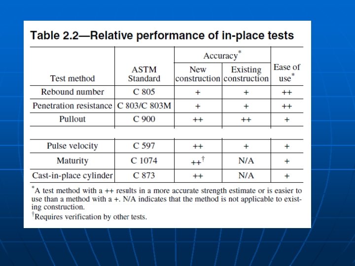
Available Testing Procedures n n n Cores Nondestructive Evaluation Load Tests
Core Strength Tests SPECIFICATIONS FOR STRUCTURAL CONCRETE ACI 301 -05 1. 6. 5. 3. a Where required by the Architect/Engineer, obtain cores in accordance with ASTM C 42/C 42 M. 1. 6. 7. 3 Core tests—Strength level of concrete in the area represented by core tests will be considered adequate when the average compressive strength of the cores is equal to at least 85% of fc′ , and if no single core is less than 75% of the specified compressive strength fc′.
Nondestructive Evaluation Unanticipated testing of hardened concrete n • Rebound Hammer ASTM C 805 • Penetrating Probe ASTM C 803 • Ultrasonic Wave Velocity Through transmission testing ASTM C 597 n Impact Echo testing ASTM C 1383 n • Pullout Test ASTM C 900
Nondestructive Tests SPECIFICATIONS FOR STRUCTURAL CONCRETE ACI 301 -05 1. 6. 6. 2 Nondestructive tests—Test results will be evaluated by the Architect/Engineer and will be valid only if tests have been conducted using properly calibrated equipment in accordance with recognized standard procedures and an acceptable correlation between test results and concrete compressive strength has been established and is submitted. * * * 1. 6. 7. 2 Nondestructive tests—Nondestructive tests shall not be used as the sole basis for accepting or rejecting concrete, but may be used, when permitted, to evaluate concrete where standard molded and cured cylinders have yielded results not meeting the criteria in 1. 6. 7. 1.
Load Test Evaluation ACI 318 -08 20. 1. 3 — If the effect of the strength deficiency is not well understood or if it is not feasible to establish the required dimensions and material properties by measurement, a load test shall be required if the structure is to remain in service.
Available Nondestructive Test Methods • Rebound Hammer ASTM C 805 • Penetrating Probe ASTM C 803 • Ultrasonic Wave Velocity Through transmission testing ASTM C 597 n Impact Echo testing ASTM C 1383 n • Pullout Test ASTM C 900
Rebound Hammer ASTM C 805
Rebound Number Correlations
Penetrating Probe ASTM C 803
Penetrating Probe ASTM C 803
Penetrating Probe Correlations
Ultrasonic Wave Evaluation
Ultrasonic Pulse Velocity ASTM C 597
Ultrasonic Pulse Velocity Correlation
Impact - Echo Testing ASTM C 1383 T=Cp/2*f Cp=T*2*f
Pullout Test ASTM C 900
Pullout Test - CAPO
Pullout Test cracking patterns
Pullout Test – CAPO correlation
In-Place Methods to Estimate Concrete Strength n ACI Report 228. 1 -03 • Review of Test Methods • Statistical Characteristics of Test Results • Development of Strength Relationship • Implementation of In-Place Testing • Interpretation and Reporting of Results • In-Place Tests for Acceptance of Concrete
Construction Project Scenario § High Rise Construction – Office Tower § Concrete Placement § Columns – 7000 psi @ 28 days 60 yards § Floor slab – 3500 psi @ 28 days 240 yards
Cylinder Test Reports § 7 day strengths § § Set 1 (slab) - 2880 psi Set 2 (slab) - 2780 psi Set 3 (slab) – 2865 psi Set 4 (column) – 3580 psi
Ultrasonic Testing at 12 days age Columns Top Middle Bottom 11500 fps 12000 fps 12500 fps Slabs 12000 fps
Validity of Ultrasonic Wave Velocity § Water content of concrete can have an effect on the wave velocity. § At higher strengths the spread of wave velocity verses compressive strength is less. § The tests of vertical elements must consider the top to bottom effect. § Ultrasonic wave tests are affected by discontinuities in the concrete.
Validity of Ultrasonic Wave Velocity § Water content of concrete can have an effect on the wave velocity. § At higher strengths the spread of wave velocity verses compressive strength is less. § The tests of vertical elements must consider the top to bottom effect. § Ultrasonic wave tests are affected by discontinuities in the concrete.
Ultrasonic Pulse Velocity
Validity of Ultrasonic Wave Velocity § Water content of concrete can have an effect on the wave velocity. § At higher strengths the spread of wave velocity verses compressive strength is less. § The tests of vertical elements must consider the top to bottom effect. § Ultrasonic wave tests are affected by discontinuities in the concrete.
Ultrasonic Pulse Velocity Top to Bottom Effect When concrete is placed in a tall vertical placement such as a column or a wall; there is a difference in the concrete strengths from top to bottom with greater strengths at the bottom of the placement.
Validity of Ultrasonic Wave Velocity § Water content of concrete can have an effect on the wave velocity. § At higher strengths the spread of wave velocity verses compressive strength is less. § The tests of vertical elements must consider the top to bottom effect. § Ultrasonic wave tests are affected by discontinuities in the concrete.
Travel time of wave through concrete
Cylinder Test Reports § 7 day strengths § § Set 1 (slab) - 2880 psi Set 2 (slab) - 2780 psi Set 3 (slab) – 2865 psi Set 4 (column) – 3580 psi § 28 day strengths § § Set 1 (slab) – 4120 psi Set 2 (slab) – 4280 psi Set 3 (slab) – 3820 psi Set 4 (column) – 4480 psi
Rebound Hammer at 35 days age Columns Average Rn = 29 Range Rn 26 to 35 Slabs Average Rn = 26 Range Rn 20 to 31
Validity of Rebound Testing § Testing the hardness (stiffness) of the concrete surface and shallow depth into concrete. § Affected by: § Form material and type and smoothness § Aggregates, closeness to surface § Reinforcing steel, closeness to surface § Moisture content § Surface finish § Hammer orientation
Rebound Number Correlations
Variation of Rebound Numbers
Cylinder Test Reports § 28 day strengths § § Set 1 (slab) – 4120 psi Set 2 (slab) – 4280 psi Set 3 (slab) – 3820 psi Set 4 (column) – 4480 psi § 56 day strengths § § Set 4 (column) – 4930 psi
Coring - PROBLEMS n n Where to core? Columns have No. 8 vertical reinforcing bars at 3 inches on center. Clear distance between bars is 2 inches. ASTM C 42 – cores for load bearing elements minimum 3. 70 inch diameter. Core between bars yields 1. 75 inch diameter – less than 2 times nominal maximum aggregate size
WHAT TO DO? ? ?
Other Nondestructive Tests n Penetration Probe • Interference from rebar n Pullout Test – CAPO Problems Number of tests required and correlation to concrete strength.
Load Tests How do you load test a column? Or 15 columns?
Load Tests of Concrete n n n Usual area load of slab Pattern loading of slabs and beams Concentrated loading of beam haunch Special jacks and tension rods for punching shear around column. Cyclic load testing using closed loop controllers and hydraulic jacks.
Discussion of load tests Strength Evaluation of Existing Concrete Buildings ACI Report 437 R-03
• Redo ultrasonic tests – concrete has dried sufficiently. • Take small diameter cores where lower wave velocities are noted. • Engineers determine that 5000 psi is sufficient strength for these columns.
Questions