
Testing of the HVDC link Italy Montenegro AUTHORS
- Slides: 19
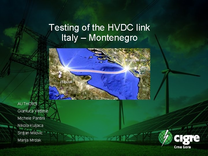
Testing of the HVDC link Italy – Montenegro AUTHORS Gianluca Vettese Michele Pantini Nikola Kuljaca Srdjan Milovic Marija Mrdak
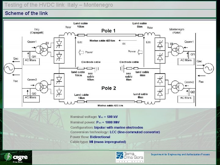
Testing of the HVDC link Italy – Montenegro Scheme of the link Stazione 1 Nominal voltage: VDC = 500 k. V Nominal power: PDC = 1000 MW Configuration: bipolar with marine electrodes Conversion technology: LCC (line-commuted converter) Power flow: Bidirectional Cable type: MI (mass impregnated) Department for Engineering and Authorization Process
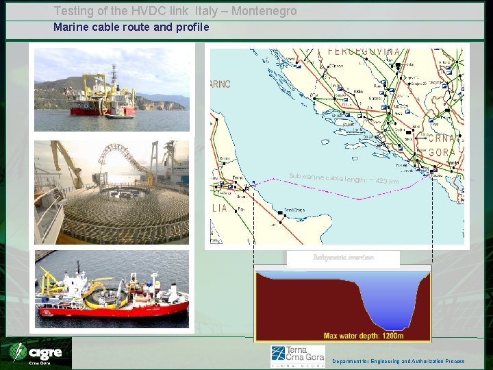
Testing of the HVDC link Italy – Montenegro Marine cable route and profile Submarine cable len gt h: ~ 423 km Bathymetric overview: Department for Engineering and Authorization Process
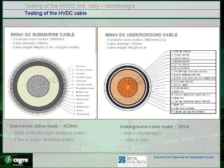
Testing of the HVDC link Italy – Montenegro Testing of the HVDC cable 500 k. V DC SUBMARINE CABLE - Conductor cross section: 1900 mm 2 - Cable diameter: 130 mm - Cable weight: 44 kg/m in air – 31 kg/m in water 500 k. V DC UNDERGROUND CABLE - Conductor cross section: 1900 mm 2 (Cu) - Cable diameter: 120 mm - Cable weight: 42 kg/m in air Submarine cable route: ~ 423 km: Underground cable route: ~ 22 km ~ 25 km in Montenegrin territorial waters ~ 6 km in Montenegro ~ 77 km in Italian territorial waters ~ 16 km in Italy Department for Engineering and Authorization Process
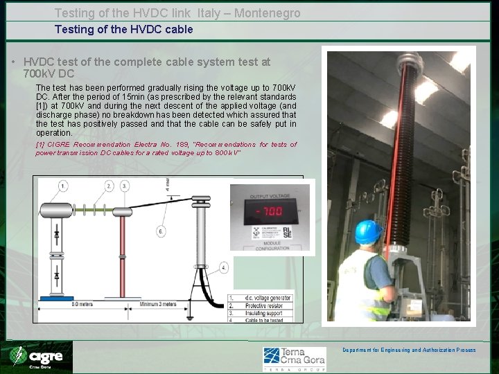
Testing of the HVDC link Italy – Montenegro Testing of the HVDC cable • HVDC test of the complete cable system test at 700 k. V DC The test has been performed gradually rising the voltage up to 700 k. V DC. After the period of 15 min (as prescribed by the relevant standards [1]) at 700 k. V and during the next descent of the applied voltage (and discharge phase) no breakdown has been detected which assured that the test has positively passed and that the cable can be safely put in operation. [1] CIGRE Recommendation Electra No. 189, “Recommendations for tests of power transmission DC cables for a rated voltage up to 800 k. V” Department for Engineering and Authorization Process
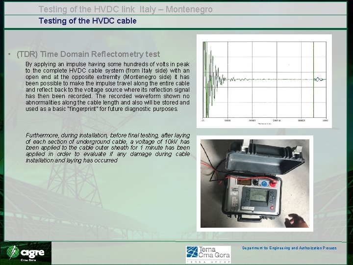
Testing of the HVDC link Italy – Montenegro Testing of the HVDC cable • (TDR) Time Domain Reflectometry test By applying an impulse having some hundreds of volts in peak to the complete HVDC cable system (from Italy side) with an open end at the opposite extremity (Montenegro side) it has been possible to make the impulse travel along the entire cable and reflect back to the voltage source where its reflection signal has then been recorded. The recorded waveform shown no abnormalities along the cable length and also will be stored and used as a basic “fingerprint” for future diagnostic purposes. Furthermore, during installation, before final testing, after laying of each section of underground cable, a voltage of 10 k. V has been applied to the cable outer sheath for 1 minute has been applied in order to evaluate if any damage during cable installation and laying has occurred Department for Engineering and Authorization Process
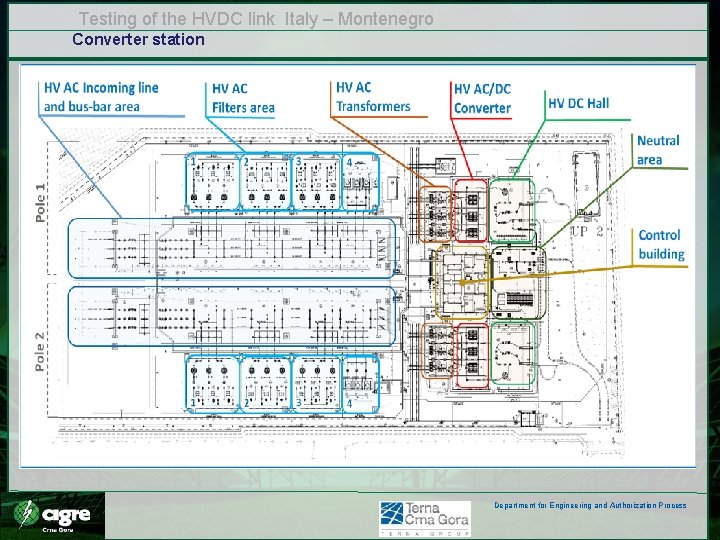
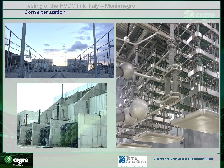
Testing of the HVDC link Italy – Montenegro Converter station Department for Engineering and Authorization Process
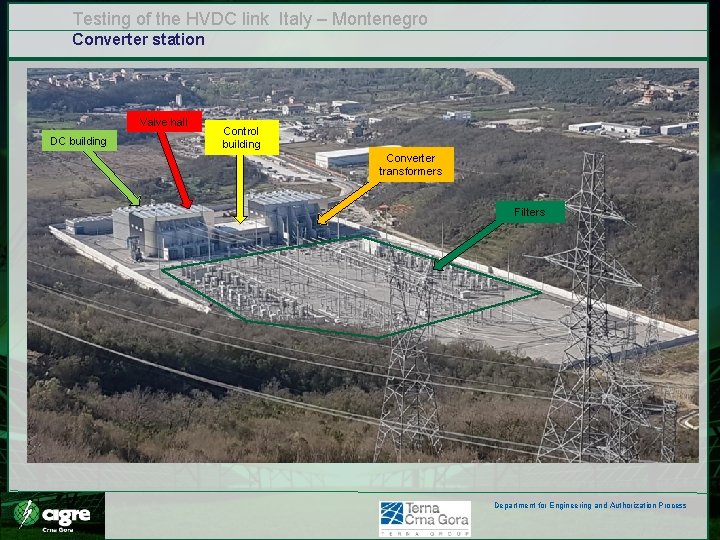
Testing of the HVDC link Italy – Montenegro Converter station Valve hall DC building Control building Converter transformers Filters Department for Engineering and Authorization Process
Testing of the HVDC link Italy – Montenegro Converter station Department for Engineering and Authorization Process
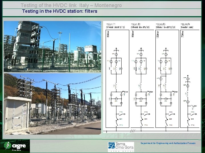
Testing of the HVDC link Italy – Montenegro Testing in the HVDC station: filters Department for Engineering and Authorization Process
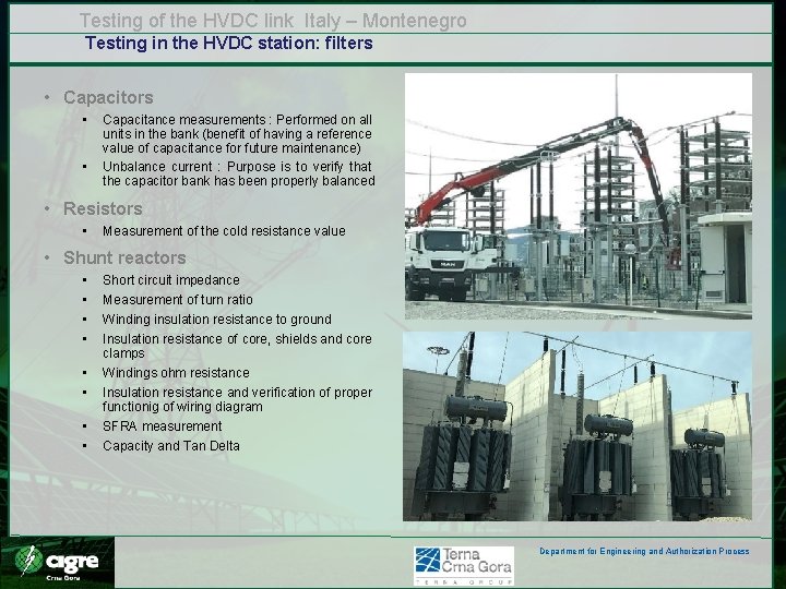
Testing of the HVDC link Italy – Montenegro Testing in the HVDC station: filters • Capacitors • • Capacitance measurements : Performed on all units in the bank (benefit of having a reference value of capacitance for future maintenance) Unbalance current : Purpose is to verify that the capacitor bank has been properly balanced • Resistors • Measurement of the cold resistance value • Shunt reactors • • Short circuit impedance Measurement of turn ratio Winding insulation resistance to ground Insulation resistance of core, shields and core clamps Windings ohm resistance Insulation resistance and verification of proper functionig of wiring diagram SFRA measurement Capacity and Tan Delta Department for Engineering and Authorization Process
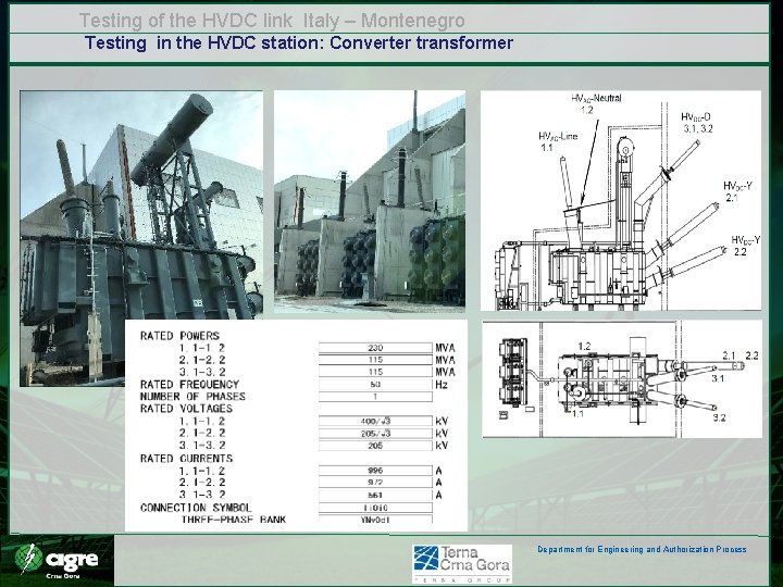
Testing of the HVDC link Italy – Montenegro Testing in the HVDC station: Converter transformer Department for Engineering and Authorization Process
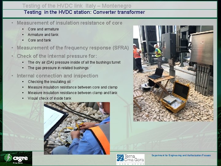
Testing of the HVDC link Italy – Montenegro Testing in the HVDC station: Converter transformer • Measurement of insulation resistance of core • • • Core and armature Armature and tank Core and tank • Measurement of the frequency response (SFRA) • Check of the internal pressure for: • • The dry air (DA) pressure inside of all the bushings turret The gas pressure in related bushings • Internal connection and inspection • • Checking the insulating oil Measure insulation resistance between core and clamp Measure insulation resistance between clamp and tank Visual check of inside tank Department for Engineering and Authorization Process
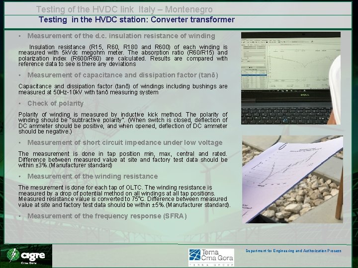
Testing of the HVDC link Italy – Montenegro Testing in the HVDC station: Converter transformer • Measurement of the d. c. insulation resistance of winding Insulation resistance (R 15, R 60, R 180 and R 600) of each winding is measured with 5 k. Vdc megohm meter. The absorption ratio (R 60/R 15) and polarization index (R 600/R 60) are calculated. Results are compared with reference data to see is there any deviations • Measurement of capacitance and dissipation factor (tanδ) Capacitance and dissipation factor (tanδ) of windings including bushings are measured at 50 Hz-10 k. V with tanδ measuring system • Check of polarity Polarity of winding is measured by inductive kick method. The polarity of winding should be “subtractive polarity”. (When switch is closed, deflection of DC ammeter should be positive, and when opened, deflection of DC ammeter should be negative. ) • Measurement of short circuit impedance under low voltage The measurement is done in tap position min, max, central and rated. Difference between measured value at site and factory test data should be within ± 3%. (Manufacturer standard) • Measurement of the winding resistance The mesurement is done for each tap of OLTC. The winding resistance is measured by a drop of potential method on all windings at all tap positions. Measured resistance value is converted to 75℃. Difference between measured value at site and factory test data should be within ± 5%. (Manufacturer standard). • Measurement of the frequency response (SFRA) Department for Engineering and Authorization Process
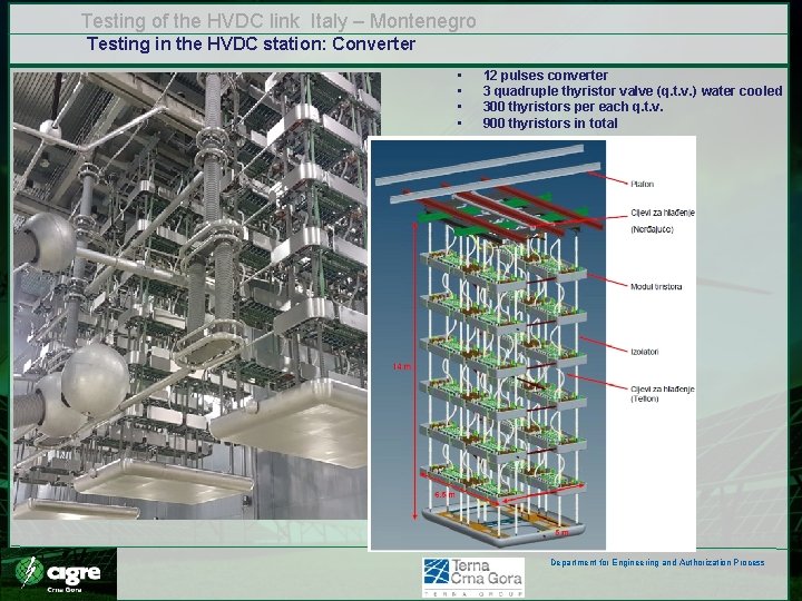
Testing of the HVDC link Italy – Montenegro Testing in the HVDC station: Converter • • 12 pulses converter 3 quadruple thyristor valve (q. t. v. ) water cooled 300 thyristors per each q. t. v. 900 thyristors in total Department for Engineering and Authorization Process
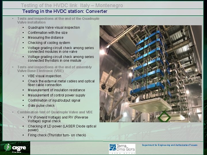
Testing of the HVDC link Italy – Montenegro Testing in the HVDC station: Converter • Tests and inspections at the end of the Quadruple Valve installation • Quadruple Valve visual inspection • Confirmation with the size • Measuring the distance • Checking of cooling system • Voltage grading circuit check among series connected modules in one valve • Voltage grading circuit check among series connected thyristors in one module • Tests and inspections at the end of assembly Valve Base Electronic (VBE) • VBE visual inspection • Check the external metal cables and optical fiber cable connection • Measurement of insulation resistance • Measurement of control power supply • Confirmation of input/output signal • Gate pulse check • Combination test of Quadruple Valve and VBE • FV (Forward Voltage) and RV (Reverse Voltage) signal check • Checking of LD power (LASER Diode optical power) • Firing check (Thyristor turn- on check) Department for Engineering and Authorization Process
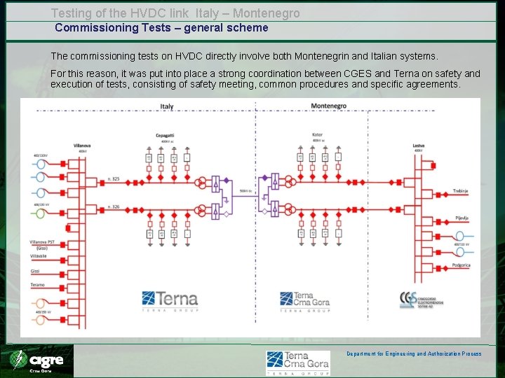
Testing of the HVDC link Italy – Montenegro Commissioning Tests – general scheme The commissioning tests on HVDC directly involve both Montenegrin and Italian systems. For this reason, it was put into place a strong coordination between CGES and Terna on safety and execution of tests, consisting of safety meeting, common procedures and specific agreements. Department for Engineering and Authorization Process
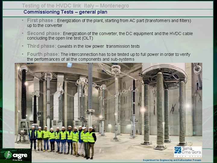
Testing of the HVDC link Italy – Montenegro Commissioning Tests – general plan • First phase : Energization of the plant, starting from AC part (transformers and filters) up to the converter • Second phase: Energization of the converter, the DC equipment and the HVDC cable concluding the open line test (OLT) • Third phase: Consists in the low power transmission tests • Fourth phase: The interconnection has to be tested up to full power in order to verify the performances of all the components and sub-systems Department for Engineering and Authorization Process
THANK YOU FOR YOUR ATTENTION