TENSION MEMBERS PREPARED BY SHAMILAH ANUDAIANUAR INTRODUCTION Tension

TENSION MEMBERS PREPARED BY SHAMILAH ANUDAI@ANUAR

INTRODUCTION Tension members are structural element that are subjected to axial tensile forces. Example : → trusses members → Cable system in cable-stayed or suspension bridges →Bracing in frames system → transmission or communication towers
 Single structural shapes")
Types of Tension Members Consist of two main shapes : A) Single structural shapes such as angle section, channel section, I-section, Tee section, Box section and Tubular section - More economical - Generally used in tower and trusses
 Double angle members - More rigid as compared with single angle members -")
B) Double angle members - More rigid as compared with single angle members - Generally used in roof trusses - Eg : built up channel, built up I-section - Generally interconnected at regular intervals and act as one integral members
 WT shape (Tee) Double angle Circular rod Double channel")
Steel Sections L shape (angle) WT shape (Tee) Double angle Circular rod Double channel Circular rod Built up plate and angle shape (double plane truss)

The application of Tension Members

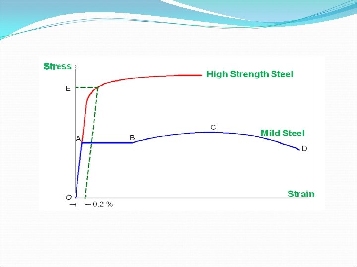
Behavior of Tension Members • The upper yield point is merged with the lower yield point for convenience. • The material shows a linear elastic behavior in the initial region (O to A). • The material undergoes sufficient yielding in portion A to B. • Further deformation leads to an increase in resistance, where the material strain hardens (from B to C) • The material reaches its ultimate stress at point C. • The stress decreases with increase in further deformation and breaks at D.

Modes of failure of tension members Gross section yielding Net section rupture Block shear failure

Failure occurs by rupture on the shear area and rupture on the tension area Both surface (shear and tension) contribute to total strength

Design Strength of Tension Members Nominal Strength - The strength of a tension member may be described in terms of the “limit states” that govern - The controlling strength limit state for a tension member can either : a) Yielding of the gross-section of the member away from the connection or b) Fracture of the effective net area (i. e: through the holes) at the connection
 - When the")
Design Strength of Tension Members Load and Resistance Factor Design (LRFD) - When the limit state is general yielding of the gross section over the member length, as for a tension member without holes (i. e. , with welded connection), the nominal strength Pn is expressed as : - Where;
 - For tension members having holes, such as for rivet")
LFRD Specification (cont’d) - For tension members having holes, such as for rivet or bolts, the reduced cross section is referred as the net area. - Holes in member cause stress concentration (nonuniform stresses) - For example, a hole in a plate with a tensile service force P produces a stress distribution at service load as shown in Figure below Elastic stress distribution with holes present
 - Theory of elasticity shows that tensile stress adjacent to")
LRFD Specification (cont’d) - Theory of elasticity shows that tensile stress adjacent to the hole will about three times the average stress on the net area - However, as each fiber reaches yield strain, that is its stress then becomes a constant with deformation continuing with increasing load until finally all fibers have achieved or exceeded the strain Ultimate condition – Stress distribution with holes present
 - When the limit state is a localized yielding resulting")
LRFD Specification (cont’d) - When the limit state is a localized yielding resulting in a fracture through the effective net area of a tension member having holes, the nominal strength Pn is expressed as : Where;

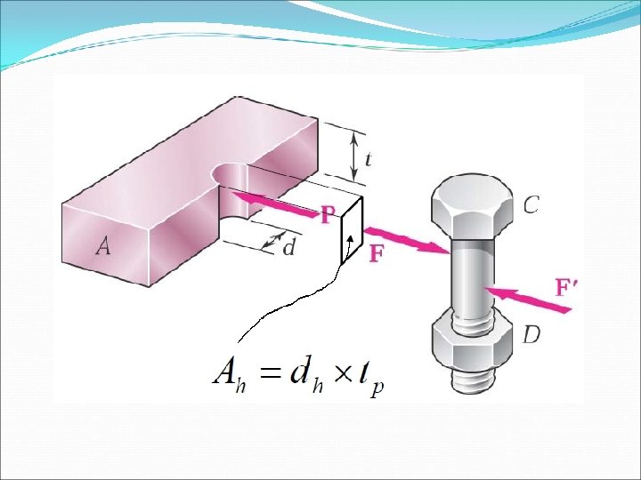
Net Area, An - Whenever a tension member is to be fastened by means of bolts or rivets, holes must be provided at the connection - Therefore, the member cross sectional area is reduced and the strength of the member may also be reduced depending on the size and location of the holes - The term “ net cross-sectional area “ or “ net area “ refers to the gross sectional area of the member minus the holes, notches or other indentations
 - Method for cutting holes 1. The most common and")
Net Areas (An) - Method for cutting holes 1. The most common and least expensive method is to punch standard holes 1/16 in (1. 6 mm) larger than the diameter of the rivet or bolt. In general, the plate thickness is less than the punch diameter. This is accounted in design by assuming that the extend of the damage is limited to a radial distance of 1/32 in (0. 8 mm) around the hole.
 2. A second of cutting holes consists of sub-p unching")
Net Areas, An (cont’d) 2. A second of cutting holes consists of sub-p unching them 3/16 in (4. 8 mm) diameter undersize and them reaming the holes to the finished size after the pieces being joined are assembled This method is more expensive, but offers the advantage of accurate alignment. This method produces better strength.
 3. A third method consists of drilling holes to a")
Net Areas, An (cont’d) 3. A third method consists of drilling holes to a diameter of the rivet or bolt plus 1/32 in (0. 8 mm) This method is used to join thick pieces and is the most expensive of the all common methods.

Hole Area calculation The area of the hole is considered a rectangular area and is computed as follows : For fastener in standard holes;

Example 1 Find the net Area An for the tension member shown in Figure below :

Example 2 Determine the net area of the 3/8 x 8 in plate shown below. The plate is connected at its ends with two lines ¾ in bolts

Example 3 Compute the net area An for the member shown in the figure below. Using a WT 12 x 31, the following properties can be obtained from the AISC steel manual
, in an")
Members subjected to axial tension only The applied tensile stress (σt. a), in an axially loaded timber member is calculated from the following equation: Where : T = tensile force Anet = net cross-sectional area The permissible tensile stress (σt. adm), is calculate as the product of the grade tensile stress, (σt. g) and any relevant modification factors (K-factors) as follows : Where K is general modification factors load-duration and load sharing systems

However, the value of applied tensile stress, should not exceed the permissible tensile stress, hence :

Combined bending and tensile stresses In members that are subjected to lateral loading as well as the axial tension, the positions of maximum stress occurs at the point of maximum bending moment. Sum of the ratios of the applied tensile and bending stress to those of the permissible ones (i. e. interaction quantity) must not exceed unity : Where : Applied tensile stress, Permissible tensile stress, Applied bending stress, Permissible bending stress,

EXAMPLE A trussed rafter tie of 38 mm x 100 mm section is 2. 7 m long and is subjected to a lateral concentrated load of 0. 65 k. N at mid-length. Determine the maximum medium term axial tensile load that the rafter tie can carry. Assume a timber in strength class SG 3. 0. 65 k. N T T 0. 325 k. N L = 2. 7 m

THANK YOU VERY MUCH FOR YOUR ATTENTION
- Slides: 29