
TELEVISION VIDEO ENGINEERING BY S R GANAR Persistence
TELEVISION & VIDEO ENGINEERING BY S. R. GANAR
Persistence of vision: the eye (or the brain rather) can retain the sensation of an image for a short time even after the actual image is removed. Frame merging This allows the display of a video as successive frames as long as the frame interval is shorter than the persistence period, The eye will see a continuously varying image in time.
When the frame interval is too long, the eye observes frame flicker. The minimal frame rate (frames/ second or fps or Hz) required to prevent frame flicker depends on display brightness, viewing distance. Higher frame rate is required with closer viewing and brighter display. For TV viewing: 50 - 60 fps For Movie viewing: 24 fps For computer monitor: > 70 fps
Line merging As with frame merging, the eye can fuse separate lines into one complete frame, as long as the spacing between lines is sufficiently small. The maximum vertical spacing between lines depends on the viewing distance, the screen size, and the display brightness. For common viewing distance and TV screen size, 500 - 600 lines per frame is acceptable
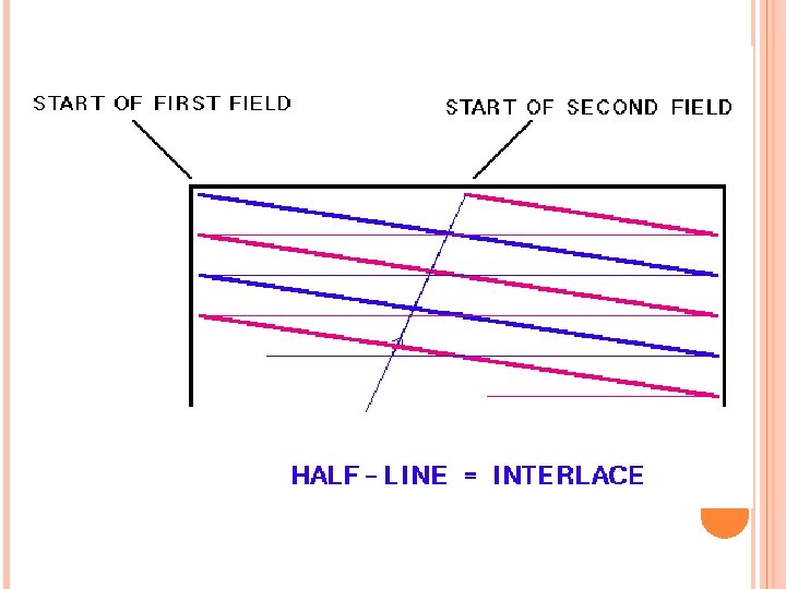
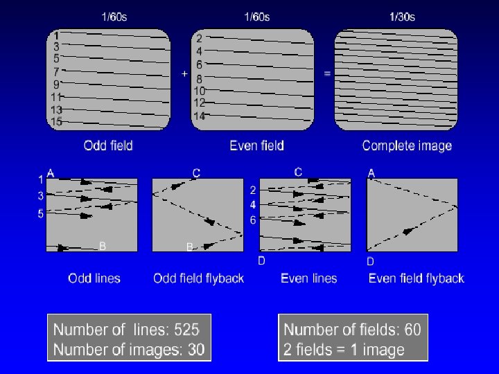
Interlacing For some reason, the brighter the still image presented to the viewer. . . the shorter the persistence of vision. If the space between pictures is longer than the period of persistence of vision the image flickers. Therefore, to arrange for two "flashes" per frame, interlacing creates the flashes. The basic idea here is that a single frame is scanned twice. The first scan includes only the odd lines, the next scan includes only the even lines.
Basic black and white television In a basic black and white TV, a single electron beam is used to scan a phosphor screen. The scan is interlaced, that is -- it scans twice per photographed frame. The information is always displayed from left to right. After each line is written, when the beam returns back to the left, the signal is blanked. When the signal reached the bottom it is blanked until it returns to the top to write the next line
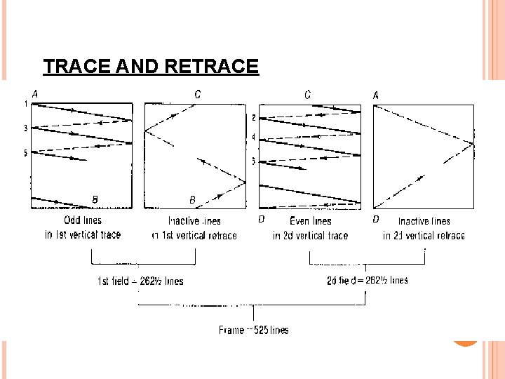
TRACE AND RETRACE
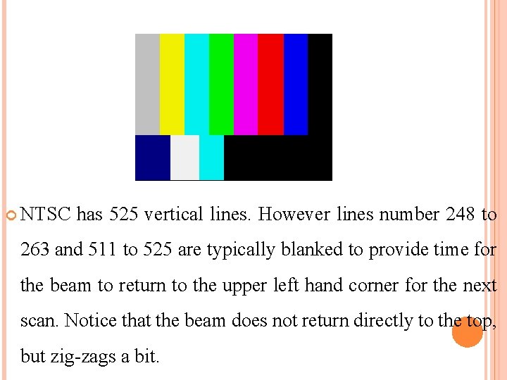
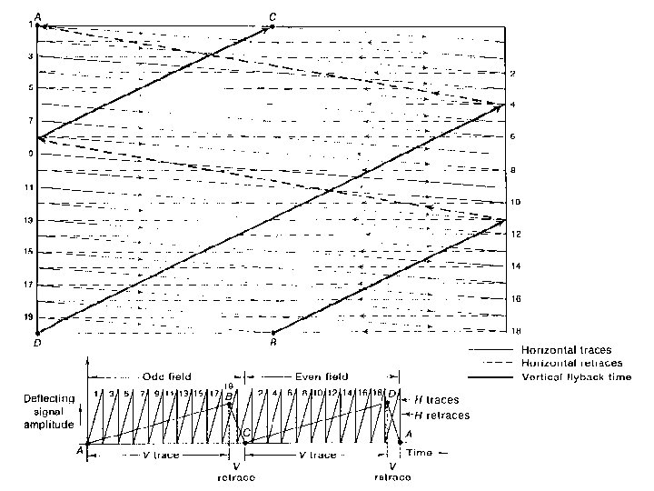
NTSC has 525 vertical lines. However lines number 248 to 263 and 511 to 525 are typically blanked to provide time for the beam to return to the upper left hand corner for the next scan. Notice that the beam does not return directly to the top, but zig-zags a bit.
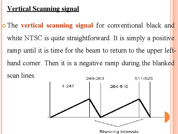
Vertical Scanning signal The vertical scanning signal for conventional black and white NTSC is quite straightforward. It is simply a positive ramp until it is time for the beam to return to the upper lefthand corner. Then it is a negative ramp during the blanked scan lines.
Horizontal Scan signal The horizontal scan signal is very much the same. The horizontal scan rate is 525*29. 97 or 15, 734 Hz. Therefore, 63. 6 u. S are allocated per line. Typically about 10 u. S of this is devoted to the blanking line on the horizontal scan. There are 427 pixels per horizontal scan line and so each pixel is scanned for approximately 125 ns.
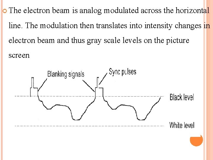
The electron beam is analog modulated across the horizontal line. The modulation then translates into intensity changes in electron beam and thus gray scale levels on the picture screen
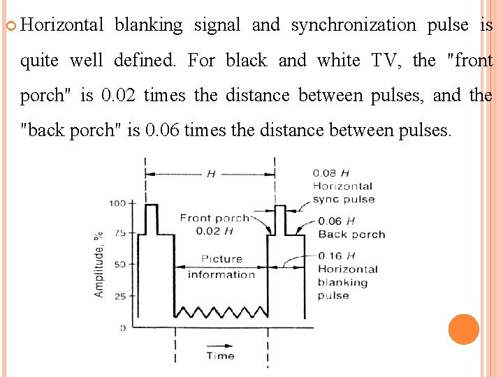
Horizontal blanking signal and synchronization pulse is quite well defined. For black and white TV, the "front porch" is 0. 02 times the distance between pulses, and the "back porch" is 0. 06 times the distance between pulses.
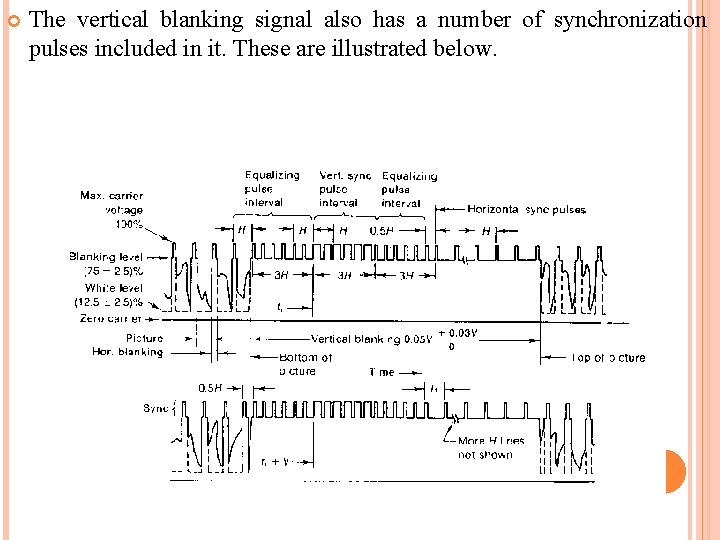
The vertical blanking signal also has a number of synchronization pulses included in it. These are illustrated below.
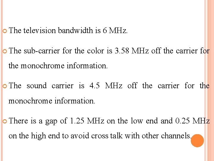
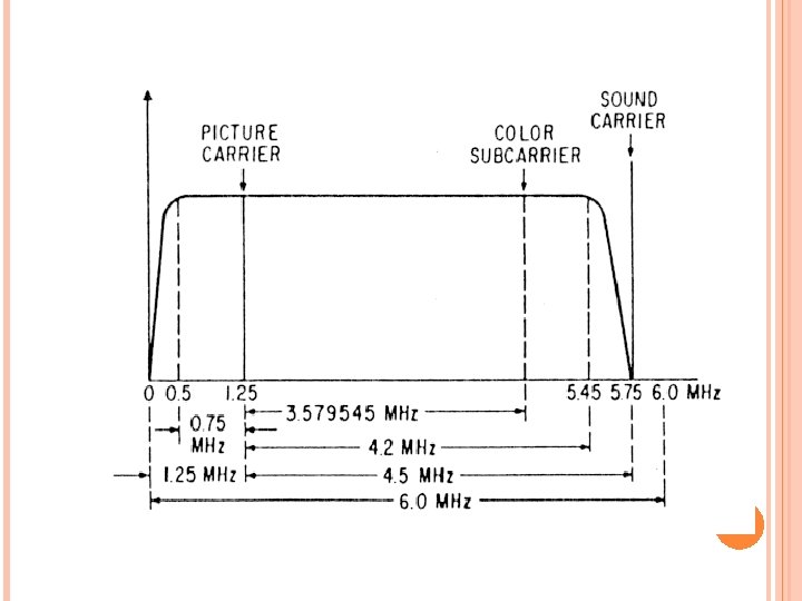
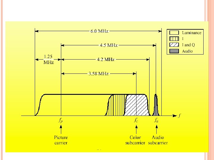
The television bandwidth is 6 MHz. The sub-carrier for the color is 3. 58 MHz off the carrier for the monochrome information. The sound carrier is 4. 5 MHz off the carrier for the monochrome information. There is a gap of 1. 25 MHz on the low end and 0. 25 MHz on the high end to avoid cross talk with other channels.
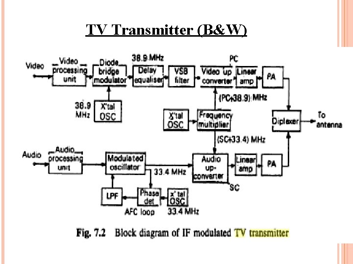
TV Transmitter (B&W)
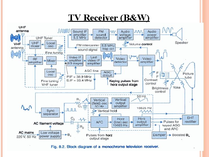
TV Receiver (B&W)
COLOR TELEVISION One of the great electrical engineering triumphs was the development of color television in such a way that it remained compatible with black and white television. A major driving force behind the majority of current color TV standards was to allow black-and-white TVs to continue to be able to receive a valid TV signal after color service was in place.
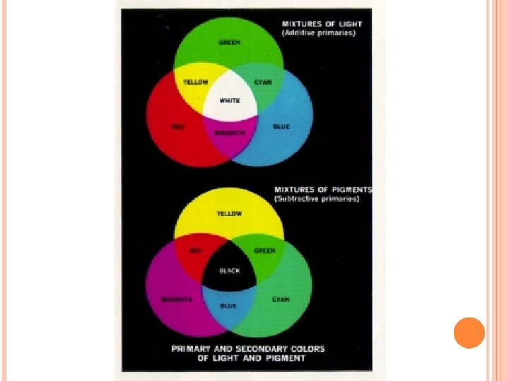
Trireceptor theory of vision why we use RGB monitors If you ask someone why red, green and blue are used in computer monitors -- the immediate answer is "Because these are the primary colors". If you then ask, "But why are these the primary colors? " -- the answer you get is that "If you mix light of these colors together you can make any color".
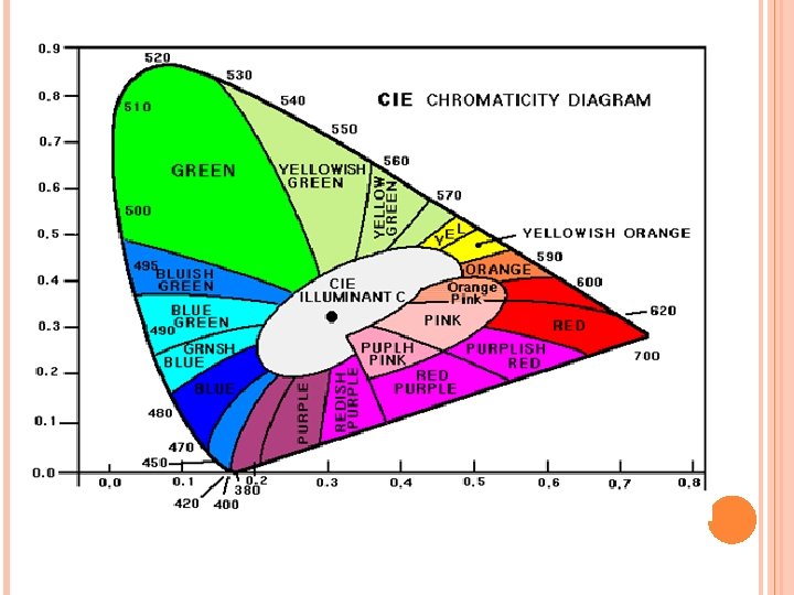
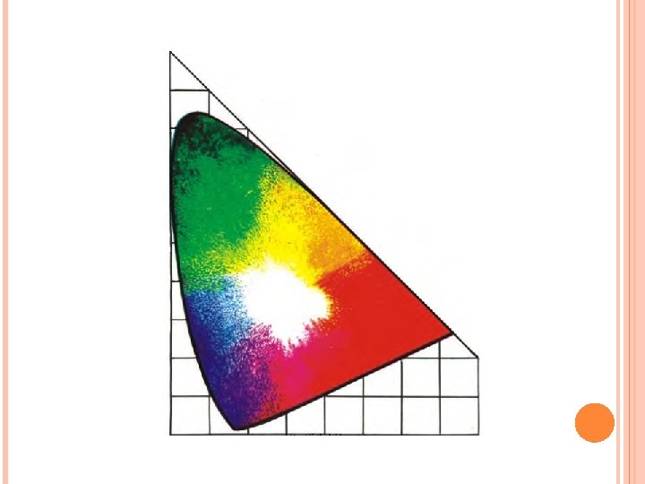
Color information transmission in TV In the most basic form, color television could simply be implemented by having cameras with three filters (red, green and blue) and then transmitting the three color signals over wires to a receiver with three electron guns and three drive circuits. Unfortunately, this idealized view is not compatible with the previously allocated 7 MHz bandwidth of a TV channel. It is also not compatible with previously existing monochrome receivers.
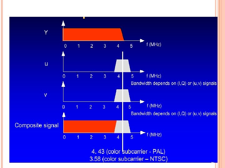
Therefore, modern color TV is carefully structured to preserve all the original monochrome information -- and just add on the color information on top. To do this, one signal, called luminance (Y) has been chosen to occupy the major portion (0 -4 MHz) of the channel. Y contains the brightness information and the detail. Y is the monochrome TV signal. Consider the model of a scene being filmed with three cameras. One camera has a red filter, one camera a green filter and one camera a blue filter.
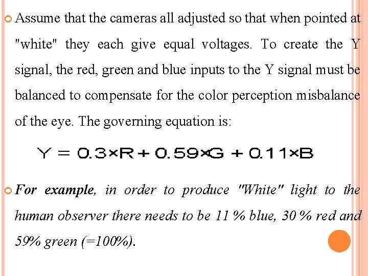
Assume that the cameras all adjusted so that when pointed at "white" they each give equal voltages. To create the Y signal, the red, green and blue inputs to the Y signal must be balanced to compensate for the color perception misbalance of the eye. The governing equation is: For example, in order to produce "White" light to the human observer there needs to be 11 % blue, 30 % red and 59% green (=100%).
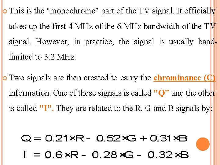
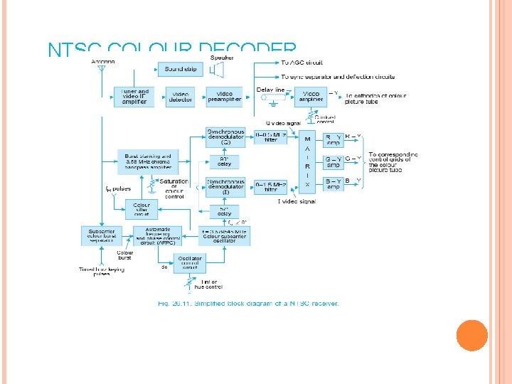
This is the "monochrome" part of the TV signal. It officially takes up the first 4 MHz of the 6 MHz bandwidth of the TV signal. However, in practice, the signal is usually bandlimited to 3. 2 MHz. Two signals are then created to carry the chrominance (C) information. One of these signals is called "Q" and the other is called "I". They are related to the R, G and B signals by:
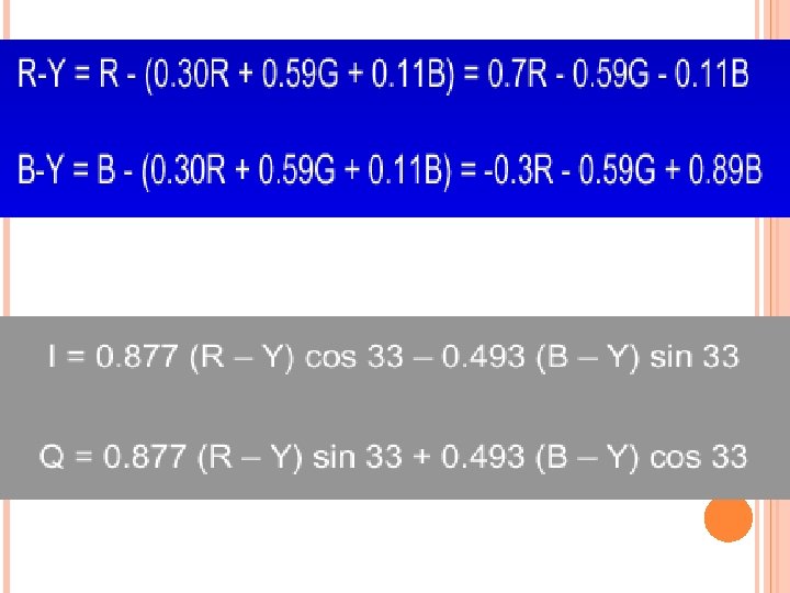
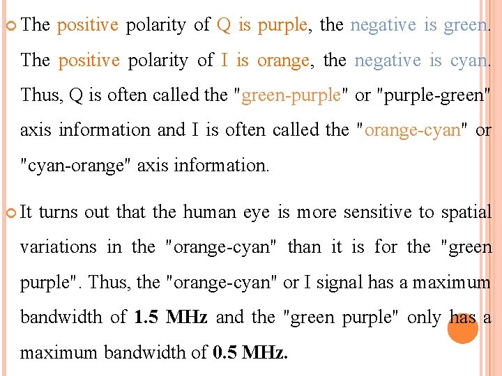
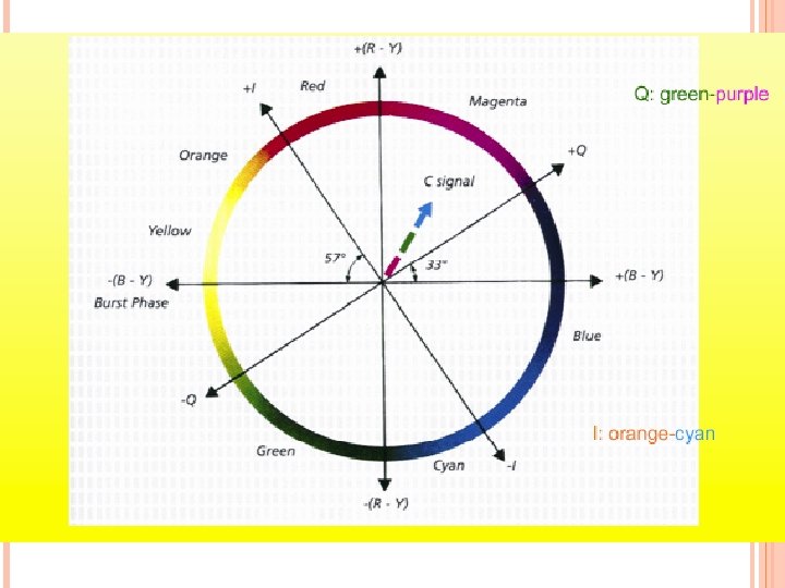
The positive polarity of Q is purple, the negative is green. The positive polarity of I is orange, the negative is cyan. Thus, Q is often called the "green-purple" or "purple-green" axis information and I is often called the "orange-cyan" or "cyan-orange" axis information. It turns out that the human eye is more sensitive to spatial variations in the "orange-cyan" than it is for the "green purple". Thus, the "orange-cyan" or I signal has a maximum bandwidth of 1. 5 MHz and the "green purple" only has a maximum bandwidth of 0. 5 MHz.
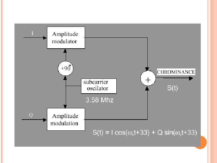
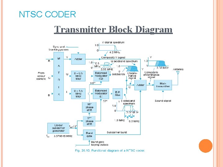
Now, the Q and I signals are both modulated by a 3. 58 MHz carrier wave. However, they are modulated out of 90 degrees out of phase. (QAM) These two signals are then summed together to make the C or chrominance signal. The nomenclature of the two signals aids in remembering what is going on. The I signal is In-phase with the 3. 58 MHz carrier wave. The Q signal is in Quadrature (i. e. 1/4 of the way around the circle or 90 degrees out of phase, or orthogonal) with the 3. 58 MHz carrier wave.
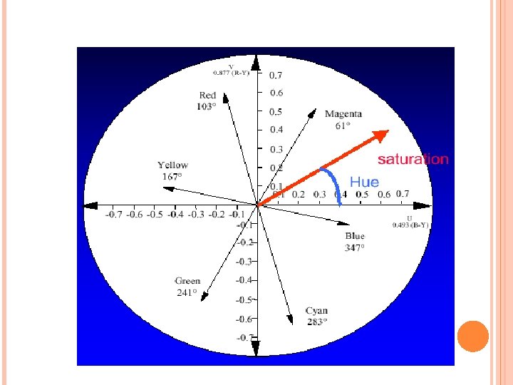
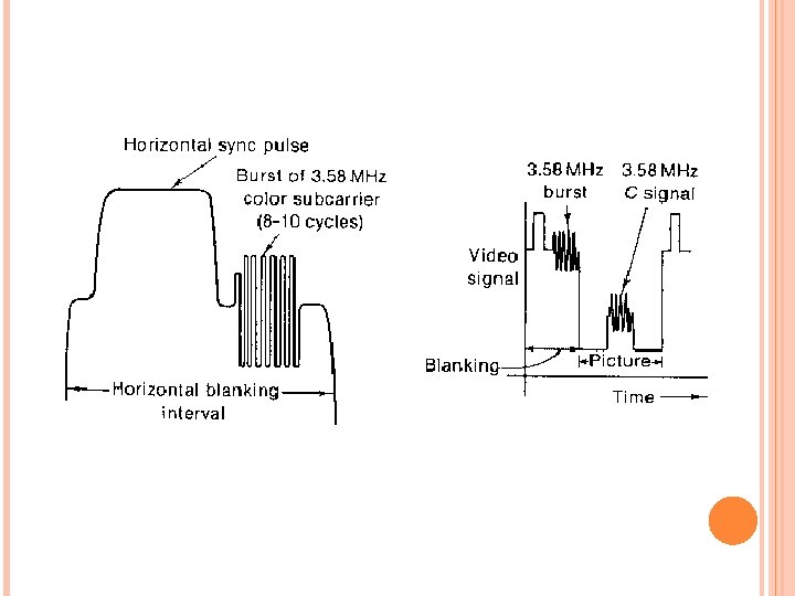
New chrominance signal (formed by Q and I) has the interesting property that the magnitude of the signal represents the color saturation, and the phase of the signal represents the hue. Phase = Arctan (Q/ I) = hue Magnitude = sqrt (I 2+ Q 2) = saturation Now, since the I and Q signals are clearly phase sensitive -- some sort of phase reference must be supplied. This reference is supplied after each horizontal scan and is included on the "back porch" of the horizontal sync pulse. The phase reference consists of 8 -10 cycles of the 3. 58 MHz signal. It is called the "color burst" and looks something like this
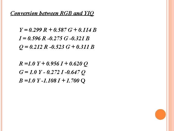
Conversion between RGB and YIQ Y = 0. 299 R + 0. 587 G + 0. 114 B I = 0. 596 R -0. 275 G -0. 321 B Q = 0. 212 R -0. 523 G + 0. 311 B R =1. 0 Y + 0. 956 I + 0. 620 Q G = 1. 0 Y - 0. 272 I -0. 647 Q B =1. 0 Y -1. 108 I + 1. 700 Q
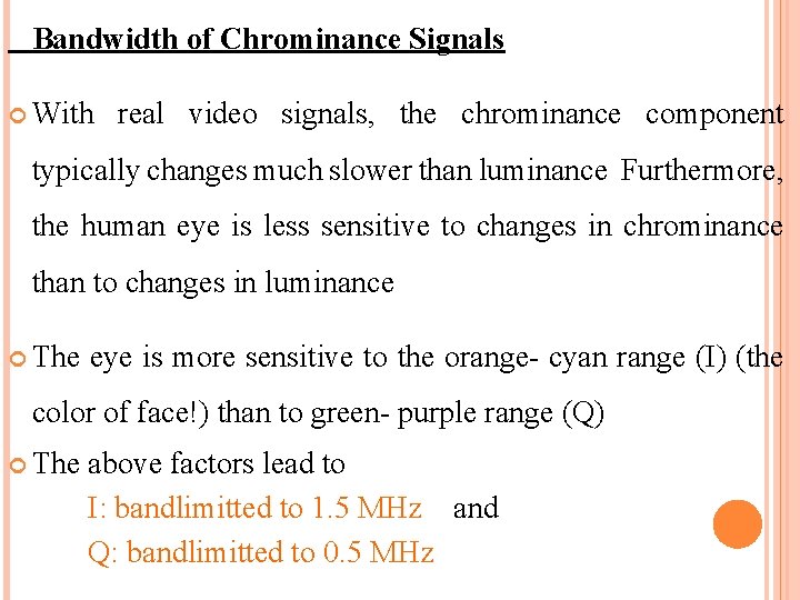
Bandwidth of Chrominance Signals With real video signals, the chrominance component typically changes much slower than luminance Furthermore, the human eye is less sensitive to changes in chrominance than to changes in luminance The eye is more sensitive to the orange- cyan range (I) (the color of face!) than to green- purple range (Q) The above factors lead to I: bandlimitted to 1. 5 MHz and Q: bandlimitted to 0. 5 MHz
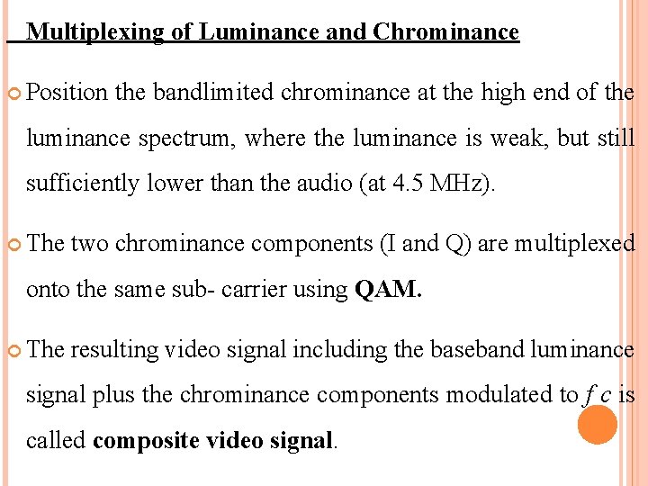
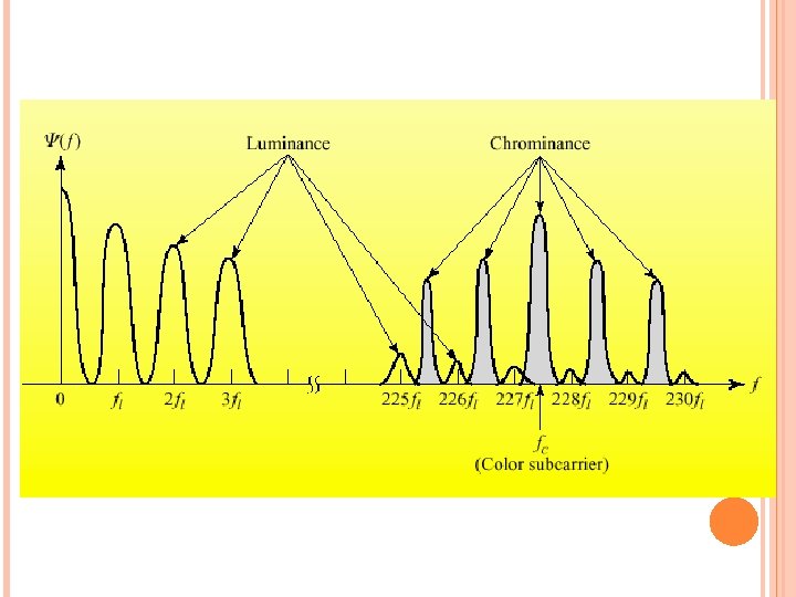
Multiplexing of Luminance and Chrominance Position the bandlimited chrominance at the high end of the luminance spectrum, where the luminance is weak, but still sufficiently lower than the audio (at 4. 5 MHz). The two chrominance components (I and Q) are multiplexed onto the same sub- carrier using QAM. The resulting video signal including the baseband luminance signal plus the chrominance components modulated to f c is called composite video signal.
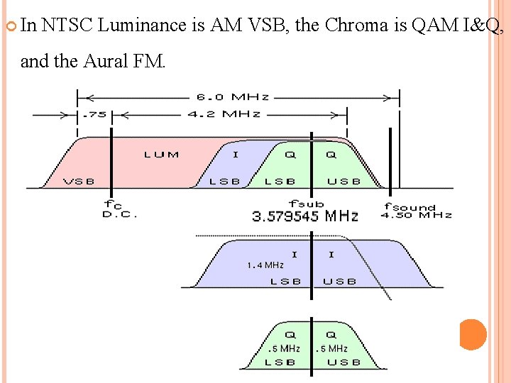
In NTSC Luminance is AM VSB, the Chroma is QAM I&Q, and the Aural FM.
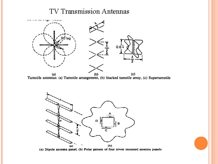
TV Transmission Antennas
NTSC CODER Transmitter Block Diagram
NTSC COLOUR DECODER
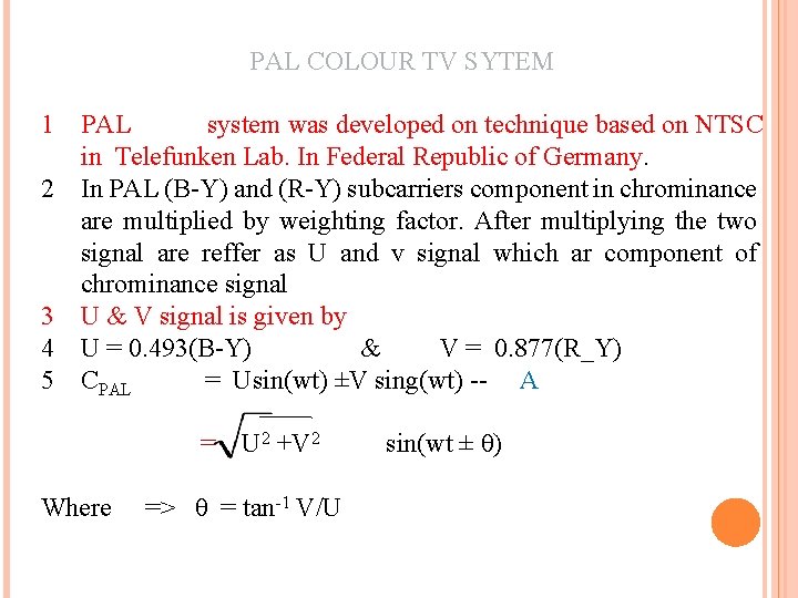
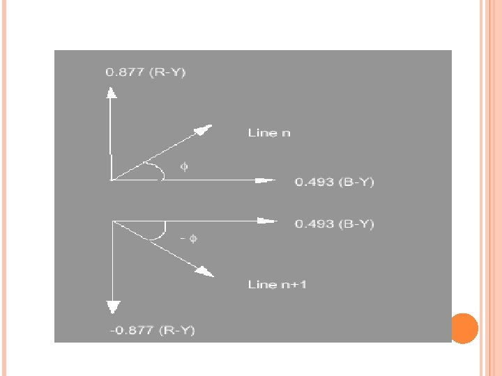
PAL COLOUR TV SYTEM 1 PAL system was developed on technique based on NTSC in Telefunken Lab. In Federal Republic of Germany. 2 In PAL (B-Y) and (R-Y) subcarriers component in chrominance are multiplied by weighting factor. After multiplying the two signal are reffer as U and v signal which ar component of chrominance signal 3 U & V signal is given by 4 U = 0. 493(B-Y) & V = 0. 877(R_Y) 5 CPAL = Usin(wt) ±V sing(wt) -- A = Where U 2 +V 2 => θ = tan-1 V/U sin(wt ± θ)
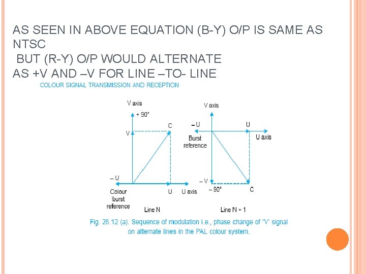
AS SEEN IN ABOVE EQUATION (B-Y) O/P IS SAME AS NTSC BUT (R-Y) O/P WOULD ALTERNATE AS +V AND –V FOR LINE –TO- LINE
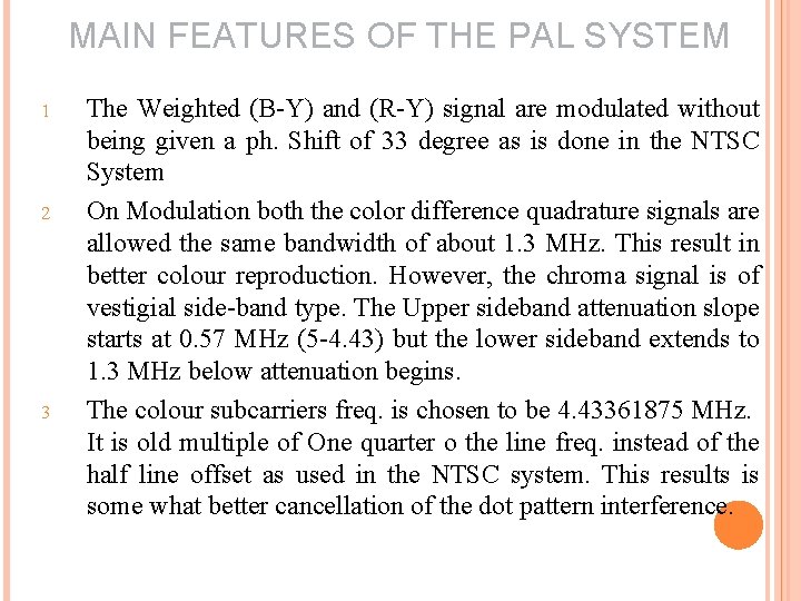
MAIN FEATURES OF THE PAL SYSTEM 1 2 3 The Weighted (B-Y) and (R-Y) signal are modulated without being given a ph. Shift of 33 degree as is done in the NTSC System On Modulation both the color difference quadrature signals are allowed the same bandwidth of about 1. 3 MHz. This result in better colour reproduction. However, the chroma signal is of vestigial side-band type. The Upper sideband attenuation slope starts at 0. 57 MHz (5 -4. 43) but the lower sideband extends to 1. 3 MHz below attenuation begins. The colour subcarriers freq. is chosen to be 4. 43361875 MHz. It is old multiple of One quarter o the line freq. instead of the half line offset as used in the NTSC system. This results is some what better cancellation of the dot pattern interference.
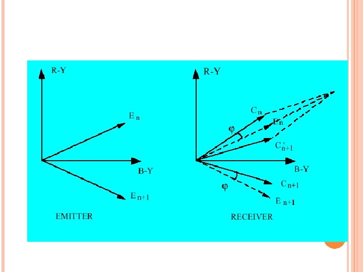
MAIN FEATURES OF THE PAL SYSTEM. . Continued 4 The weihted (B-Y) and (R-Y) signals are modulated with the subcarrier in the same way as in the NTSC sytem(QAM) but with the difference that ph. of the subcarrier to one of the modulators ( V modulator) is is reverse form +900 to -900 In fact the system derivers its name Ph. Alteration by line (PAL) for this modulation. This technique of modulation cancels hue errors which results from unequal ph. Shift in the transmitted signal.
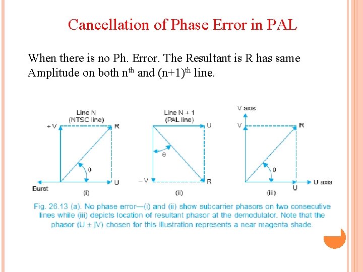
Cancellation of Phase Error in PAL When there is no Ph. Error. The Resultant is R has same Amplitude on both nth and (n+1)th line.
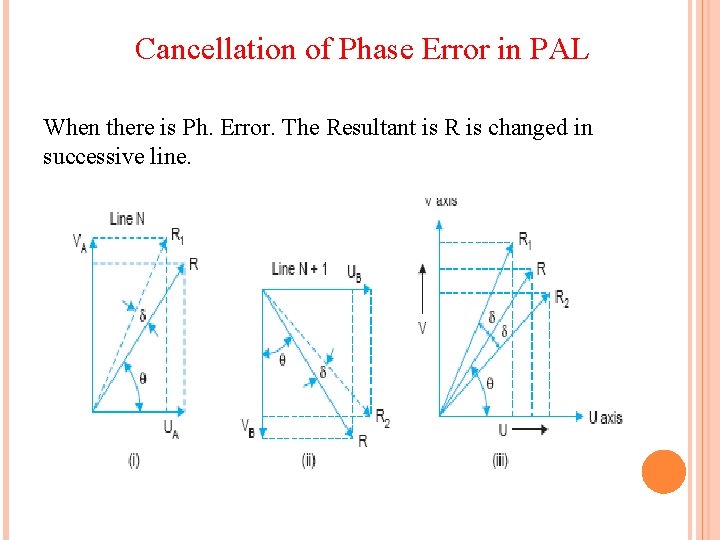
Cancellation of Phase Error in PAL When there is Ph. Error. The Resultant is R is changed in successive line.
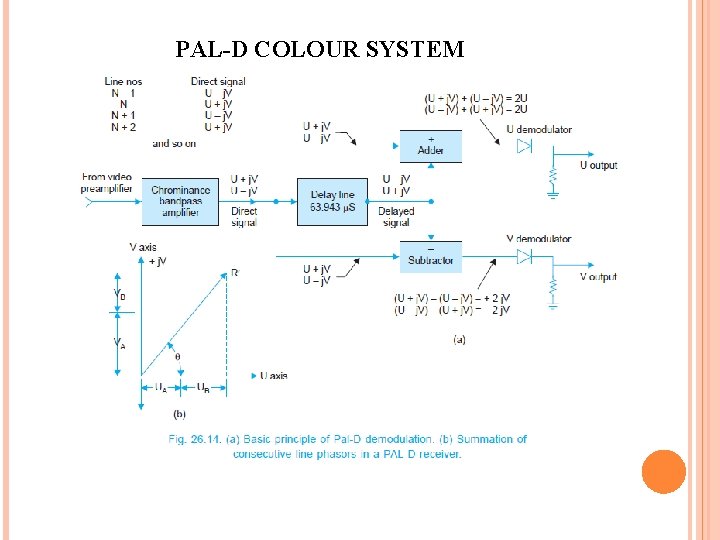
PAL-D COLOUR SYSTEM
• To permit precise addition and subtraction of direct and delayed line signals, the delay line must introduce a delay which is equivalent to the duration of an exact number of half cycles of the chrominance signal • This requirement would not be met if the line introduced a • . delay of exactly 64 μs • At a frequency of 4. 43361875 MHz the number of cycles which take place in 64 μs are 4. 43361875 × 106 × 64 × 10– 6 = 283. 7485998 Hz, ≈ 283. 75 Hz. A delay line which introduces a delay equal to the duration of 283. 5 subcarrier cycles is therefore suitable is equal to a time delay of 63. 943 μs (1/fsc × 283. 5).
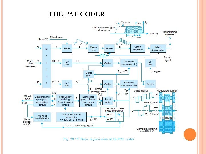
THE PAL CODER
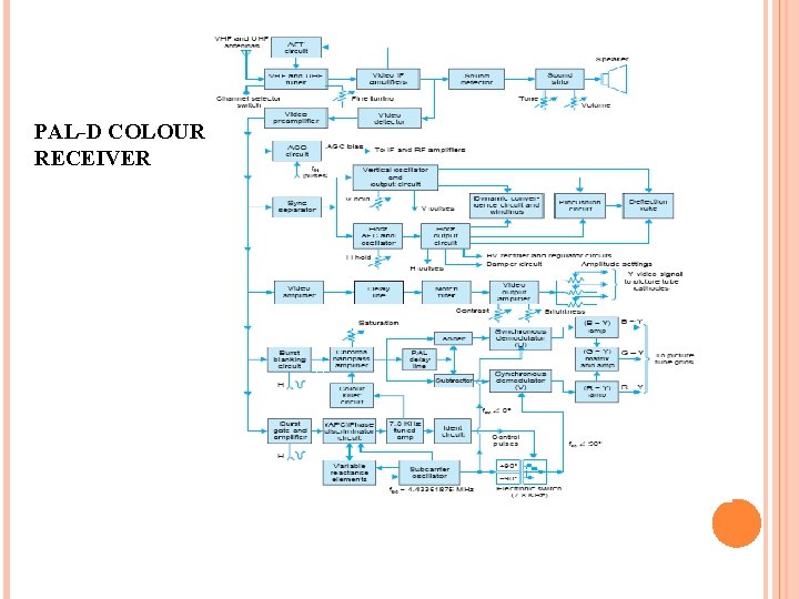
PAL-D COLOUR RECEIVER
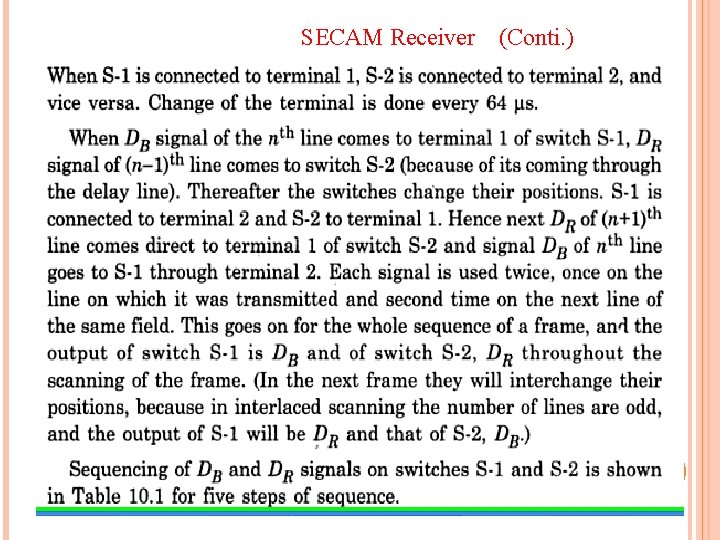
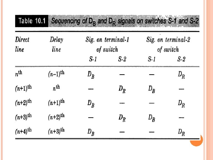
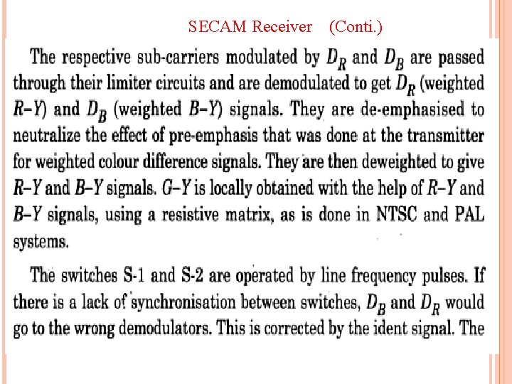
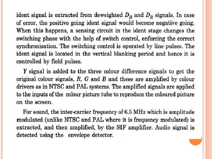
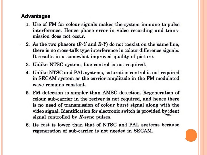
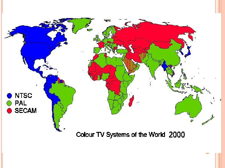
Color Encoding Principles for the SECAM system differs very strongly from PAL and NTSC SECAM uses Frequency Modulation to encode chrominance information on the sub carrier. Second, instead of transmitting the red and blue information together, it only sends one of them at a time Uses the information about the other color from the preceding line. It uses an analog delay line, a memory device, for storing one line of color information. This justifies the "Sequential, With Memory" name.
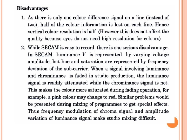
In SECAM the R-Y and B-Y signals are transmitted alternately every line. (The Y signal remains on for each line). Since there is an odd number of lines on any given scan, any line will have R-Y information on the first frame and B-Y on the second Because SECAM transmits only one color at a time, it is free of the color artifacts present in NTSC AND PAL resulting from the combined transmission of both signals. Because the FM modulation of SECAM's color sub carrier is insensitive to phase (or amplitude) errors, phase errors do not cause loss of color saturation in SECAM, although they do in PAL. In NTSC, such errors cause color shifts (hence the "Hue" control on all older NTSC TV sets to adjust the color phase with a constant bias).
Furthermore, the R-Y and B-Y information is transmitted on different subcarriers. The B-Y sub-carrier runs at 4. 25 MHz and the R-Y subcarrier runs at 4. 4 MHz. In order to synchronize the line switching, alternate R-Y and B-Y sync signals are provided for nine lines during he vertical blanking interval following the equalizing pulses after the vertical sync.
SECAM TRANSMITTER Block diagram of a simplified SECAM transmitter is shown in figure below Colour camera tube gives three signal pertaining to three primary colours Red Green and Blue. The Resistive matrix gives Y signal in the same way as in NTSC and PAL. The weighted colour difference signals known as DR and DB are obtained by applying the weighting factors as per Equation. DR = - 1. 9(R –Y) DB = + 1. 5(B-Y)
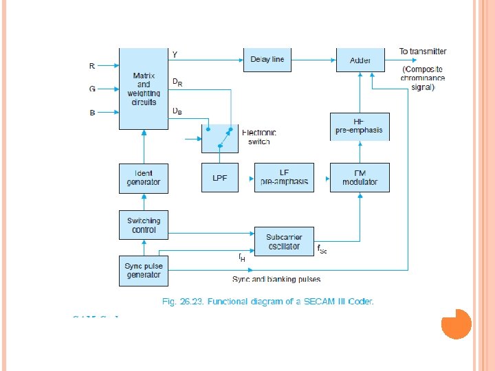
SECAM TRANSMITTER The (CONTI. ) weighted colour difference signals (DB and DR are applied to the terminals of an electronic switch connects the two terminals alternately every 64 micro sec. with the help of sync pulses and a switching control. The output of the switch produces DB and DR in sequence and applies the same to a low pas filter which confines the two signals to 1. 5 M Hz bandwidth. The two band limited based band signals DB and DR undergo pre emphasis to give better signal to noise ratio that the receiver. The Emphasized signal goes to the frequency modulator. The modulator receives the colour sub carrier also. The colour sub carrier oscillator is a harmonic generator with selective filters. The sync pulse of frequency equal to 15. 625 Hz is applied to the input of the harmonic generator which selects two closely spaced harmonic frequencies as follows with the help of sharply tuned filters.
SECAM TRANSMITTER (CONTI. ) For Db 4. 25 M Hz (i. e 272 th harmonic of line frequency For DR 4. 40625 M Hz (i. e 282 th harmonic of line frequency) The reason for using two closely spaced but distinct sub-carrier frequency is to suppress the visibility of dot pattern interference in a monochrome receiver when it is receiving colour transmission. Also the system eliminates phase error as the sub carriers are at the same phase and do not maintain any phase difference. ( In NTSC and PAL, the single carrier has to maintain a phase diff. of 90 degree between two modulators for ensuring quadrature modulation. The nominal value of sub carrier in SECAM system is taken to be equal to 4. 4375 M. Hz. The sequencing of the two freq. is so arranged with the help of a switching control that when DB comes to the modulator, the subcarrier meant for DB (i. e 4. 25 MHz) is applied and when DR comes the sub carrier of 4. 40625 MHz is applied.
SECAM TRANSMITTER (CONTI. ) Max. deviation allowed for frequency modulation colour signals is 500 k. Hz in one direction and 350 k. Hz in the other dirction for each signal. For DR it is -500 k. Hz and 350 KHz while for DB it is +500 k. Hz and -350 k. Hz. It means that freq. deviation for +(RY) is -500 k. Hz and for –(R-Y) +350 KHz. Similarly max. freq. deviation for - (B-Y) is +500 k. Hz and for –(B-Y) -350 k. Hz. Magnitude of the deviation represent colour saturation and rate of deviation represent colour tint. The modulated chroma signal undergoes second pre-emphasis before it goes to he adder to produce CCVS signal. The second pre-emphasis further improves signal to noise ratio and is usually called high freq. Pre emphasis. The modulated carrier (C –signal) along with the indent signal, luminance Y –signal and blanking and sync pulses, all go to an adder which give colour composite video signal. This signal amplitude modulates the main video carrier.
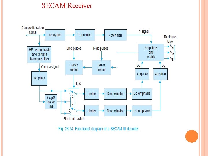
SECAM Receiver
SECAM Receiver (Conti. )
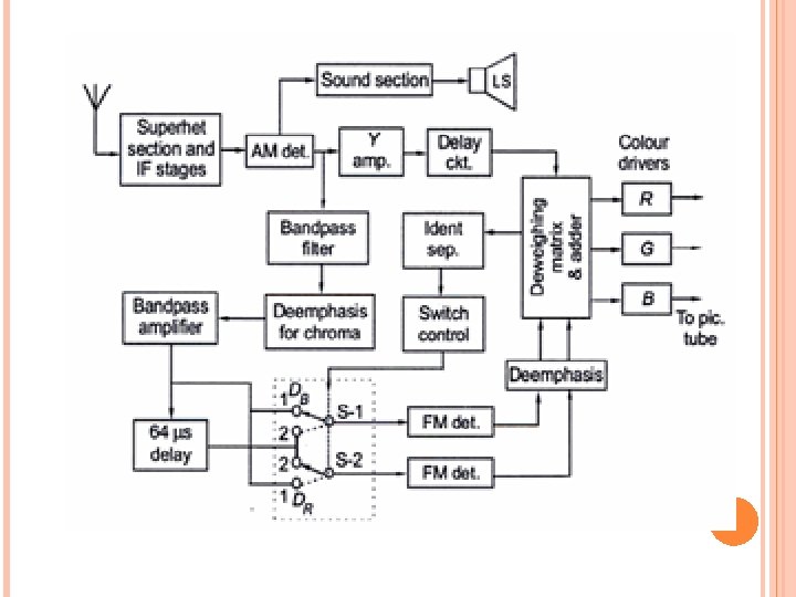
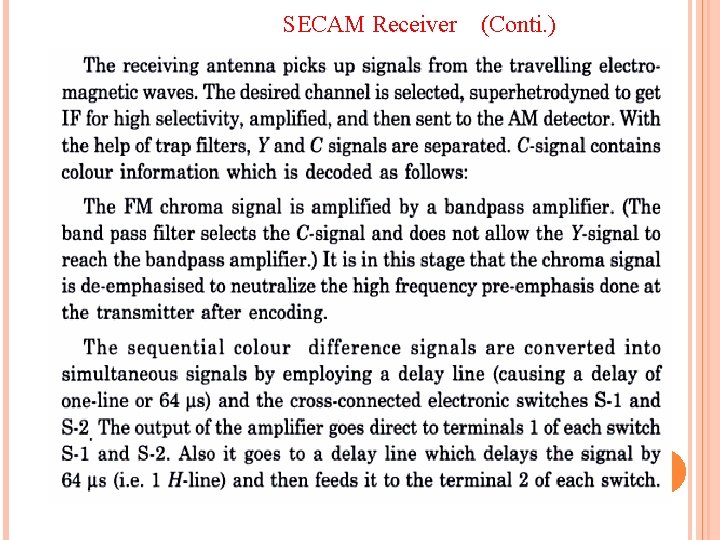
SECAM Receiver (Conti. )
SECAM Receiver (Conti. )
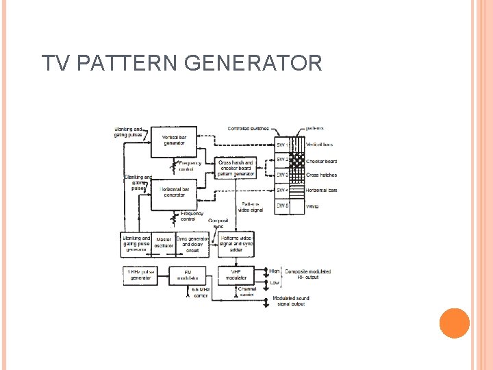
TV PATTERN GENERATOR
- Slides: 80