TE MECH Sub Design Machine Element II UNIT

TE - MECH Sub: -Design Machine Element II UNIT II HELICAL and BEVEL GEAR Prof. (Dr. ) R. S. Hingole Professor & Head Mechanical Engg. Deptt. D. Y. Patil College of Engineering Akurdi Pune

HELICAL GEARS – an introduction In spur gears Fig. 1 dealt earlier, the teeth are parallel to the axis whereas in helical gears Fig. 2 the teeth are inclined to the axis. Both the gears are transmitting power between two parallel shafts. Fig: 1. Spur Gear Fig. 2 Helical gears

Double helical gear or herringbone gear Double helical gear of a cement mill rotary gear drive

WORKING OF SPUR GEAR

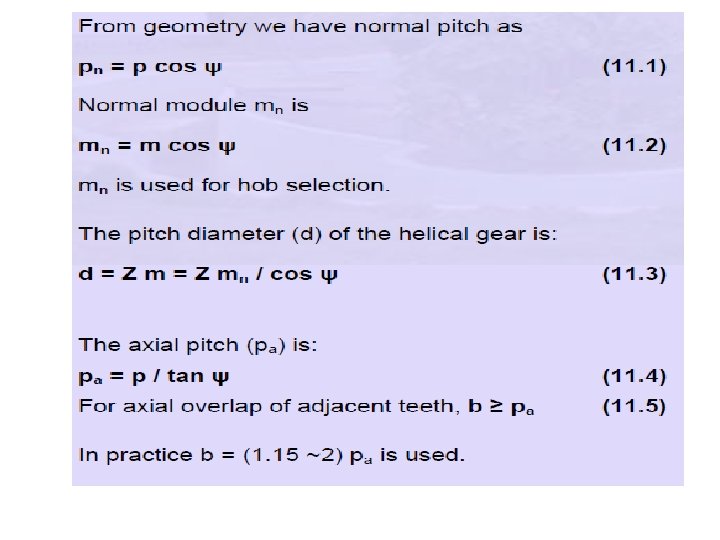
HELICAL GEARS – GEOMETRY AND NOMENCLATURE The helix angle ψ, is always measured on the cylindrical pitch surface Fig. 11. 8. ψ value is not standardized. It ranges between 15 o and 45 o. Commonly used values are 15, 23, 30 or 45 o. Lower values give less end thrust. Higher values result in smoother operation and more end thrust. Above 45 o is not recommended.
 and pressure angle (Ø) are measured in the plane of")
The circular pitch (p) and pressure angle (Ø) are measured in the plane of rotation, as in spur gears. These quantities in normal plane are denoted by suffix n (pn, Øn) as shown in Fig.

The relation between normal and transverse pressure angles is tan Øn = tanØ. cosψ (11. 6) In the case of helical gear, the resultant load between mating teeth is always perpendicular to the tooth surface. Hence bending stresses are computed in the normal plane and the strength of the tooth as a cantilever beam depends on its profile in the normal plane. Fig. 2 shows the view of helical gear in normal and transverse plane. The following figure shows the pitch cylinder and one tooth of a helical gear. The normal plane intersects the pitch cylinder in an ellipse.

Fig. 2

Pitch radius equal to radius Re of the ellipse The equivalent number of teeth (also called virtual number of teeth), Zv, is defined as the number of teeth in a gear of radius Re:

HELICAL GEARS - FORCE ANALYSIS

Resolving Fn

For spur gears, the total tooth force consists of components tangential Ft and radial Fr forces. For helical gears, component Fa is added and normal section NN is needed to show a true view of total tooth force Fn. Fig: The comparison of force components on spur and helical gears

The comparison of force components on spur and helical gears The vector sum Ft and Fa is labeled Fb; the subscript b being chosen because Fb is the bending force on the helical tooth (just as Ft is bending force on the spur tooth)

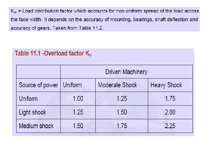
11. 5 HELICAL GEAR - TOOTH BENDING STRESS The bending stress equation for helical gear teeth is given as Introduction of constant 0. 93 with the mounting factor reflects slightly lower sensitivity of helical gears to mounting conditions. The J factor can be determined from Figs. 11. 15 and 1. 16.

Ko = Overload factor which reflects the degree of non-uniformity of driving and load torques.

BEAM STRENTH OF THE HELICAL GEAR Fbn Fb b/ b

Helical gear is equivalent to an imaginary spur gear is known as Virtual Spur Gear in Plane Perpendicular to tooth element To determinr Beam Strength of Helical gear , Helical gear is replaced by Virtual Spur Gear which is in plane Perpendicular to tooth element From Lewis equation Fbn = бb * b’ *mn * Y’ -----------(a) Бb = bending endurance strength or permissible bending strees, N/mm 2 Mn = Normal module, mm Y = Lewis form factor based on virtual no. of teeth, z’ b’ = face width of virtual spur gear, mm = b/ -----------(b) b = Helix angle b = face width of virtual Helical gear, mm
-in-(a) Fbn = бb * b *mn * Y’ -----------(c) The component Fbn")
Put (b)-in-(a) Fbn = бb * b *mn * Y’ -----------(c) The component Fbn in plane of rotation is given by Fb = Fbn * -----------(d) Put (c)-in-(d) Fb = бb * b *mn * Y’ LEWIS EQUATION FOR BEAM STRENTH OF THE HELICAL GEAR
 Y’ = 0.")
LEWIS FORM FACTOR BASED ON VIRTUAL NO. OF TEETH : (Y’) Y’ = 0. 484 – 2. 87 Z’ FOR 200 FULL DEPTH INVOLUTE Y’ = 0. 55 – 2. 64 Z’ FOR 200 STUD INVOLUTE Y’ = 0. 39 – 2. 15 Z’ FOR 14. 50 FULL DEPTH INVOLUTEAND COMPOSITE

ØBENDING ENDURANCE STRENGTH : бb = Sut 3 Where Sut – utlimate tensile strength N/mm 2 ØFACE WIDTH : 9 mn<= b <= 15 mn ØWEAKER OF GEAR AND PINION If (бb × Y’ ) pinion < (бb × Y’ ) gear : Pinion is weaker in bending If (бb × Y’ ) pinion > (бb × Y’ ) gear : Gear is weaker in bending

WEAR STRENTH OF THE HELICAL GEAR Fwn Fw b/ b

Buckingham’s equation for Wear Strength of Virtual Spur Gear in plane Perpendicular to tooth element (i. e normal palne ) Is given by equation Fw = dp * b’ *Q’ * K’ -----------(a) Where d’p = Pitch circle dia. Of virtual spur pinion, mm = dp/

DESIGN OF BEVEL GEARS Bevel gears transmit power between two intersecting shafts at any angle or between non- intersecting shafts. They are classified as straight and spiral tooth bevel and hypoid gears as in Fig. 13. 1 Fig. 1(a) Bevel gear, (b) Straight bevel gear, (c) Spiral bevel gear (d) Hypoid gear

GEOMETRY AND TERMINOLOGY When intersecting shafts are connected by gears, the pitch cones (analogous to the pitch cylinders of spur and helical gears) are tangent along an element, with their apexes at the intersection of the shafts as in Fig. 13. 2 where two bevel gears are in mesh.

The tooth profiles resemble those of spur gears having pitch radii equal to the developed back cone radii rbg and rbp and are shown in Fig. 13. 3. which explains the nomenclatures of a bevel gear. Fig. 13. 3 Bevel gear nomenclature

where Zv is called the virtual number of teeth, p is the circular pitch of both the imaginary spur gears and the bevel gears. Z 1 and Z 2 are the number of teeth on the pinion and gear, γ 1 and γ 2 are the pitch cone angles of pinion and gears.

TREDGOLD’S APPROXIMATION Bevel gear teeth are inherently non - interchangeable. The working depth of the teeth is usually 2 m, the same as for standard spur and helical gears, but the bevel pinion is designed with the larger addendum ( 0. 7 working depth). This avoids interference and results in stronger pinion teeth. It also increases the contact ratio. The gear addendum varies from 1 m for a gear ratio of 1, to 0. 54 m for ratios of 6. 8 and greater. The gear ratio can be determined from the number of teeth, the pitch diameters or the pitch cone angles as,
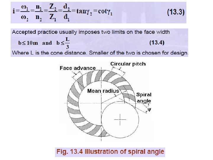

The Fig. 13. 5 illustrates Zero bevel gears, which are having curved teeth like spiral bevels. But they have a zero spiral angle.
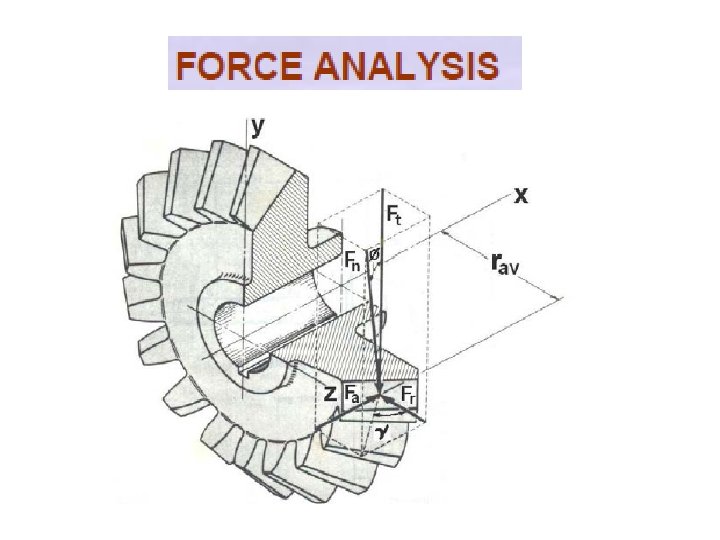
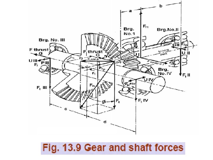

Fn is normal to the pitch cone and the resolution of resultant tooth force Fn into its tangential (torque producing) Ft , radial (separating) Fr and axial (thrust) Fa components(which is normal to the tooth profile). An auxiliary view is needed to show the true length of the vector representing resultant force Fn

Fig. 13. 11 Linear tooth force distribution Resultant force Fn is shown applied to tooth at the pitch cone surface and midway along tooth width b.

It is also assumed that load is uniformly distributed along the tooth width despite the fact that the tooth width is larger at the outer end.

Where is used in the preceding equation, the upper sign applies to a driving pinion with right-hand spiral rotating clockwise as viewed from its large end and to a driving pinion with left-hand spiral rotating counter clock-wise when viewed from its large end. The lower sign applies to a left-hand driving pinion rotating clockwise and to a driving pinion rotating counter clockwise. Similar to helical gears, φn is the pressure angle normal measured in a plane normal to the tooth.

TOOTH BENDING STRESS The equation for bevel gear bending stress is the same as for spur gears as shown below:
- Slides: 38