TCPIP Protocol 1 TCPIP Overview Host Internet TCPIP


 ü 연결지향 프로토콜 ü 사용자 프로세스에게 신뢰성")


 Connection. Oriented User Datagram")
")
의 TCP Port 23번이 Port Address로 할당되어 Telnet Service는")


 SYN received")
 SYN received")
 SYN received")
 SYN received")


 Application Transport Internet Control Message Protocol (ICMP) Address")
를 보고, 네트워크에 대한 최적의 경로를")
 Bit 15 Header Length (4) Bit")
와 서비스유형(4 bit)의 서브필드로 구성 § Precedence Field(3 bit) :")
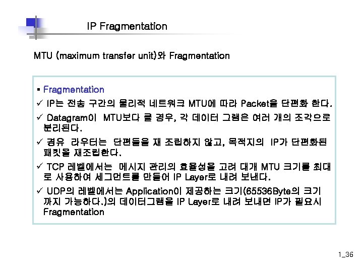
와 Fragmentation § MTU(Maximum Transport Unit) ü 두 노드간")
 : 16비트 필드 ü 발신지 호스트가 전송하는")
 : 3비트 필드 ü 처음 비트 :")
 § IP Packet 전송을 위해서는 Destination의 MAC Address를 알아내어 Frame의 Header에")

 I heard that broadcast. Your IP address is 172. 16. 3. 25.")


- Slides: 53
TCP/IP Protocol 1
TCP/IP Overview Host Internet TCP/IP 1_3
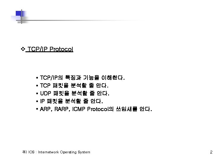
TCP/IP Overview 정의 § ISO/OSI 계층 4 Transport Protocol에 해당 § Transmission Control Protocol/Internet Protocol § 미 국방성(DOD)에서 이기종 컴퓨터간의 통신 및 자원을 공유하기 위한 목적으 로 개발된 미 국방성용 Protocol § 신뢰할 수 없는 Network 환경에 접속된 컴퓨터간의 신뢰적인 통신을 위해 설계 된 Program의 집단 배경 § 1969 : ARPANET 시작 § Advanced Research Projects Agency(미 국방성 고등연구 프로젝트국) § 1972 : ARPANET의 Demo § 1970 중반 : UNIX(DEC PDP-11)와 TCP/IP의 관계가 시작 § 1980 : 미 국방성의 Protocol로서 채택 § 1980 초반 : NCP와 TCP를 포함하는 Berkeley UNIX발표 § TCP/IP가 DOD(Department of Defense: 미국방성)의 표준으로 확정 § 1983 : TCP/IP가 Military Standard Specification이 됨 1_4
TCP/IP 프로토콜 TCP/IP Protocol Stack별 기능 TCP/IP Protocol OSI 7 Layer Model Application Presentation Session Transport Network Data Link Physical Port No. Protocol No. F T P 21 Transport Internet Network Interface T E L N E T 23 S M T P D N S T F T P S N M P 25 53 69 161 TCP IP 6 ICMP UDP ARP 17 RARP Network Interface OSI 7계층 모델과 TCP/IP 프로토콜 모델의 비교 1_6
TCP/IP와 OSI 모델 Application Presentation FTP 21 TELNET 23 SMTP 25 DNS 53 TFTP 69 … SNMP 161 Session Transport layer Network layer Data Link layer Physical layer TCP IGMP ICMP UDP IP ARP RARP Protocols defined by the underlying networks 1_7
TCP/IP Protocol Stack Application Presentation Session Application 4 Transport Network Internet Data Link Physical 3 1_8
TCP/IP Protocol 구조 § TCP(Transmission Control Protocol) ü 연결지향 프로토콜 ü 사용자 프로세스에게 신뢰성 있는 full-duplex, byte stream 서비스를 지원한다. ü 대부분의 인터넷 응용들은 TCP를 사용한다. § UDP(User Data Protocol) ü 비연결 프로토콜 ü UDP datagram의 목적지 도달을 보장 못함 § ICMP(Internet Control Message Protocol) ü 호스트와 게이트웨이간의 에러 및 제어 정보를 제어 § IP(Internet Protocol) ü TCP, UDP, 및 ICMP를 위한 패킷 전달 서비스를 제공 § ARP(Address Resolution Protocol) ü IP 주소를 Hardware 주소로 매핑 § RARP(Reverse ARP) ü Hardware 주소를 IP 주소로 매핑 1_9
Data Encapsulation & Decapsulation 데이터에 제어 정보를 Header 형태로 추가 데이터에 제어 정보 기록한 Header 제거 Application program Message from application program TCP header IP header Frame header TCP Data IP header IP Data Frame Data Encapsulation Frame header TCP Data IP Data Frame Data Decapsulation 1_10
데이터의 계층별 데이터 명칭 Layer TCP UDP Application Layer stream message Transport Layer segment packet Internet Layer Network Access Layer datagram frame 1_11
Application Layer Application Transport Internet Data Link Physical File Transfer - TFTP * - NFS E-Mail - SMTP Remote Login - Telnet * - rlogin * Network Management - SNMP * Name Management - DNS* § Application Protocol사이의 데이터 교환을 책임지는 계층. 1_12
TCP/IP Transport Layer Overview Application Transport Transmission Control Protocol (TCP) Connection. Oriented User Datagram Protocol (UDP) Connectionless Internet Data Link Physical 1_13
TCP Segment Format Bit 0 Bit 15 Bit 16 Bit 31 Destination port (16) Source port (16) Sequence number (32) Acknowledgement number (32) Header length (4) Reserved (6) Code bits (6) 20 Bytes Window (16) Checksum (16) Urgent (16) Options (0 or 32 if any) Data (varies) 1_15
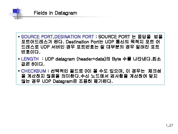
TCP Port Numbers § Telnet Service(Daemon)의 TCP Port 23번이 Port Address로 할당되어 Telnet Service는 23번 포트를 Listening한다. § 원격의 Telnet Client가 Telnet Server의 해당 IP Address와 23번 Destination Port Address로 Telnet Service를 요청하면 23번 포트를 Listening하던 Telnet Service가 응답하여 Telnet Service가 이루어지게 된다. § Port Address 1 -65535까지의 할당이 가능 § 0 - 1023번 까지의 Port Address는 Well-Known Port Address라 하여, 이미 특 정 서비스로 정의된 Address 이다. Application Layer Transport Layer F T P T E L N E T S M T P D N S T F T P S N M P R I P 21 23 25 53 69 161 520 TCP UDP Port Numbers 1_17
TCP Port Numbers Source Port Dest. Port … Telnet Z Host A SP DP 1028 23 … Dest. port = 23. Send packet to my Telnet application. 1_18
TCP 연결설정 및 연결종료 § TCP는 Connection Oriented Protocol로 노드간 데이터 교환 전에 세션을 형성 한다. Three Hand-Shaking이라는 Process에 의해 누 노드간에 Virtial Circuit을 생성하고, 데이터를 교환한다. 데이터 교환이 끝나면 Two Hans-Shaking에 의 해 Session을 종결한다. § 연결설정을 통하여 초기 Sequence No, Window 사이즈, MTU 사이즈 등의 정보 를 교환한다. Host A Host B 1 Send SYN (seq=100 ctl=SYN) SYN received 3 Send SYN, ACK 2 (seq=300 ack=101 ctl=syn, ack) Established (seq=101 ack=301 ctl=ack) 1_19
TCP Handshake/Open Connection Host A 1 Host B Send SYN (seq=100 ctl=SYN) SYN received 1_20
TCP Handshake/Open Connection Host A 1 Host B Send SYN (seq=100 ctl=SYN) SYN received 2 SYN received Send SYN (seq=300 ack=101 ctl=syn, ack) 1_21
TCP Handshake/Open Connection Host A 1 Host B Send SYN (seq=100 ctl=SYN) SYN received 2 SYN received 3 Send SYN (seq=300 ack=101 ctl=syn, ack) Established (seq=101 ack=301 ctl=ack) 1_22
TCP Handshake/Open Connection Host A 1 Host B Send SYN (seq=100 ctl=SYN) SYN received 2 SYN received 3 Established (seq=101 ack=301 ctl=ack) 4 Established (seq=101 ack=301 ctl=ack Data) Send SYN (seq=300 ack=101 ctl=syn, ack) 1_23
TCP Sequence & Acknowledgment Source Port Dest. Port I just sent #11. Sequence # Acknowledgement # … I just got #11, now I need #12. 1028 Dest. 23 Seq. 10 Ack. 1 Source 23 1028 1 11 Source Dest. Seq. Ack. 1028 23 11 2 23 1028 2 12 Source Dest. Seq. Ack. 1_24
TCP Windowing ACK 2 Window size = 3 Send 1 Sender Window size = 3 Send 2 Receiver Window size = 3 Send 3 ACK 3 Window size = 2 Packet 3 is Dropped Window size = 3 Send 3 Window size = 3 Send 4 Window filed ACK 5 Window size = 2 § 흐름제어를 위하여 수신 TCP는 자신이 준비해 놓은 Octet (1 Byte)수를 지정하 여 알린다. § 송신 TCP는 이를 참조하여, 슬라이딩 윈도우 수를 조절할 수 있다. 이 필드의 길이가 16 bit이므로 윈도우의 최대 크기는 65, 535 바이트이다. 1_25
UDP Segment Format Bit 1 0 Bit 15 Bit 16 Bit 31 Destination port (16) Source port (16) Length (16) Checksum (16) 8 Bytes Data (if any) § No sequence or acknowledgment fields 1_26
Internet Layer Overview Internet Protocol (IP) Application Transport Internet Control Message Protocol (ICMP) Address Resolution Protocol (ARP) Data Link Physical Reverse Address Resolution Protocol (RARP) § OSI network layer corresponds to the TCP/IP internet layer 1_28
Internet Protocol Overview § 패킷의 목적지 주소(Destination IP Address)를 보고, 네트워크에 대한 최적의 경로를 찾아 패킷을 전송한다. § IP 자체는 Connection-less로 패킷 손실, 중복, 지연, 순서 바뀜 등이 가 능한 상황에서의 Best Effort 전달시스템이다. § IP Process는 각 호스트와 라우터 등에서 작동된다. § IP의 데이터로는 TCP, UDP, ICMP, IGMP 등이 있다. Protocol Field Transport Layer Internet Layer TCP UDP 6 17 Protocol Numbers icmp igmp tcp udp 1 2 6 17 IP 1_29
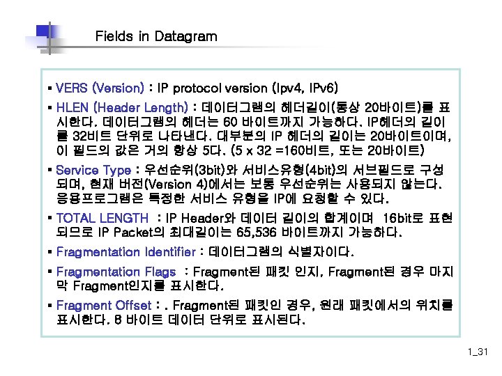
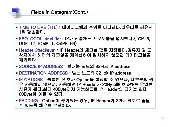
IP Datagram Format Bit 1 0 Version (4) Bit 15 Header Length (4) Bit 31 Priority & Type of Service (8) Total Length (16) Flags (3) Identification (16) Time to live (8) Bit 16 Protocol (8) Fragment offset (13) Header checksum (16) 20 Bytes Source IP Address (32) Destination IP Address (32) Options (0 or 32 if any) Data (varies if any) 1_30
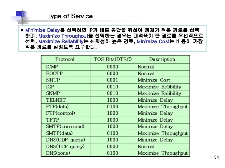
Type of Service 우선순위(3 bit)와 서비스유형(4 bit)의 서브필드로 구성 § Precedence Field(3 bit) : 0 -7까지의 패킷 전송 우선순위를 부여할 수 있다. 현재 사용 안 한다. § TOS field(4 bit)의 권장 값(통상 DTRC가 모두 0인 Normal Mode로 사 용한다. ) 응용프로그램은 특정한 서비스 유형을 IP에 요청할 수 있다. D : Minimize Delay T : Maximize Throughput R : Maximize Reliability C : Minimize Cost 0 1 precedence 2 3 4 5 6 D T R C 7 unused 1_33
IP Fragmentation MTU (maximum transfer unit)와 Fragmentation § MTU(Maximum Transport Unit) ü 두 노드간 물리적 네트워크에 대한 데이터 필드 최대 크기 ü Ethernet 인 경우 최종 데이터 프레임이 1518 Byte까지 이다. ü IP 데이터그램의 최대 가능 크기는 65536 바이트이다. ü (Total Length Field가 16비트이므로 2의 16승의 크기까지 가능하다. ) Protocol Hyper. Channel FDDI DIX Ethernet X. 25 MTU Protocol MTU 65, 535 byte 16 Mbps Token Ring 17, 914 byte 4, 352 byte 4 Mbps Token Ring 4, 464 byte 1, 500 byte 802. 3 1, 492 byte 576 byte PPP 296 byte 서로 다른 네트워크의 MTU 1_35
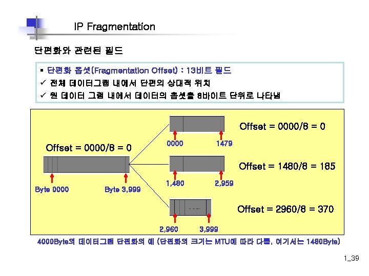
IP Fragmentation 단편화와 관련된 필드 § 식별자(Identification) : 16비트 필드 ü 발신지 호스트가 전송하는 데이터그램을 지정 ü 보통 매번 값을 1씩 증가 시킨다. ü 식별자와 IP 주소의 조합은 데이터그램이 발신지를 떠날 때 유일하게 정의되어 야함 ü 데이터그램이 단편화 될 때 식별자 필드값은 모든 단편에 복사됨 Original packet 4 5 0 2000 0324 0 000 05 06 checksum 128. 83. 24. 13 192. 10. 2. 5 DATA 1980 Bytes First fragment 4 5 0 1500 0324 1 000 05 06 checksum 128. 83. 24. 13 192. 10. 2. 5 DATA 1480 Bytes Second fragment 4 5 0 520 0324 0 185 05 06 checksum 128. 83. 24. 13 192. 10. 2. 5 DATA 500 Bytes Fragmentation Identifier 필 드에 동일한 일련번호를 공유 ( 동일한 데이터그램) 1_37
IP Fragmentation 단편화와 관련된 필드 § 플래그(Flag) : 3비트 필드 ü 처음 비트 : 사용하지 않음(Reserved Flag ) - 0 ü 두 번째 비트 : Do not Fragment 비트. 1이면 단편화 해서는 안됨 ü 세 번째 비트 : More Fragment 비트. 1이면 데이터 그램이 마지막 단편이 아니 라는 것을 의미. 0이면 마지막 단편이거나, 유일한 단편임 Original packet 4 5 0 2000 0324 0 000 05 06 checksum 128. 83. 24. 13 192. 10. 2. 5 DATA 1980 Bytes First fragment 4 5 0 1500 0324 1 000 05 06 checksum 128. 83. 24. 13 192. 10. 2. 5 DATA 1480 Bytes Second fragment 4 5 0 520 0324 0 185 05 06 checksum 128. 83. 24. 13 192. 10. 2. 5 DATA 500 Bytes 플래그의 사용 예 (More Fragment Bit만 표시 한 것임) 1_38
ARP(Address Resolution Protocol) § IP Packet 전송을 위해서는 Destination의 MAC Address를 알아내어 Frame의 Header에 DA로 설정해야 Frame 형태로 전송할 수 있다. IP는 ARP 프로토콜에 요청하여 IP Address에 대한 Layer 2 Address(MAC Address)를 알아내도록 하 는데 IP Address를 MAC Address로 변환해주는 Protocol을 ARP라 한다. ARP 는 Local Broadcasting에 의존한다. ARP는 한번 찾은 Address는 ARP Cache에 일정기간 IP Address-MAC Address형태로 보관한다. I need the I heard that broadcast. Ethernet address The message is for me. of 176. 16. 3. 2. Here is my Ethernet address. 172. 16. 3. 1 172. 16. 3. 2 IP: 172. 16. 3. 2 = ? ? ? IP: 172. 16. 3. 2 Ethernet: 0800. 0020. 1111 1_41
RARP(Reverse ARP) I heard that broadcast. Your IP address is 172. 16. 3. 25. What is my IP address? Ethernet: 0800. 0020. 1111 IP = ? ? ? Ethernet: 0800. 0020. 1111 IP: 172. 16. 3. 25 § Map Ethernet = IP § ARP와 RARP는 데이터링크 계층과 직접 관여가 됨 1_43
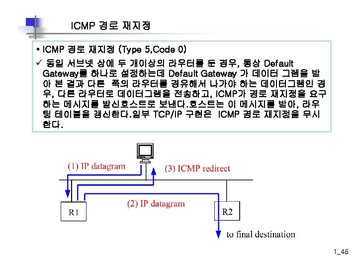
Network Unreachable 192. 168. 39. 10 으로 전송되는 패킷 Bhkang 192. 168. 10. 1 ROUTER 192. 168. 10. 254 192. 168. 20. 254 Server 192. 168. 20. 1 ICMP: Network Unreachable § Destination Unrechable (Type 3, Code 0 -15) ü net/host/protocol/port가 unreachable 하는 등, 라우터가 데이터그램 을 전송 할 수 없을 때 발생된다. 1_45
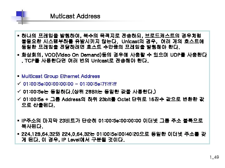
Multicast & IGMP Unicast, Broadcast, Muticast § Unicast : 하나의 호스트를 Destination으로 한다. Ethernet Frame Header의 DA가 하나의 MAC Address를 나타낸다. (예. 00 -50 -04 -F 2 -A 7 -3 B) Destination IP Address가 특정 IP Address이다. (예. 150. 21. 32. 250) § Broadcast : 모든 호스트가 Destination이다. Ethernet Frame Header의 DA가 모든 MAC Address를 나타낸다. (FF-FF-FFFF)Destination IP Address가 Broadcast IP Address이다. (예. 150. 21. 255 또는 255) § Multicast : 멀티캐스트 그룹에 속하는 호스트가 Destination이다. Ethernet Frame Header의 DA가 그룹 MAC Address를 나타낸다. Destination IP Address가 Multicast IP Address이다. 1_47
Broadcast Address 172. 16. 3. 0 172. 16. 4. 0 172. 16. 1. 0 172. 16. 2. 0 172. 16. 3. 255 (Directed broadcast) 255 (Local broadcast) X 172. 16. 1. 255 (subnets broadcast) 1_48
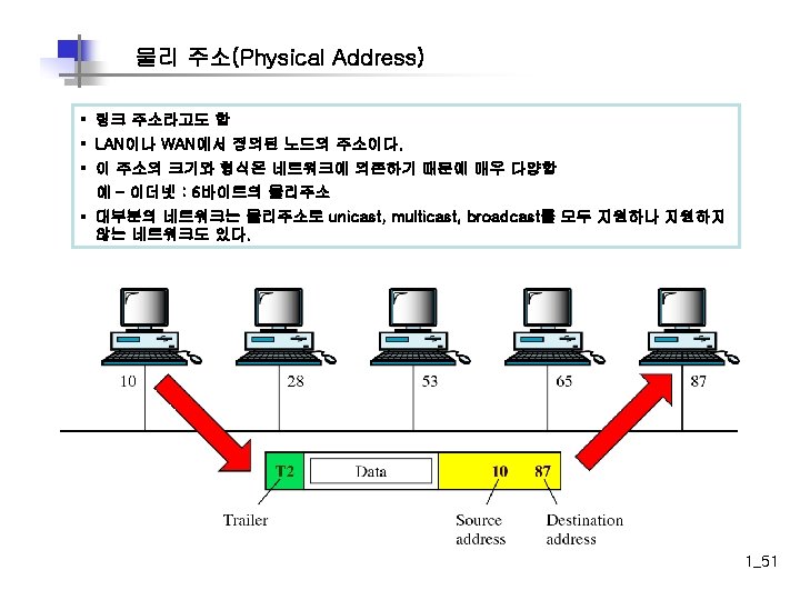
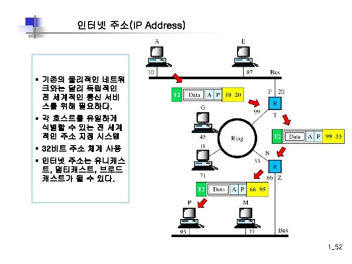
주소 지정 TCP/IP에서 사용하는 주소 Addresses Physical Address IP Address Port Address 1_50