
Task Switching The multitaskingmultiuser OS needs the ability
Task Switching • The multitasking/multiuser OS needs the ability to rapidly switch between tasks. • Intel 386 DX supports this operation by providing a task switch instruction hardware. • The task switch operation – saves the entire state of the machine(all of reg. s, address space and a link to previous task), – loads a new execution state, – performs protection checks and – commences execution in the new task in about 17 μs. 1
Task Switching • The task switch operation is invoked by an intersegment JMP or CALL instruction which refers to a TSS or task gate descriptor in GDT or LDT • The TSS Descriptor points to a segment containing the entire execution state while a Task Gate Descriptor contains a TSS Selector 2
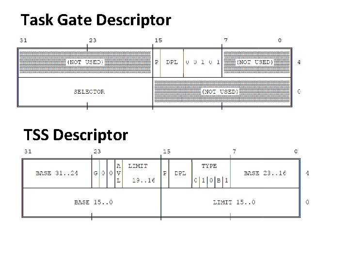
Task Gate Descriptor TSS Descriptor
Task Switching • Each task must have a TSS associated with it. • The current TSS is identified by the Task State Segment Register(TR) • TR contains the selector referring to current TSS Descriptor. • Returning from a task is done by IRET • IRET makes the control transfer to the task which was interrupted and current task state is saved in TSS and old task state is restored from TSS 4
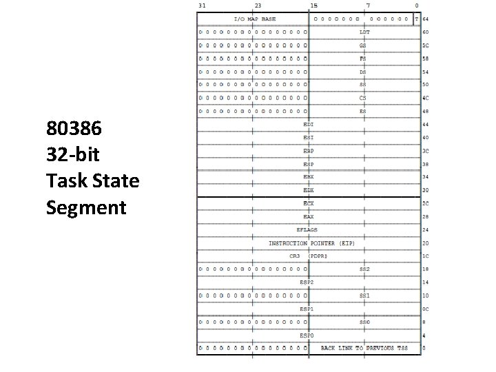
80386 32 -bit Task State Segment
Task State Segment(TSS) • All information the processor needs to manage a task is stored in task state segment (TSS). • The fields of a TSS belong to two classes: • Dynamic set : processor updates with each task switch. It includes the fields that store: – General registers (EAX, ECX, EDX, EBX, ESP, EBP, ESI, EDI) – The segment registers (ES, CS, SS, DS, FS, GS). – The flags register (EFLAGS). – The instruction pointer (EIP). – The selector of the TSS
Task State Segment(TSS) • Static set : the processor reads but does not change. • This set includes the fields that store: – The selector of the task's LDT. – Page Directory Base Register (PDBR) – Pointers to the stacks. – T-bit (debug trap bit) – I/O map base
Virtual 8086 UQ: Write short note on V-86 mode of operation(05 Marks)
Virtual 8086 • It allows the execution of 8086 applications with protection mechanism • It allows simultaneous execution of 8086 OS and its applications 9
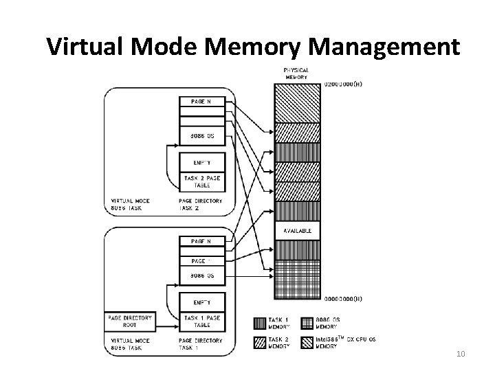
Virtual Mode Memory Management 10
Virtual Mode Addressing Mechanism • The segment registers are used as in REAL mode • The contents of segment register is shifted by 4 bits and added to offset to form linear address 11
Paging in Virtual Mode • It allows concurrent running of multiple VM tasks and provide protection and OS isolation • Paging is not necessary but for multiple tasks it is required • Paging allows 20 -bit linear address to form 256 pages and can be allocated anywhere in 4 GB physical memory 12
Paging in Virtual Mode • Since CR 3 is loaded by a task switch, each VM task can use a different mapping scheme to map pages to different physical location • The paging hardware allows the sharing of 8086 OS b/w multiple 8086 applications. 13
- Slides: 13