
TAPI and RFC 8345 Network Topology Analysis Stephane
- Slides: 19
TAPI and RFC 8345 Network Topology Analysis Stephane St-Laurent, Infinera September 9, 2019
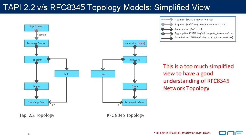
TAPI 2. 2 v/s RFC 8345 Topology Models: Simplified View Augment (YANG augment + uses) Augment (YANG augment + uses + container) Tapi. Context Composition (YANG list) Aggregation (YANG leafref + require_instance=true) (ROOT) Augment Association (YANG leafref + require_instance=false) Topology. Context Networks (ROOT) Topology Network Link Node. Edge. Point Node 2. . * Tapi 2. 2 Topology 2 2 This is a too much simplified view to have a good understanding of RFC 8345 Network Topology Termination. Point RFC 8345 Topology * all TAPI & RFC 8345 associations not shown
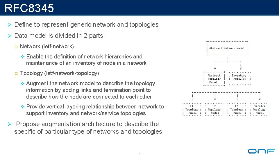
RFC 8345 Ø Define to represent generic network and topologies Ø Data model is divided in 2 parts q Network (ietf-network) v Enable the definition of network hierarchies and maintenance of an inventory of node in a network q Topology (ietf-network-topology) v Augment the network model to describe the topology information by adding links and termination point to describe how the node are connected to each other v Provide vertical layering relationship between network to support inventory and network/service topologies Ø Propose augmentation architecture to describe the specific of particular type of networks and topologies 3
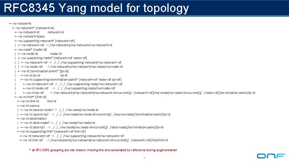
RFC 8345 Yang model for topology +--rw networks +--rw network* [network-id] +--rw network-id +--rw network-types +--rw supporting-network* [network-ref] | +--rw network-ref -> /nw: networks/nw: network-id +--rw node* [node-id] | +--rw node-id | +--rw supporting-node* [network-ref node-ref] | | +--rw network-ref ->. . /nw: supporting-network/nw: network-ref | | +--rw node-ref -> /nw: networks/nw: network/nw: node-id | +--rw nt: termination-point* [tp-id] | +--rw nt: tp-id | +--rw nt: supporting-termination-point* [network-ref node-ref tp-ref] | +--rw nt: network-ref ->. . /nw: supporting-node/nw: network-ref | +--rw nt: node-ref ->. . /nw: supporting-node/nw: node-ref | +--rw nt: tp-ref -> /nw: networks/nw: network[nw: network-id=current()/. . /network-ref]/nw: node[nw: node-id=current()/. . /node-ref]/termination-point/tp-id +--rw nt: link* [link-id] +--rw nt: link-id +--rw nt: source | +--rw nt: source-node? ->. . /nw: node-id | +--rw nt: source-tp? ->. . /nw: node[nw: node-id=current()/. . /source-node]/termination-point/tp-id +--rw nt: destination | +--rw nt: dest-node? ->. . /nw: node-id | +--rw nt: dest-tp? ->. . /nw: node[nw: node-id=current()/. . /dest-node]/termination-point/tp-id +--rw nt: supporting-link* [network-ref link-ref] +--rw nt: network-ref ->. . /nw: supporting-network/nw: network-ref +--rw nt: link-ref -> /nw: networks/nw: network[nw: network-id=current()/. . /network-ref]/link-id * all RFC 8345 grouping are not shown: missing the one associated to reference during augmentation 4
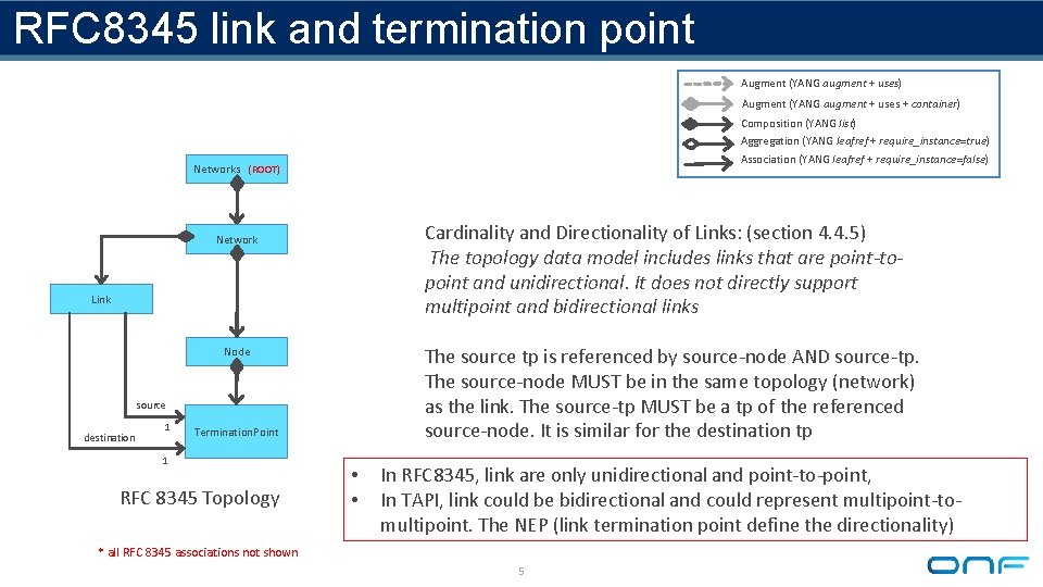
RFC 8345 link and termination point Augment (YANG augment + uses) Augment (YANG augment + uses + container) Composition (YANG list) Aggregation (YANG leafref + require_instance=true) Association (YANG leafref + require_instance=false) Networks (ROOT) Cardinality and Directionality of Links: (section 4. 4. 5) The topology data model includes links that are point-topoint and unidirectional. It does not directly support multipoint and bidirectional links Network Link The source tp is referenced by source-node AND source-tp. The source-node MUST be in the same topology (network) as the link. The source-tp MUST be a tp of the referenced source-node. It is similar for the destination tp Node source destination 1 Termination. Point 1 RFC 8345 Topology • • In RFC 8345, link are only unidirectional and point-to-point, In TAPI, link could be bidirectional and could represent multipoint-tomultipoint. The NEP (link termination point define the directionality) * all RFC 8345 associations not shown 5
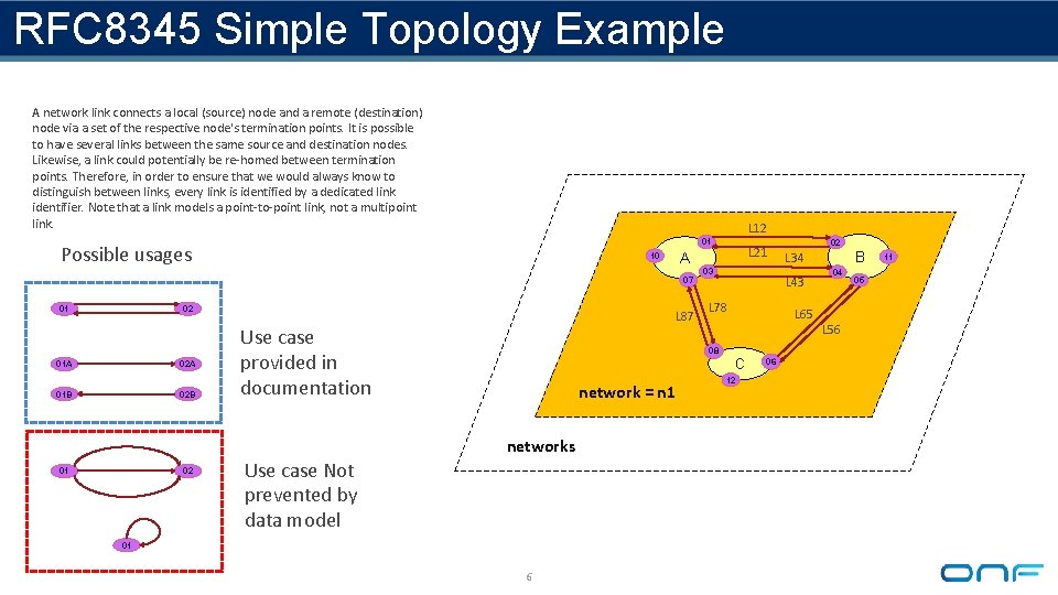
RFC 8345 Simple Topology Example A network link connects a local (source) node and a remote (destination) node via a set of the respective node's termination points. It is possible to have several links between the same source and destination nodes. Likewise, a link could potentially be re-homed between termination points. Therefore, in order to ensure that we would always know to distinguish between links, every link is identified by a dedicated link identifier. Note that a link models a point-to-point link, not a multipoint link. L 12 01 Possible usages 07 01 02 01 A 02 A 01 B 02 B L 87 Use case provided in documentation 02 03 L 78 Use case Not prevented by data model 01 6 12 06 B L 34 L 65 C network = n 1 02 L 43 08 networks 01 L 21 A 10 04 L 56 05 11
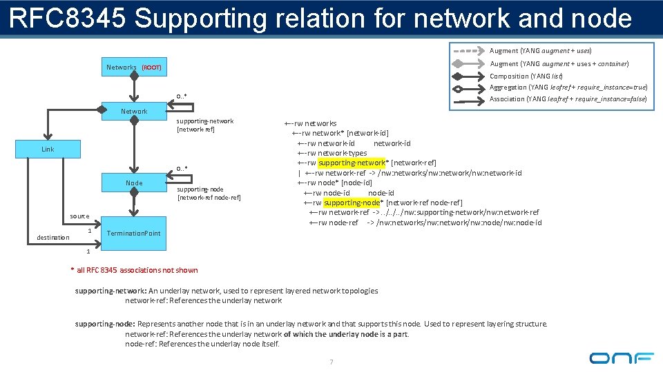
RFC 8345 Supporting relation for network and node Augment (YANG augment + uses) Augment (YANG augment + uses + container) Networks (ROOT) Composition (YANG list) Aggregation (YANG leafref + require_instance=true) 0. . * Association (YANG leafref + require_instance=false) Network supporting-network [network-ref] Link 0. . * Node supporting-node [network-ref node-ref] source destination 1 +--rw networks +--rw network* [network-id] +--rw network-id +--rw network-types +--rw supporting-network* [network-ref] | +--rw network-ref -> /nw: networks/nw: network-id +--rw node* [node-id] +--rw node-id +--rw supporting-node* [network-ref node-ref] +--rw network-ref ->. . /nw: supporting-network/nw: network-ref +--rw node-ref -> /nw: networks/nw: network/nw: node-id Termination. Point 1 * all RFC 8345 associations not shown supporting-network: An underlay network, used to represent layered network topologies. network-ref: References the underlay network supporting-node: Represents another node that is in an underlay network and that supports this node. Used to represent layering structure. network-ref: References the underlay network of which the underlay node is a part. node-ref: References the underlay node itself. 7
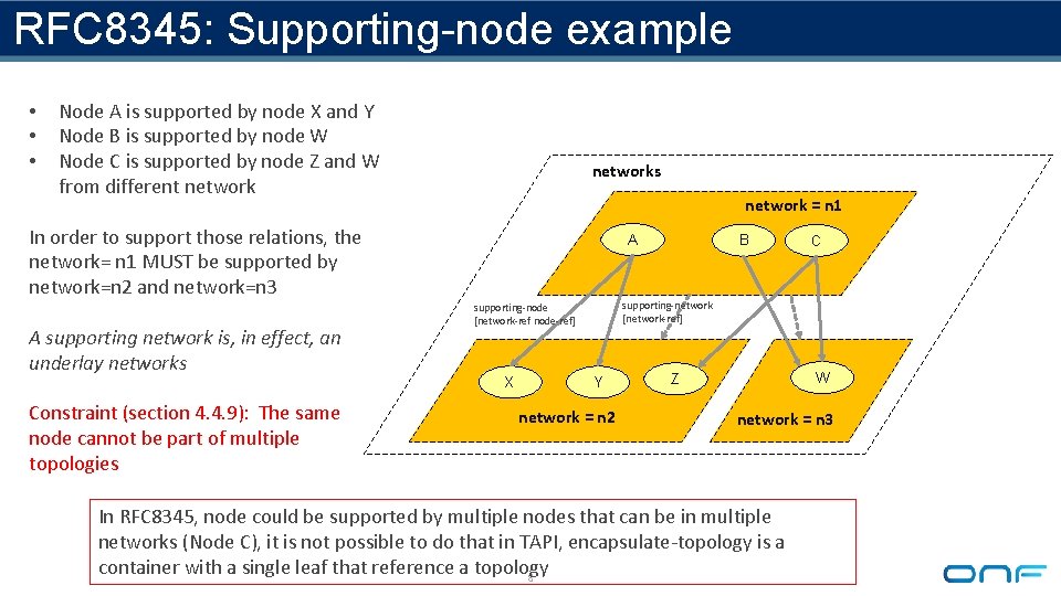
RFC 8345: Supporting-node example • • • Node A is supported by node X and Y Node B is supported by node W Node C is supported by node Z and W from different networks network = n 1 In order to support those relations, the network= n 1 MUST be supported by network=n 2 and network=n 3 A supporting network is, in effect, an underlay networks Constraint (section 4. 4. 9): The same node cannot be part of multiple topologies A C supporting-network [network-ref] supporting-node [network-ref node-ref] X B Y network = n 2 W Z network = n 3 In RFC 8345, node could be supported by multiple nodes that can be in multiple networks (Node C), it is not possible to do that in TAPI, encapsulate-topology is a container with a single leaf that reference a topology 8
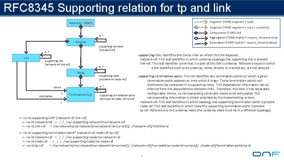
RFC 8345 Supporting relation for tp and link Augment (YANG augment + uses) Networks (ROOT) Augment (YANG augment + uses + container) Composition (YANG list) Aggregation (YANG leafref + require_instance=true) 0. . * Network 0. . * Link supporting-link [network-ref link-ref] 0. . * Node source destination Association (YANG leafref + require_instance=false) supporting-network [network-ref] 1 1 Termination. Point supporting-link: Identifies the link or links on which this link depends network-ref: This leaf identifies in which underlay topology the supporting link is present link-ref: This leaf identifies a link that is a part of this link’s underlay. Reference loops in which a link identifies itself as its underlay, either directly or transitively, are not allowed supporting-node [network-ref node-ref] supporting-termination-point: This list identifies any termination points on which a given termination point depends or onto which it maps. Those termination points will themselves be contained in a supporting node. This dependency information can be 0. . * inferred from the dependencies between links. Therefore, this item is not separately configurable. Hence, no corresponding constraint needs to be articulated. The supporting-termination-point corresponding information is simply provided by the implementing system. [network-ref node-ref tp-ref] network-ref: This leaf identifies in which topology the supporting termination point is present node-ref: This leaf identifies in which node the supporting termination point is present. tp-ref: Reference to the underlay node (the underlay node must be in a different topology). +--rw nt: supporting-link* [network-ref link-ref] +--rw nt: network-ref ->. . /nw: supporting-network/nw: network-ref +--rw nt: link-ref -> /nw: networks/nw: network[nw: network-id=current()/. . /network-ref]/link-id +--rw nt: supporting-termination-point* [network-ref node-ref tp-ref] +--rw nt: network-ref ->. . /nw: supporting-node/nw: network-ref +--rw nt: node-ref ->. . /nw: supporting-node/nw: node-ref +--rw nt: tp-ref -> /nw: networks/nw: network[nw: network-id=current()/. . /network-ref]/nw: node[nw: node-id=current()/. . /node-ref]/termination-point/tp-id 9
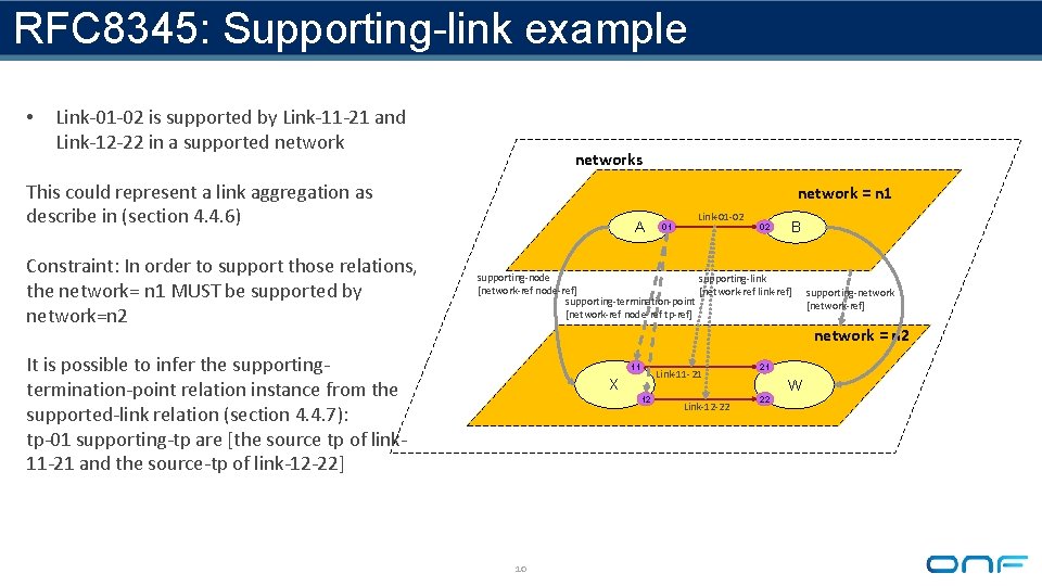
RFC 8345: Supporting-link example • Link-01 -02 is supported by Link-11 -21 and Link-12 -22 in a supported networks This could represent a link aggregation as describe in (section 4. 4. 6) Constraint: In order to support those relations, the network= n 1 MUST be supported by network=n 2 network = n 1 A 01 Link-01 -02 02 B supporting-node supporting-link [network-ref node-ref] [network-ref link-ref] supporting-termination-point [network-ref node-ref tp-ref] supporting-network [network-ref] network = n 2 It is possible to infer the supportingtermination-point relation instance from the supported-link relation (section 4. 4. 7): tp-01 supporting-tp are [the source tp of link 11 -21 and the source-tp of link-12 -22] 11 Link-11 -21 X 12 10 Link-12 -22 21 W 22
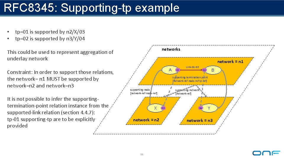
RFC 8345: Supporting-tp example • • tp=01 is supported by n 2/X/03 tp=02 is supported by n 3/Y/04 networks This could be used to represent aggregation of underlay network Constraint: In order to support those relations, the network= n 1 MUST be supported by network=n 2 and network=n 3 It is not possible to infer the supportingtermination-point relation instance from the supported-link relation (section 4. 4. 7): tp-01 supporting-tp are to be explicitly provided network = n 1 A 01 Link-01 -02 B 02 supporting-termination-point [network-ref node-ref tp-ref] supporting-node [network-ref node-ref] X network = n 2 11 supporting-network [network-ref] 03 04 Y network = n 3
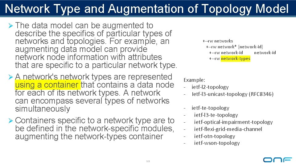
Network Type and Augmentation of Topology Model Ø The data model can be augmented to describe the specifics of particular types of networks and topologies. For example, an augmenting data model can provide network node information with attributes that are specific to a particular network type. Ø A network's network types are represented using a container that contains a data node for each of its network types. A network can encompass several types of networks simultaneously Ø Containers specific to a network type are to be defined in the network-specific modules, augmenting the network-types container 12 +--rw networks +--rw network* [network-id] +--rw network-id +--rw network-types Example: - ietf-l 2 -topology - Ietf-l 3 -unicast-topology (RFC 8346) - ietf-te-topology ietf-l 3 -te-topology ietf-optical-impairment-topology ietf-flexi-grid-media-channel ietf-otn-topology ietf-wson-topology
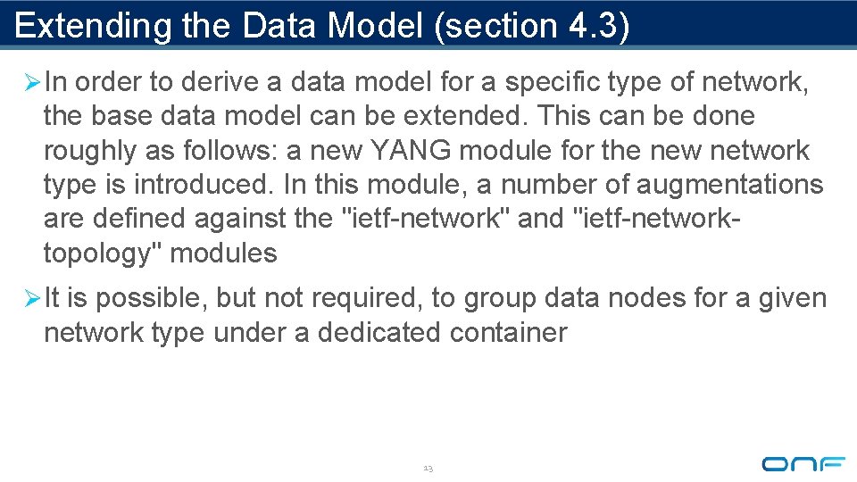
Extending the Data Model (section 4. 3) Ø In order to derive a data model for a specific type of network, the base data model can be extended. This can be done roughly as follows: a new YANG module for the new network type is introduced. In this module, a number of augmentations are defined against the "ietf-network" and "ietf-networktopology" modules Ø It is possible, but not required, to group data nodes for a given network type under a dedicated container 13
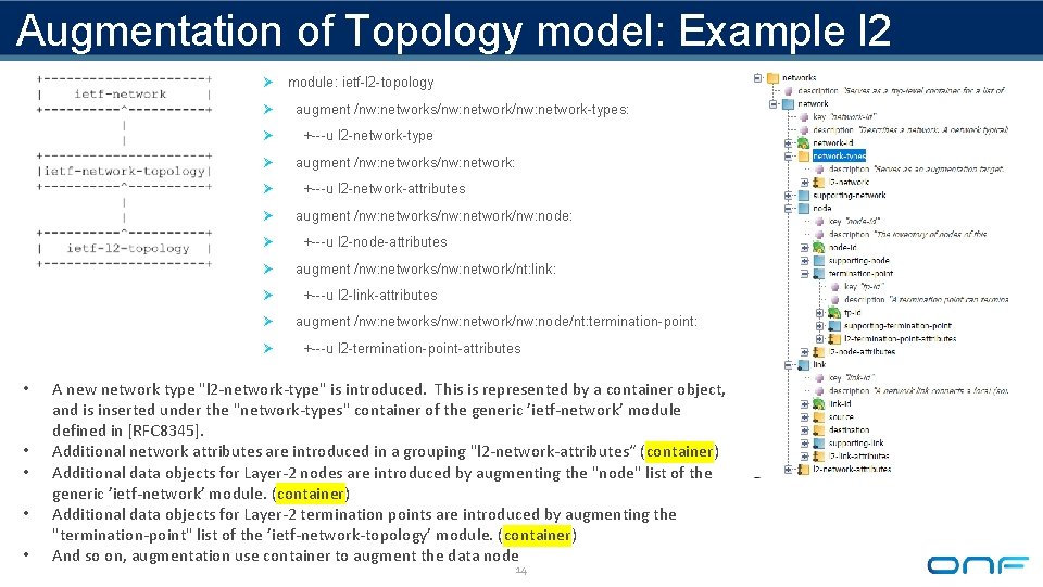
Augmentation of Topology model: Example l 2 Ø Ø Ø • • • module: ietf-l 2 -topology augment /nw: networks/nw: network-types: +---u l 2 -network-type augment /nw: networks/nw: network: +---u l 2 -network-attributes augment /nw: networks/nw: network/nw: node: +---u l 2 -node-attributes augment /nw: networks/nw: network/nt: link: +---u l 2 -link-attributes augment /nw: networks/nw: network/nw: node/nt: termination-point: +---u l 2 -termination-point-attributes A new network type "l 2 -network-type" is introduced. This is represented by a container object, and is inserted under the "network-types" container of the generic ’ietf-network’ module defined in [RFC 8345]. Additional network attributes are introduced in a grouping "l 2 -network-attributes“ (container) Additional data objects for Layer-2 nodes are introduced by augmenting the "node" list of the generic ’ietf-network’ module. (container) Additional data objects for Layer-2 termination points are introduced by augmenting the "termination-point" list of the ’ietf-network-topology’ module. (container) And so on, augmentation use container to augment the data node 14
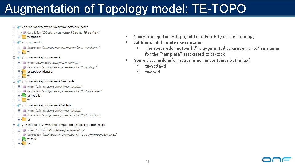
Augmentation of Topology model: TE-TOPO • • • Same concept for te-topo, add a network-type = te-topology Additional data node use container • The root node “networks” is augmented to contain a “te” container for the “template” associated to te-topo Some data node information is not in container but in leaf • te-node-id • te-tp-id 15
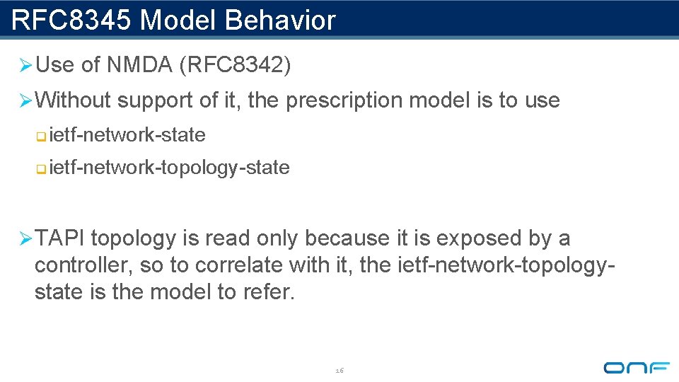
RFC 8345 Model Behavior Ø Use of NMDA (RFC 8342) Ø Without support of it, the prescription model is to use q ietf-network-state q ietf-network-topology-state Ø TAPI topology is read only because it is exposed by a controller, so to correlate with it, the ietf-network-topologystate is the model to refer. 16
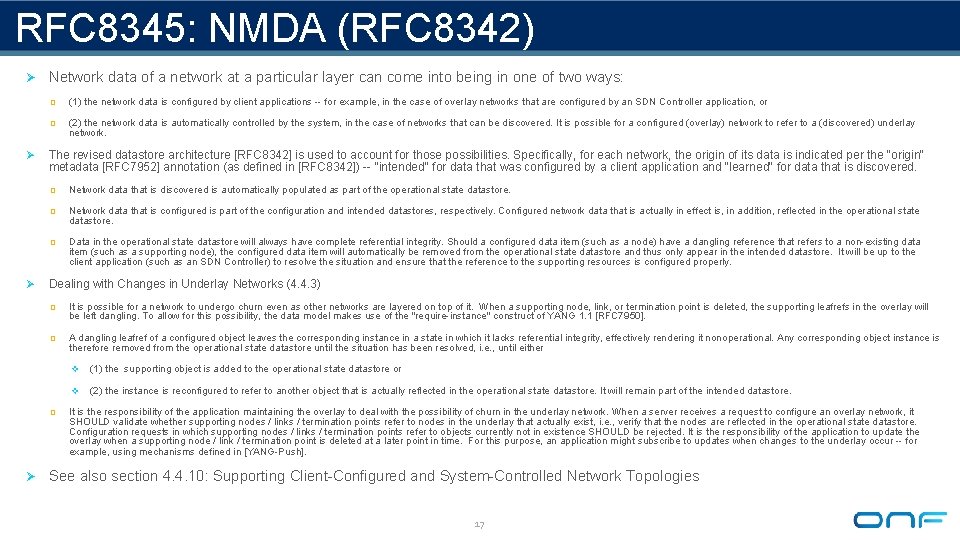
RFC 8345: NMDA (RFC 8342) Ø Network data of a network at a particular layer can come into being in one of two ways: Ø Ø q (1) the network data is configured by client applications -- for example, in the case of overlay networks that are configured by an SDN Controller application, or q (2) the network data is automatically controlled by the system, in the case of networks that can be discovered. It is possible for a configured (overlay) network to refer to a (discovered) underlay network. The revised datastore architecture [RFC 8342] is used to account for those possibilities. Specifically, for each network, the origin of its data is indicated per the "origin" metadata [RFC 7952] annotation (as defined in [RFC 8342]) -- "intended" for data that was configured by a client application and "learned" for data that is discovered. q Network data that is discovered is automatically populated as part of the operational state datastore. q Network data that is configured is part of the configuration and intended datastores, respectively. Configured network data that is actually in effect is, in addition, reflected in the operational state datastore. q Data in the operational state datastore will always have complete referential integrity. Should a configured data item (such as a node) have a dangling reference that refers to a non-existing data item (such as a supporting node), the configured data item will automatically be removed from the operational state datastore and thus only appear in the intended datastore. It will be up to the client application (such as an SDN Controller) to resolve the situation and ensure that the reference to the supporting resources is configured properly. Dealing with Changes in Underlay Networks (4. 4. 3) q It is possible for a network to undergo churn even as other networks are layered on top of it. When a supporting node, link, or termination point is deleted, the supporting leafrefs in the overlay will be left dangling. To allow for this possibility, the data model makes use of the "require-instance" construct of YANG 1. 1 [RFC 7950]. q A dangling leafref of a configured object leaves the corresponding instance in a state in which it lacks referential integrity, effectively rendering it nonoperational. Any corresponding object instance is therefore removed from the operational state datastore until the situation has been resolved, i. e. , until either q v (1) the supporting object is added to the operational state datastore or v (2) the instance is reconfigured to refer to another object that is actually reflected in the operational state datastore. It will remain part of the intended datastore. It is the responsibility of the application maintaining the overlay to deal with the possibility of churn in the underlay network. When a server receives a request to configure an overlay network, it SHOULD validate whether supporting nodes / links / termination points refer to nodes in the underlay that actually exist, i. e. , verify that the nodes are reflected in the operational state datastore. Configuration requests in which supporting nodes / links / termination points refer to objects currently not in existence SHOULD be rejected. It is the responsibility of the application to update the overlay when a supporting node / link / termination point is deleted at a later point in time. For this purpose, an application might subscribe to updates when changes to the underlay occur -- for example, using mechanisms defined in [YANG-Push]. Ø See also section 4. 4. 10: Supporting Client-Configured and System-Controlled Network Topologies 17
TE Topology and Tunnel Modelling draft-ietf-teas-yang-te-topo-22: ietf-te-topology draft-ietf-teas-te-topo-and-tunnel-modeling-04 18
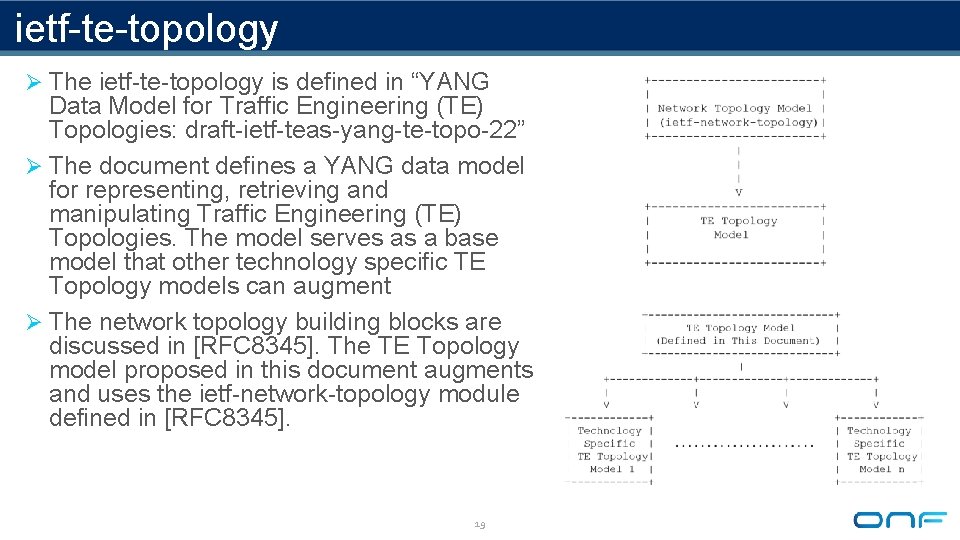
ietf-te-topology Ø The ietf-te-topology is defined in “YANG Data Model for Traffic Engineering (TE) Topologies: draft-ietf-teas-yang-te-topo-22” Ø The document defines a YANG data model for representing, retrieving and manipulating Traffic Engineering (TE) Topologies. The model serves as a base model that other technology specific TE Topology models can augment Ø The network topology building blocks are discussed in [RFC 8345]. The TE Topology model proposed in this document augments and uses the ietf-network-topology module defined in [RFC 8345]. 19