
TALON Frequency Slice Architecture Correlator Beamformer for SKA
TALON Frequency Slice Architecture Correlator / Beamformer for SKA 1_Mid Mike Pleasance Astronomy Technology Directorate – Herzberg Astronomy and Astrophysics ALMA 2030 Vision: Design Considerations for the Next ALMA Correlator, Charlottesville, Virginia February 12, 2020

TALON Technology • Overview • Current Prototyping Status • Planned and Potential Applications 2

Overview • What is the TALON Technology? • TALON-DX General Purpose Signal Processing Board • TALON Line Replaceable Unit (LRU) 3

Overview – TALON-DX • Latest generation Intel Stratix 10 FPGA technology • Huge I/O bandwidth and computational power • Embedded quad-core ARM processor • Up to 640 Gigabytes of memory • 54 x Optical high-speed I/O interfaces • 2 x 40/100 G Ethernet ports • 2 x 1 G Ethernet ports (copper or optical) • Designed with air cooling or liquid cooling in mind Compute + memory + I/O = digital signal processing power! 4
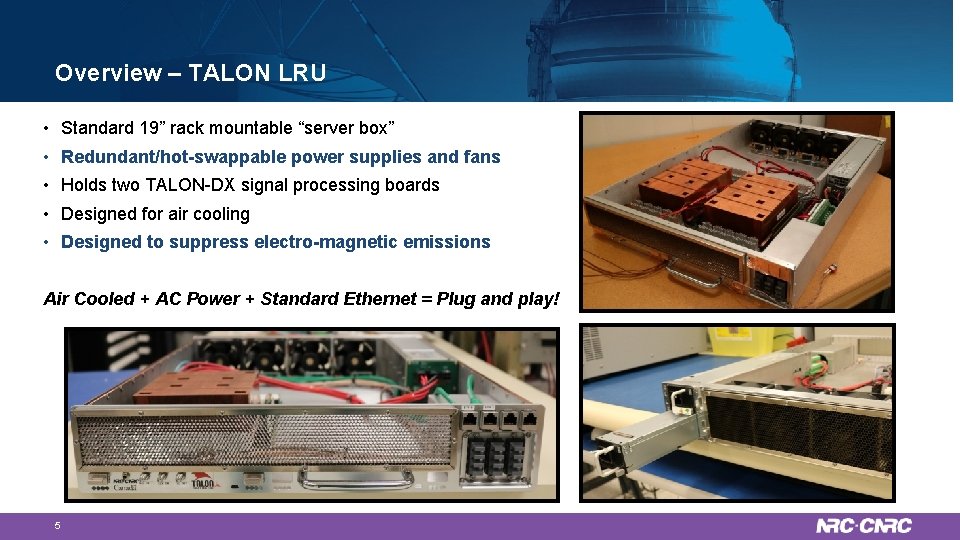
Overview – TALON LRU • Standard 19” rack mountable “server box” • Redundant/hot-swappable power supplies and fans • Holds two TALON-DX signal processing boards • Designed for air cooling • Designed to suppress electro-magnetic emissions Air Cooled + AC Power + Standard Ethernet = Plug and play! 5
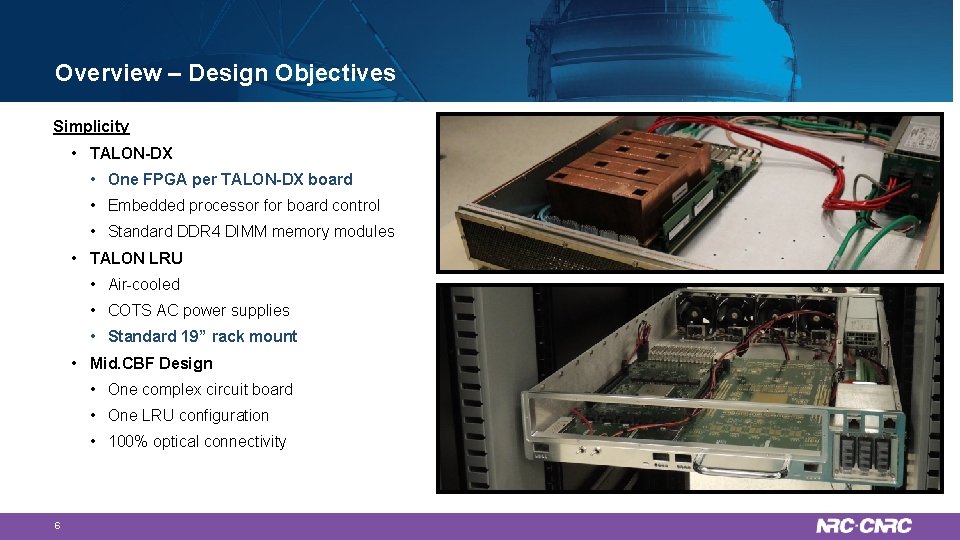
Overview – Design Objectives Simplicity • TALON-DX • One FPGA per TALON-DX board • Embedded processor for board control • Standard DDR 4 DIMM memory modules • TALON LRU • Air-cooled • COTS AC power supplies • Standard 19” rack mount • Mid. CBF Design • One complex circuit board • One LRU configuration • 100% optical connectivity 6
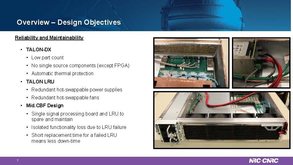
Overview – Design Objectives Reliability and Maintainability • TALON-DX • Low part count • No single source components (except FPGA) • Automatic thermal protection • TALON LRU • Redundant hot-swappable power supplies • Redundant hot-swappable fans • Mid. CBF Design • Single signal processing board and LRU to spare and maintain • Isolated functionality loss due to LRU failure • Short replacement time for a failed LRU means less down-time 7
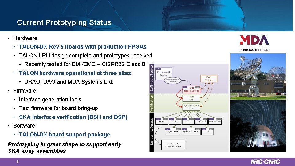
Current Prototyping Status • Hardware: • TALON-DX Rev 5 boards with production FPGAs • TALON LRU design complete and prototypes received • Recently tested for EMI/EMC – CISPR 32 Class B • TALON hardware operational at three sites: • DRAO, DAO and MDA Systems Ltd. • Firmware: • Interface generation tools • Test firmware for board bring-up • SKA Interface verification (DSH and DSP) • Software: • TALON-DX board support package Prototyping in great shape to support early SKA array assemblies 8
Planned and Potential Applications • Planned Applications: • SKA CSP Mid Correlator / Beamformer (Mid. CBF) Design • SKA DSH Single Pixel Feed Receiver (SPFRx) Design • ng. VLA Correlator / Beamformer Reference Design • ALMA Correlator Upgrade Study • ARTTA-4 – DRAO Synthesis Telescope Upgrade • Potential Applications: • CHIME follow-on projects • Interferometry image processing • Pulsar search and timing • Machine learning • Practically anything that requires high bandwidth computation 9
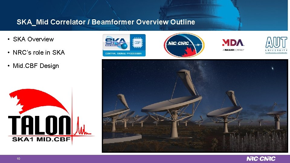
SKA_Mid Correlator / Beamformer Overview Outline • SKA Overview • NRC’s role in SKA • Mid. CBF Design 10
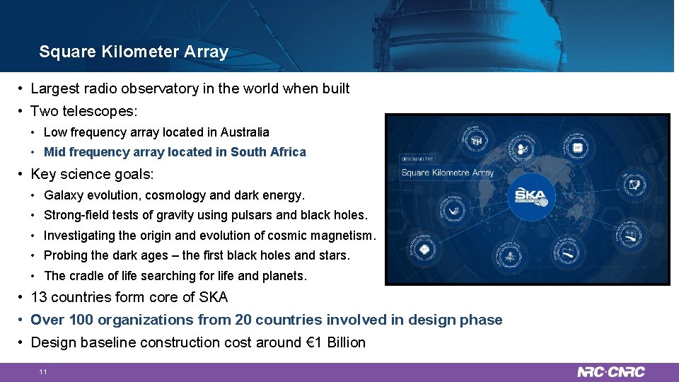
Square Kilometer Array • Largest radio observatory in the world when built • Two telescopes: • Low frequency array located in Australia • Mid frequency array located in South Africa • Key science goals: • Galaxy evolution, cosmology and dark energy. • Strong-field tests of gravity using pulsars and black holes. • Investigating the origin and evolution of cosmic magnetism. • Probing the dark ages – the first black holes and stars. • The cradle of life searching for life and planets. • 13 countries form core of SKA • Over 100 organizations from 20 countries involved in design phase • Design baseline construction cost around € 1 Billion 11

NRC and the SKA • Central Signal Processor Consortium leadership (Mid and Low) • Central Signal Processor Element project management (Mid and Low) and system engineering (Mid). • CSP Mid Correlator/Beamformer Sub-Element • DSH Single Pixel Feed Receiver 12
Mid. CBF Key Requirements / Functional Overview • Receive dual-pol’n digitized receptor data from DSH (197 receptors) • • Generate correlation visibility set and transmit to SDP • • • ~300 MHz bandwidth per beam Full stokes parameter output with min integration time of 64 us Generate 16 Pulsar Timing Beams • • • 13 Minimum 52 k channels per Band (many more possible) Instantaneous correlated bandwidth of 5 GHz per pol’n Minimum integration time of 0. 14 seconds Output bandwidth limited by links to SDP @ 6. 4 Tbps Generate 1500 Pulsar Search Beams • • • 96 Gbps per receptor in Band 1, 2, 4 & 5 (~19 Tbps total input) Up to 2. 5 GHz bandwidth per polarization Over-sampled channelization to facilitate BW reconstruction High fidelity polarization correction Generate full bandwidth VLBI beams + visibility set Capture a 62 second / 300 MHz transient buffer for each receptor Handle 16 independent sub-arrays Keep cost, power and rack space to a minimum
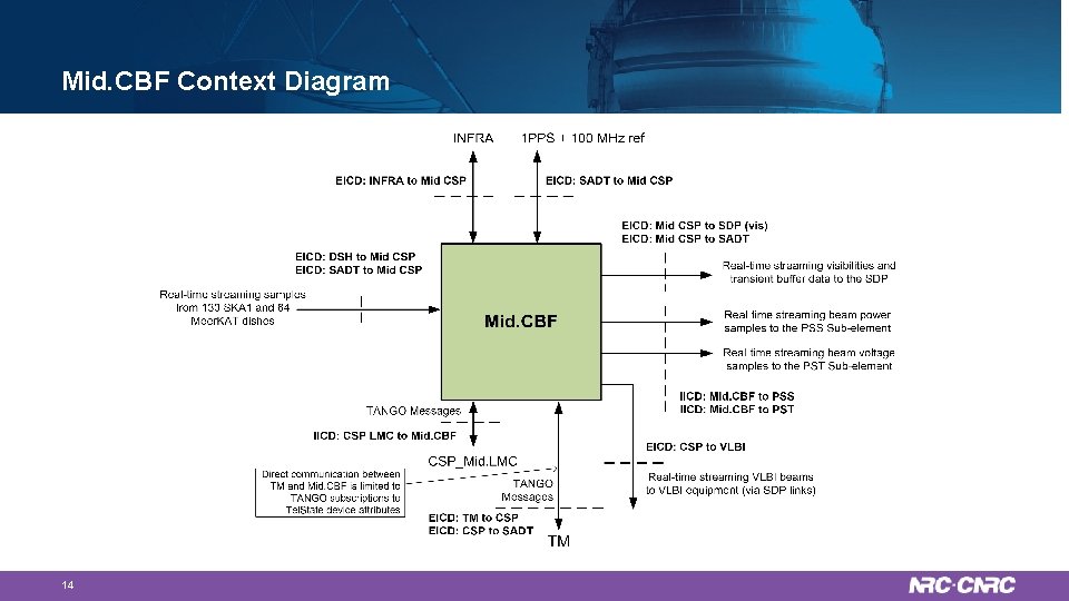
Mid. CBF Context Diagram 14
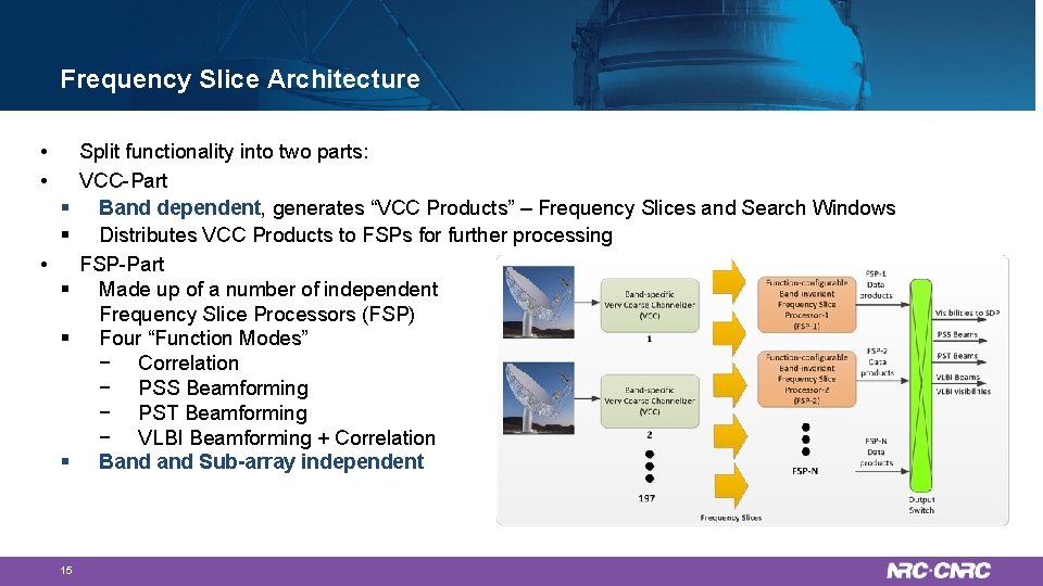
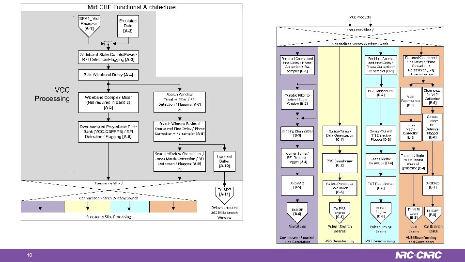
Frequency Slice Architecture • • § § § 15 Split functionality into two parts: VCC-Part Band dependent, generates “VCC Products” – Frequency Slices and Search Windows Distributes VCC Products to FSPs for further processing FSP-Part Made up of a number of independent Frequency Slice Processors (FSP) Four “Function Modes” − Correlation − PSS Beamforming − PST Beamforming − VLBI Beamforming + Correlation Band Sub-array independent
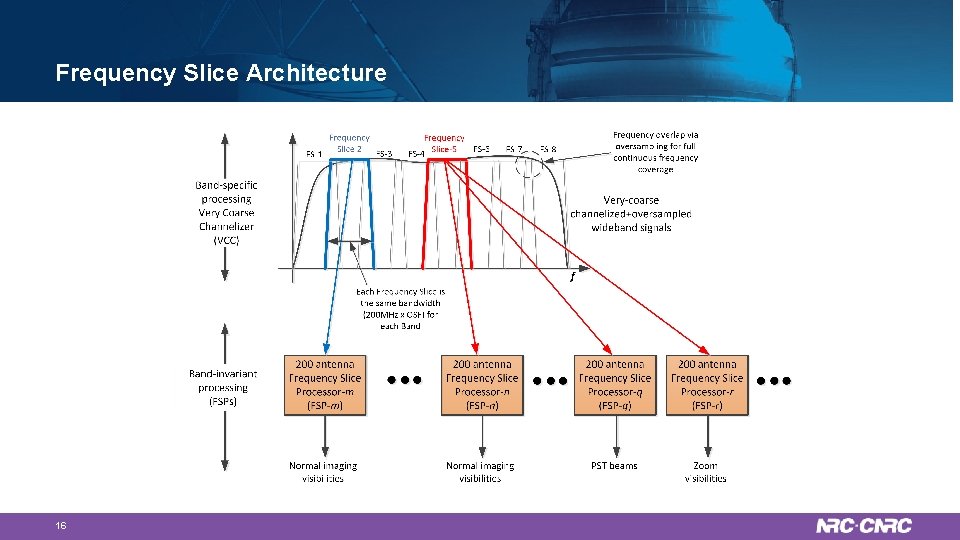
Frequency Slice Architecture 16
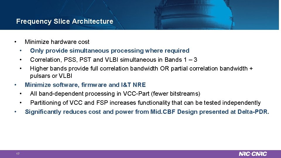
Frequency Slice Architecture • • 17 Minimize hardware cost Only provide simultaneous processing where required Correlation, PSS, PST and VLBI simultaneous in Bands 1 – 3 Higher bands provide full correlation bandwidth OR partial correlation bandwidth + pulsars or VLBI Minimize software, firmware and I&T NRE All band-dependent processing in VCC-Part (fewer bitstreams) Partitioning of VCC and FSP increases functionality that can be tested independently Significantly reduces cost and power from Mid. CBF Design presented at Delta-PDR.
18
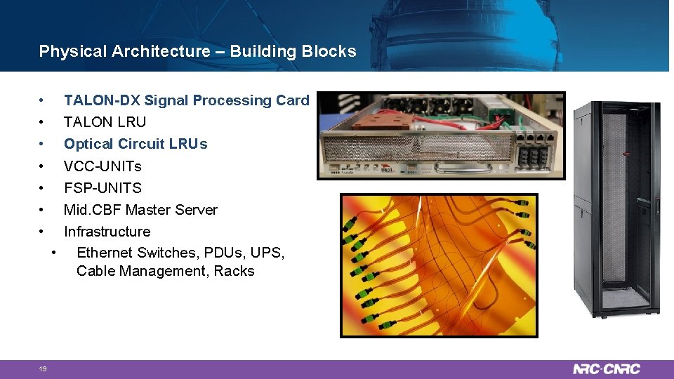
Physical Architecture – Building Blocks • • 19 TALON-DX Signal Processing Card TALON LRU Optical Circuit LRUs VCC-UNITs FSP-UNITS Mid. CBF Master Server Infrastructure • Ethernet Switches, PDUs, UPS, Cable Management, Racks
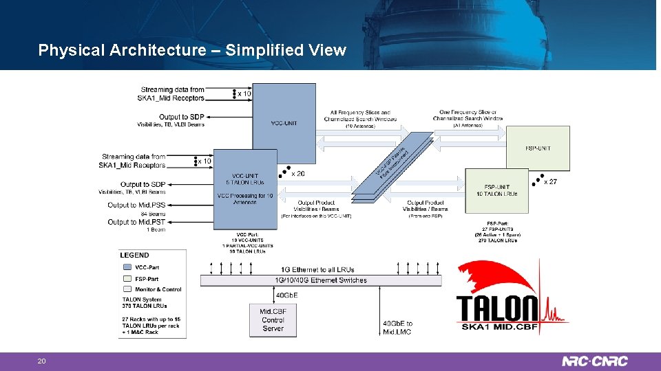
Physical Architecture – Simplified View 20
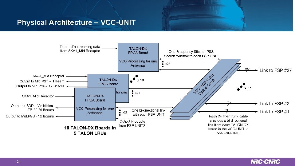
Physical Architecture – VCC-UNIT 21
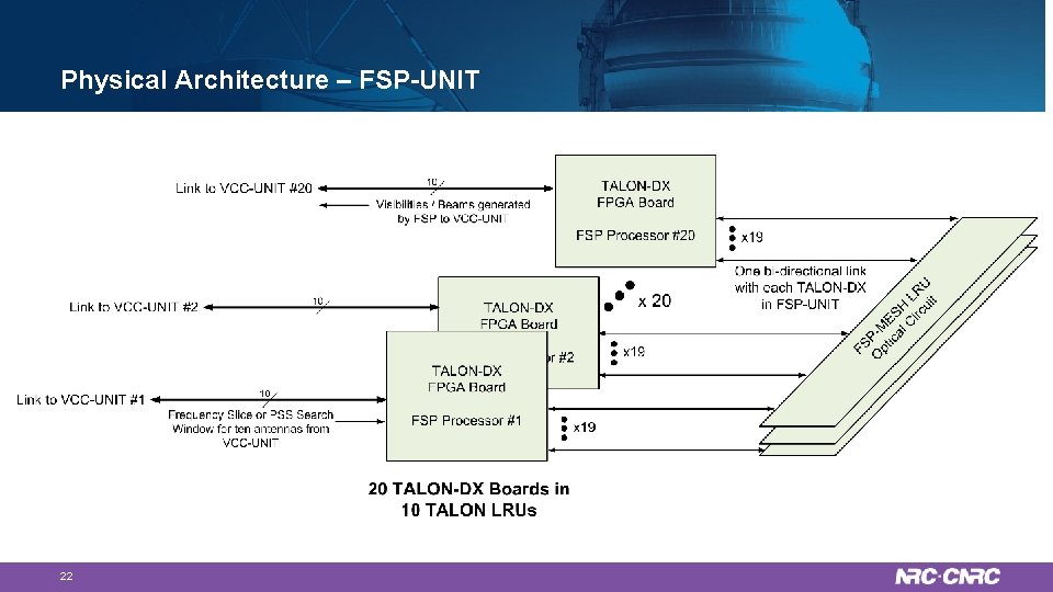
Physical Architecture – FSP-UNIT 22
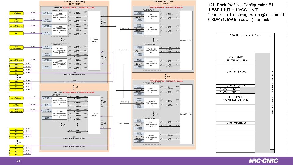
Physical Architecture 23
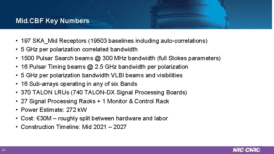
Mid. CBF Key Numbers • • • 24 197 SKA_Mid Receptors (19503 baselines including auto-correlations) 5 GHz per polarization correlated bandwidth 1500 Pulsar Search beams @ 300 MHz bandwidth (full Stokes parameters) 16 Pulsar Timing beams @ 2. 5 GHz bandwidth per polarization 5 GHz per polarization bandwidth VLBI beams and visibilities 16 Sub-arrays operating in any of six Bands 370 TALON LRUs (740 TALON-DX Signal Processing Boards) 27 Signal Processing Racks + 1 Monitor & Control Rack Power Estimate: 272 k. W Cost: € 30 M – roughly split between hardware and labor Construction Timeline: Mid 2021 – 2027 24
Thank you Mike Pleasance Project Engineer / Manager – HAA-ATD Digital Signal Processing Tel: 250 -497 -2346 Michael. Pleasance@nrc-cnrc. gc. ca www. nrc-cnrc. gc. ca 25 25
- Slides: 25