Systems PHAK 6 2 Landing Gear Tricycle l


 l Fixed l Retractable l PHAK 7 -33")


 Battery (normally")


- Slides: 44
Systems
PHAK 6 -2+
Landing Gear Tricycle l Conventional (Tailwheel) l Fixed l Retractable l PHAK 7 -33
Landing Gear l Spring steel struts – Strong & flexible – May be metal or composites – Simple & lightweight l Bungee Cords – mostly older or lightweight aircraft l Shock struts (Oleo struts) – An enclosed cylinder which houses a piston filled with air & oil
Bungee Cord Gear
Brakes l Disc type PHAK 7 -34
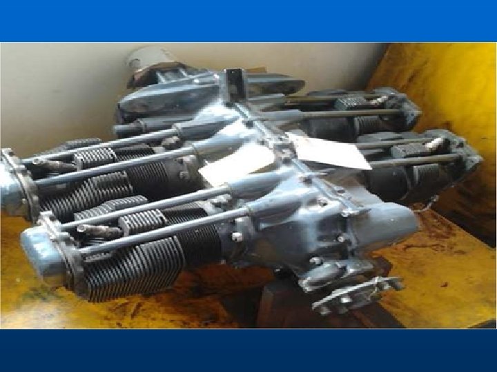
Powerplant l Designations – – – – l O—opposed cylinders I—injected T—turbocharged S—supercharged G—geared L—left turning V—cylinders in V formation GTSIO-520 (Cessna 421) PHAK 7 -22
Four-stroke Cycle
Oil Systems l Dry-sump – Oil is contained in a separate tank & circulated by pumps l Wet-sump – Oil is carried in a sump which is an integral part of the engine – Most common on small, reciprocating engines – Oil pump draws oil from the sump & routes it to the engine. It passes through the engine & returns to the sump l High oil temp may be caused by low oil level
Engine Cooling
Heating System
Carburetor PHAK 7 -8
Carburetor Icing Expect ice when temperatures are at or below 21°C or 70°F and the relative humidity is high, 50% or above First indication of carb ice is a loss of rpm in an aircraft with a fixed pitch prop
Carburetor Heat Use of Carb Heat generally decreases engine performance • Enriches the fuel/air mixture • Decrease engine output • Increases operating temps • Left on during takeoff will increase ground roll
Fuel Injection Systems PHAK 7 -11
EGT Gauges
Turbocharging PHAK 7 -12 l Max horsepower is determined by engine rpm & density of the intake air l Turbocharging compresses the intake air to increase density l Allows you to fly at higher altitudes and avoid adverse weather
System Operation l Waste gate position may be controlled by throttle or manually l Overboost—when the manifold pressure exceeds the engine’s limitations – Advance throttle slowly on takeoff and watch manifold pressure l Allow the turbocharger time to cool down before shutting the engine down, otherwise hard carbon deposits may form on bearings and shaft l May use the TIT(Turbine Inlet Temperature) gauge for leaning instead of the EGT
Turbocharging
Ignition Systems l PHAK 7 -15 Engine ignition provided by magnetos – Mags generate their own electricity by selfcontained magnets – Dual mags provide improved combustion, performance, & safety – When the engine runs after ignition switch turned off then you probably have a broken ground wire (P lead) • Can check this by idling the engine prior to shutdown & quickly turning off the ignition
Ignition System
Magneto
Magnetos
Abnormal Combustion Detonation & Preignition – Detonation occurs when the unburned fuel/air charge instantaneously combusts • May be caused by low fuel grade or high engine temp • If suspected reduce throttle, lower nose, & enrich mixture for improved cooling – Preignition is the uncontrolled firing of the fuel/ air charge prior to normal ignition • May be caused by an area roughened or heated by detonation
PHAK 7 -25 Fuel Systems Gravity feed Filling the tanks after the last flight of the day prevents moisture from condensing
Fuel Systems Fuel pump • Running a tank dry may cause vapor lock
Fuel • Contamination • Inadequate preflight • Using fuel from unfiltered tanks • Poor maintenance • Fuel Grades
Constant-Speed Props l Allows you to obtain the best combination of engine rpm & MP for the operation – Climb prop and a cruise prop together – A fixed-pitch prop is designed for best efficiency only at a given airspeed and rpm l A CS prop allows you to select the blade angle that provides the most efficient performance
CS Prop Operation l A governor automatically adjusts blade angle to maintain a certain rpm l With a constant speed prop, the throttle controls engine power output, as indicated on the manifold pressure gauge, while the propeller control regulates engine rpm
CS Prop Operation l Use high RPM, low blade angle, for takeoff – Generates maximum thrust l Avoid high manifold pressure settings with low RPM l When changing power or rpm settings: – Increase rpm before throttle – Decrease throttle before rpm – This helps to prevent exceeding normal MP
Basic Oxygen System
Oxygen Systems l Cylinders – – l Most popular Usually painted green Should say “Aviators Breathing Oxygen” (99. 5%) Can be mounted or portable Generators – Often used in pressurized cabins – Above FL 250 must have 10 minutes of O for each occupant – Can only be used once
FAA Oxygen Regs Oxygen required from 12, 500’ to 14, 000’ for that part of the flight that is more than 30 min duration l Above 14, 000’ required for the minimum flight crew l Above 15, 000’ must be provided for all occupants l
Electrical System l Components – – Alternator (normally 14 or 28 volt) Battery (normally 12 or 24 volt) Ammeter Master switch • Avionics master – Circuit breakers & fuses • Fuses—one spare set or 3 of each kind
• An AMMETER shows if the alternator/generator is producing an adequate supply of electrical power • When the pointer of the ammeter is on the plus side, it shows the charging rate of the battery • A minus indication means more current is being drawn from the battery than is being replaced • A full-scale minus deflection indicates a malfunction of the alternator/generator • A full-scale positive deflection indicates a malfunction of the regulator • The LOADMETER reflects the total percentage of the load placed on the generating capacity of the electrical system by the electrical accessories and battery • When all electrical components are turned off, it reflects only the amount of charging current demanded by the battery
Electrical System Schematic
Ice Control Systems l Airfoil Ice Control – De-ice boots – Thermal anti-ice l Windshield Ice Control – Anti-ice: alcohol or electric heat l Prop Ice Control – Anti-ice: alcohol or electric heat Pitot Heat l Fuel vent heat l Stall-warning heat l
De-ice boots
Gleim Questions l Sections 2. 10 -2. 20