
Systems Analysis Development for ARIES Next Step C
- Slides: 18
Systems Analysis Development for ARIES Next Step C. E. Kessel 1, Z. Dragojlovic 2, and R. Raffrey 2 1 Princeton Plasma Physics Laboratory 2 University of California, San Diego ARIES Next Step Meeting, April 3 -4, 2007, UCSD
Motivation for a “New” Systems Code • Systems codes are critical tools in fusion design, because they integrate physics, engineering, design and costing – Scanning can be done with simple models – Results from detailed analysis can be incorporated for more specific searches • Our ARIES Systems Code (ASC) has become very cumbersome and has lost its technical maintenance (primarily physics and engineering) • The approach taken by most (if not all) systems codes has been to produce an optimal operating point, which is often difficult to justify, why is it optimal? • This does not utilize the power of a systems code, which is to generate many operating points (operating space approach)
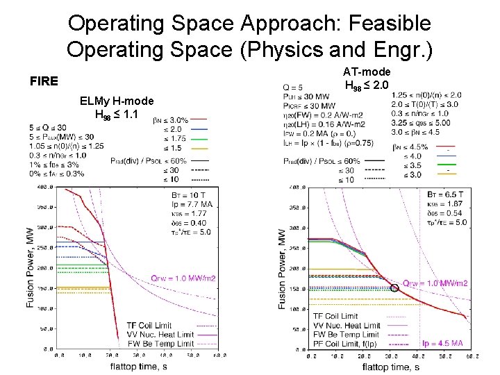
Operating Space Approach to Systems Analysis • On the FIRE project I developed a systems code that combined physics and engineering analysis for a burning plasma experiment, which found the minimum major radius solution within several constraints • For Snowmass 2002 I took the physics part out, and began to use it to generate many physics operating points, that satisfied multiple physics boundaries/constraints ---> physics operating space • Finally I started to use a second code that took the all the viable physics operating points and imposed engineering constraints (divertor heat load, FW surface heat load, nuclear heating, TF coil heating, PF coil heating, etc) and physics filters to find feasible operating space
Operating Space Approach: Feasible Operating Space (Physics and Engr. ) AT-mode H 98 ≤ 2. 0 FIRE ELMy H-mode H 98 ≤ 1. 1
The Operating Space Approach Has Several Advantages • Operating space approach to systems analysis makes the effect of constraints more transparent • Many constraints carry a lot of uncertainty, which can be quantified • Sequencing the analysis through 1) physics operating space, 2) engineering operating space, and 3) device build and cost, will provide a better explanation of available operating points and why they are desirable
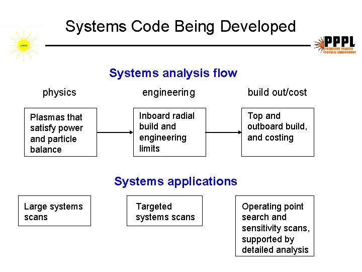
Systems Code Being Developed Systems analysis flow physics Plasmas that satisfy power and particle balance engineering build out/cost Inboard radial build and engineering limits Top and outboard build, and costing Systems applications Large systems scans Targeted systems scans Operating point search and sensitivity scans, supported by detailed analysis
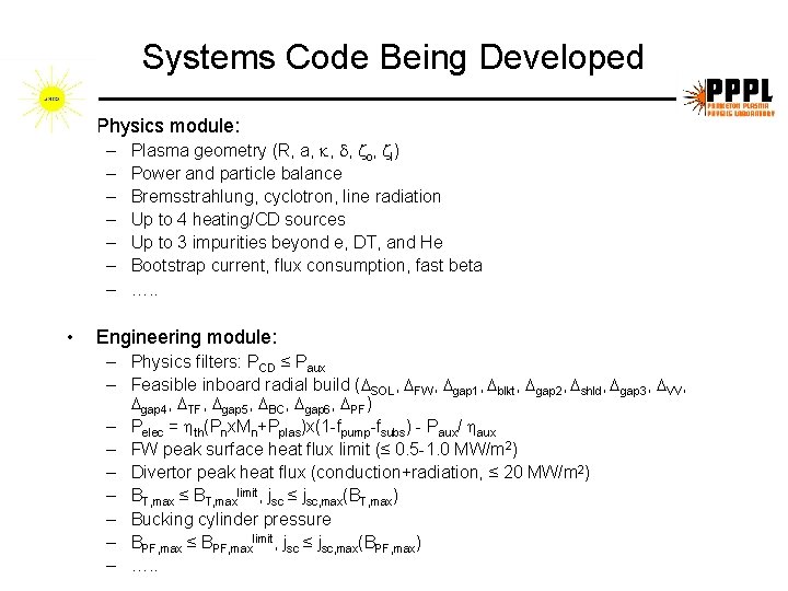
Systems Code Being Developed • Physics module: – – – – • Plasma geometry (R, a, , , o, I) Power and particle balance Bremsstrahlung, cyclotron, line radiation Up to 4 heating/CD sources Up to 3 impurities beyond e, DT, and He Bootstrap current, flux consumption, fast beta …. . Engineering module: – Physics filters: PCD ≤ Paux – Feasible inboard radial build ( SOL, FW, gap 1, blkt, gap 2, shld, gap 3, VV, gap 4, TF, gap 5, BC, gap 6, PF) – Pelec = th(Pnx. Mn+Pplas)x(1 -fpump-fsubs) - Paux/ aux – FW peak surface heat flux limit (≤ 0. 5 -1. 0 MW/m 2) – Divertor peak heat flux (conduction+radiation, ≤ 20 MW/m 2) – BT, max ≤ BT, maxlimit, jsc ≤ jsc, max(BT, max) – Bucking cylinder pressure – BPF, max ≤ BPF, maxlimit, jsc ≤ jsc, max(BPF, max) – …. .
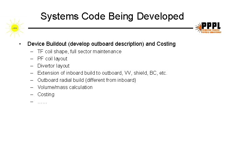
Systems Code Being Developed • Device Buildout (develop outboard description) and Costing – – – – TF coil shape, full sector maintenance PF coil layout Divertor layout Extension of inboard build to outboard, VV, shield, BC, etc. Outboard radial build (different from inboard) Volume/mass calculation Costing ……
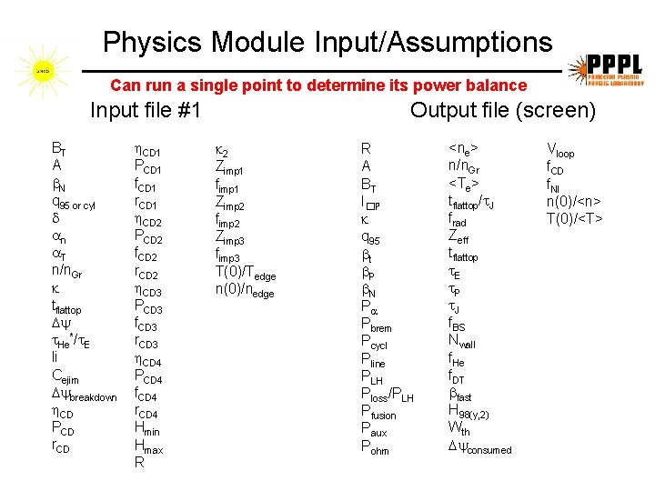
Physics Module Input/Assumptions Can run a single point to determine its power balance Input file #1 BT A N q 95 or cyl n T n/n. Gr tflattop He*/ E li Cejim breakdown CD PCD r. CD 1 PCD 1 f. CD 1 r. CD 1 CD 2 PCD 2 f. CD 2 r. CD 2 CD 3 PCD 3 f. CD 3 r. CD 3 CD 4 PCD 4 f. CD 4 r. CD 4 Hmin Hmax R Output file (screen) 2 Zimp 1 fimp 1 Zimp 2 fimp 2 Zimp 3 fimp 3 T(0)/Tedge n(0)/nedge R A BT I�P q 95 t P N P Pbrem Pcycl Pline PLH Ploss/PLH Pfusion Paux Pohm <ne> n/n. Gr <Te> tflattop/ J frad Zeff tflattop E P J f. BS Nwall f. He f. DT fast H 98(y, 2) Wth consumed Vloop f. CD f. NI n(0)/<n> T(0)/<T>
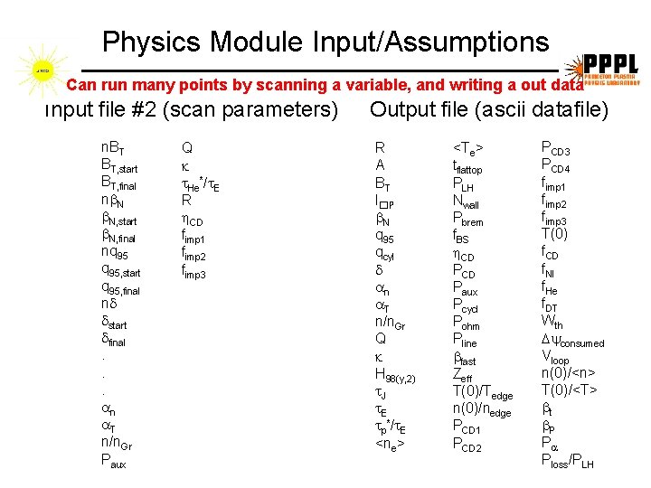
Physics Module Input/Assumptions Can run many points by scanning a variable, and writing a out data Input file #2 (scan parameters) n. BT BT, start BT, final n N N, start N, final nq 95, start q 95, final n start final. . . n T n/n. Gr Paux Q He*/ E R CD fimp 1 fimp 2 fimp 3 Output file (ascii datafile) R A BT I�P N q 95 qcyl n T n/n. Gr Q H 98(y, 2) J E p*/ E <ne> <Te> tflattop PLH Nwall Pbrem f. BS CD Paux Pcycl Pohm Pline fast Zeff T(0)/Tedge n(0)/nedge PCD 1 PCD 2 PCD 3 PCD 4 fimp 1 fimp 2 fimp 3 T(0) f. CD f. NI f. He f. DT Wth consumed Vloop n(0)/<n> T(0)/<T> t P P Ploss/PLH
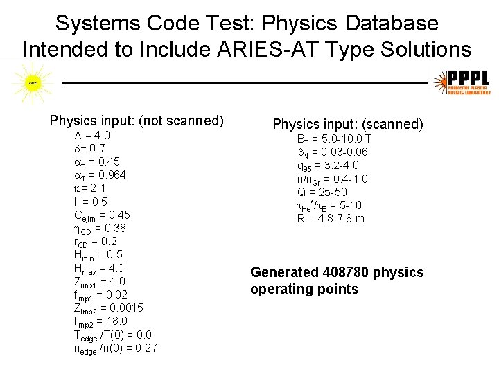
Systems Code Test: Physics Database Intended to Include ARIES-AT Type Solutions Physics input: (not scanned) A = 4. 0 = 0. 7 n = 0. 45 T = 0. 964 = 2. 1 li = 0. 5 Cejim = 0. 45 CD = 0. 38 r. CD = 0. 2 Hmin = 0. 5 Hmax = 4. 0 Zimp 1 = 4. 0 fimp 1 = 0. 02 Zimp 2 = 0. 0015 fimp 2 = 18. 0 Tedge /T(0) = 0. 0 nedge /n(0) = 0. 27 Physics input: (scanned) BT = 5. 0 -10. 0 T N = 0. 03 -0. 06 q 95 = 3. 2 -4. 0 n/n. Gr = 0. 4 -1. 0 Q = 25 -50 He*/ E = 5 -10 R = 4. 8 -7. 8 m Generated 408780 physics operating points
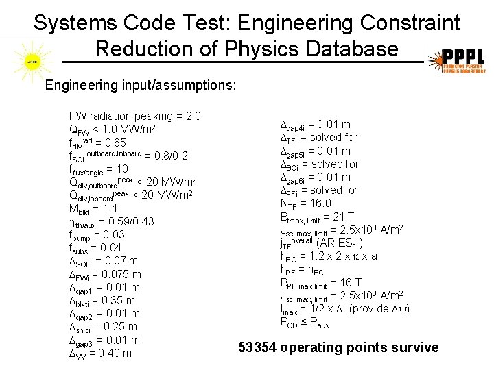
Systems Code Test: Engineering Constraint Reduction of Physics Database Engineering input/assumptions: FW radiation peaking = 2. 0 QFW < 1. 0 MW/m 2 fdivrad = 0. 65 f. SOLoutboard/inboard = 0. 8/0. 2 fflux/angle = 10 Qdiv, outboardpeak < 20 MW/m 2 Qdiv, inboardpeak < 20 MW/m 2 Mblkt = 1. 1 th/aux = 0. 59/0. 43 fpump = 0. 03 fsubs = 0. 04 SOLi = 0. 07 m FWi = 0. 075 m gap 1 i = 0. 01 m blkti = 0. 35 m gap 2 i = 0. 01 m shldi = 0. 25 m gap 3 i = 0. 01 m VV = 0. 40 m gap 4 i = 0. 01 m TFi = solved for gap 5 i = 0. 01 m BCi = solved for gap 6 i = 0. 01 m PFi = solved for NTF = 16. 0 Btmax, limit = 21 T Jsc, max, limit = 2. 5 x 10⁸ A/m 2 j. TFoverall (ARIES-I) h. BC = 1. 2 x x a h. PF = h. BC BPF, max, limit = 16 T Jsc, max, limit = 2. 5 x 10⁸ A/m 2 Imax = 1/2 x I (provide ) PCD ≤ Paux 53354 operating points survive
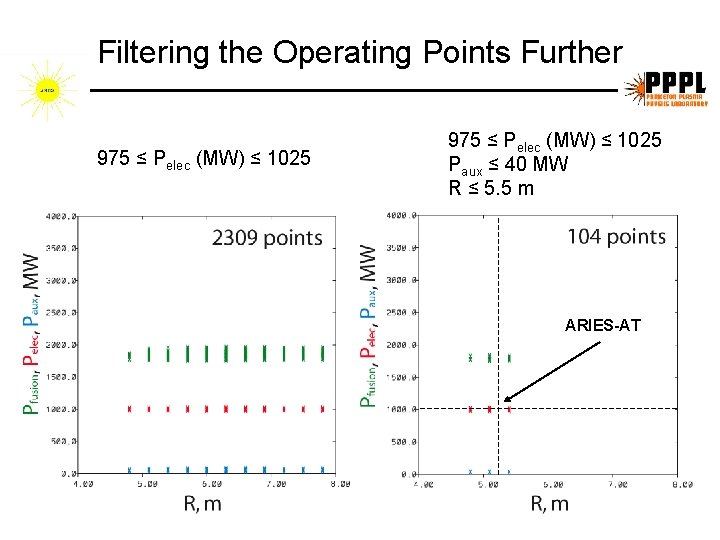
Filtering the Operating Points Further 975 ≤ Pelec (MW) ≤ 1025 Paux ≤ 40 MW R ≤ 5. 5 m ARIES-AT
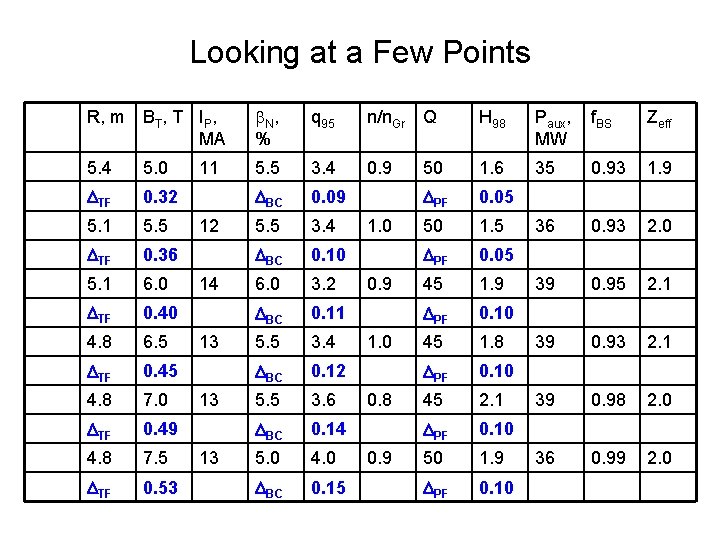
Looking at a Few Points R, m BT, T IP, MA N , % q 95 n/n. Gr Q H 98 Paux, MW f. BS Zeff 5. 4 5. 0 5. 5 3. 4 0. 9 50 1. 6 35 0. 93 1. 9 TF 0. 32 BC 0. 09 PF 0. 05 5. 1 5. 5 3. 4 50 1. 5 36 0. 93 2. 0 TF 0. 36 BC 0. 10 PF 0. 05 5. 1 6. 0 3. 2 45 1. 9 39 0. 95 2. 1 TF 0. 40 BC 0. 11 PF 0. 10 4. 8 6. 5 5. 5 3. 4 45 1. 8 39 0. 93 2. 1 TF 0. 45 BC 0. 12 PF 0. 10 4. 8 7. 0 5. 5 3. 6 45 2. 1 39 0. 98 2. 0 TF 0. 49 BC 0. 14 PF 0. 10 4. 8 7. 5 5. 0 4. 0 50 1. 9 36 0. 99 2. 0 TF 0. 53 BC 0. 15 PF 0. 10 11 12 14 13 13 13 1. 0 0. 9 1. 0 0. 8 0. 9
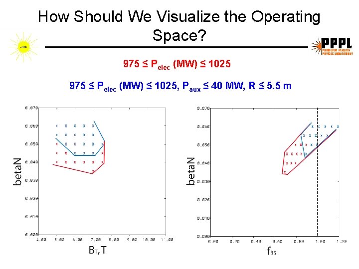
How Should We Visualize the Operating Space? 975 ≤ Pelec (MW) ≤ 1025, Paux ≤ 40 MW, R ≤ 5. 5 m
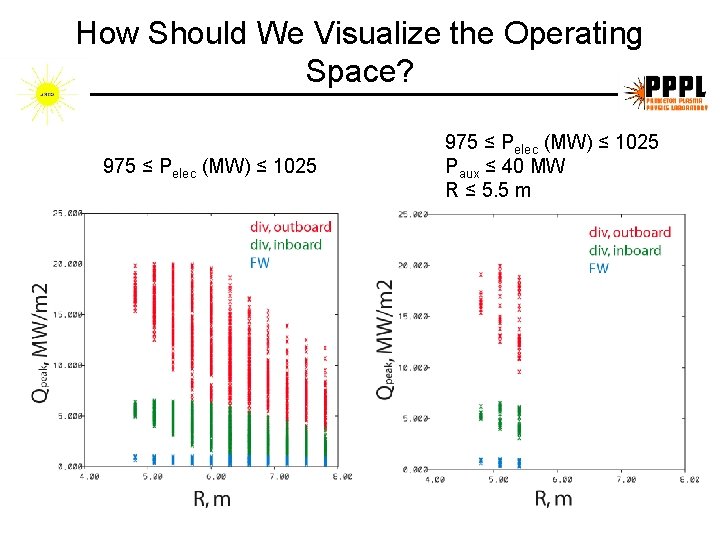
How Should We Visualize the Operating Space? 975 ≤ Pelec (MW) ≤ 1025 Paux ≤ 40 MW R ≤ 5. 5 m
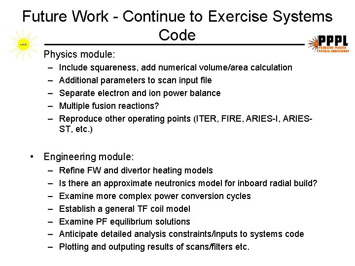
Future Work - Continue to Exercise Systems Code • Physics module: – – – Include squareness, add numerical volume/area calculation Additional parameters to scan input file Separate electron and ion power balance Multiple fusion reactions? Reproduce other operating points (ITER, FIRE, ARIES-I, ARIESST, etc. ) • Engineering module: – – – – Refine FW and divertor heating models Is there an approximate neutronics model for inboard radial build? Examine more complex power conversion cycles Establish a general TF coil model Examine PF equilibrium solutions Anticipate detailed analysis constraints/inputs to systems code Plotting and outputing results of scans/filters etc.
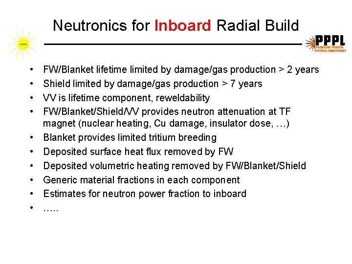
Neutronics for Inboard Radial Build • • • FW/Blanket lifetime limited by damage/gas production > 2 years Shield limited by damage/gas production > 7 years VV is lifetime component, reweldability FW/Blanket/Shield/VV provides neutron attenuation at TF magnet (nuclear heating, Cu damage, insulator dose, …) Blanket provides limited tritium breeding Deposited surface heat flux removed by FW Deposited volumetric heating removed by FW/Blanket/Shield Generic material fractions in each component Estimates for neutron power fraction to inboard …. .