
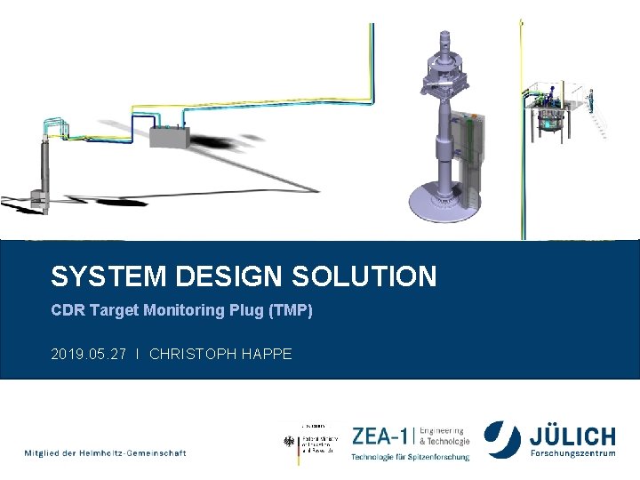
SYSTEM DESIGN SOLUTION CDR Target Monitoring Plug TMP

- Slides: 40
SYSTEM DESIGN SOLUTION CDR Target Monitoring Plug (TMP) 2019. 05. 27 I CHRISTOPH HAPPE
OUTLINE ESS – Target Monitoring Plug – System Design Solution 1. Target Monitoring Plug System Overview & Description 2. Overview of main body assembly 3. Overview functional group 100 (XY-measurement) 4. Overview functional group 200 (Z-measurement Insert) 5. Overview functional group 300 (IR-measurement Insert) 6. Interface Description 7. Documentation example Page 2
OUTLINE ESS – Target Monitoring Plug – System Design Solution 1. Target Monitoring Plug System Overview & Description 2. Overview of main body assembly 3. Overview functional group 100 (XY-measurement) 4. Overview functional group 200 (Z-measurement Insert) 5. Overview functional group 300 (IR-measurement Insert) 6. Interface Description 7. Documentation example Page 3
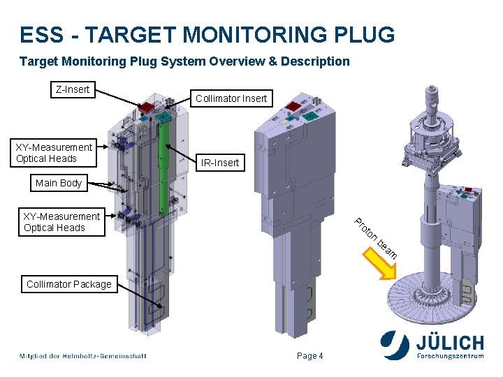
ESS - TARGET MONITORING PLUG Target Monitoring Plug System Overview & Description Z-Insert XY-Measurement Optical Heads Collimator Insert IR-Insert Main Body XY-Measurement Optical Heads Pr ot on Collimator Package Page 4 be am
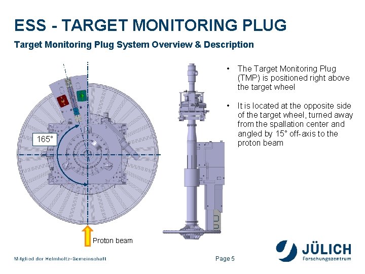
ESS - TARGET MONITORING PLUG Target Monitoring Plug System Overview & Description • The Target Monitoring Plug (TMP) is positioned right above the target wheel • It is located at the opposite side of the target wheel, turned away from the spallation center and angled by 15° off-axis to the proton beam 165° Proton beam Page 5
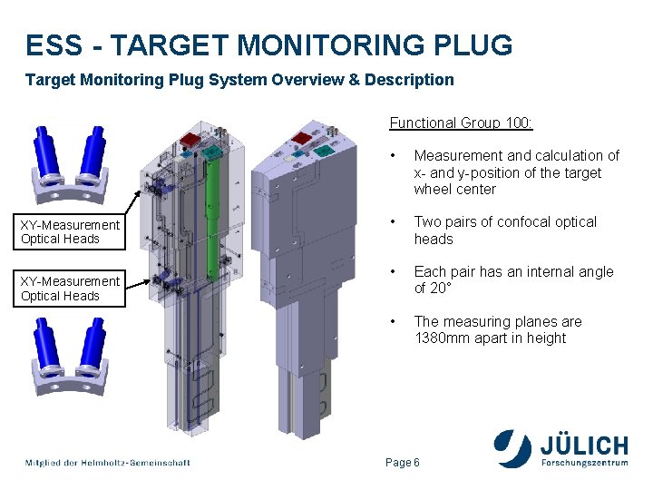
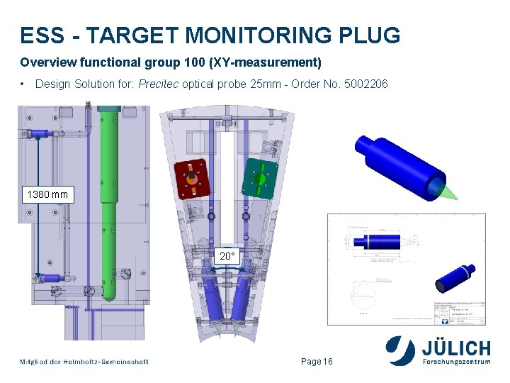
ESS - TARGET MONITORING PLUG Target Monitoring Plug System Overview & Description Functional Group 100: XY-Measurement Optical Heads • Measurement and calculation of x- and y-position of the target wheel center • Two pairs of confocal optical heads • Each pair has an internal angle of 20° • The measuring planes are 1380 mm apart in height Page 6
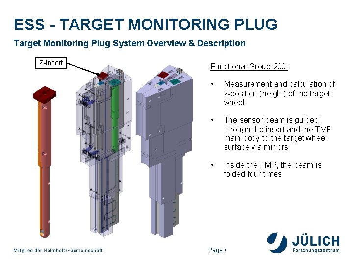
ESS - TARGET MONITORING PLUG Target Monitoring Plug System Overview & Description Z-Insert Functional Group 200: • Measurement and calculation of z-position (height) of the target wheel • The sensor beam is guided through the insert and the TMP main body to the target wheel surface via mirrors • Inside the TMP, the beam is folded four times Page 7
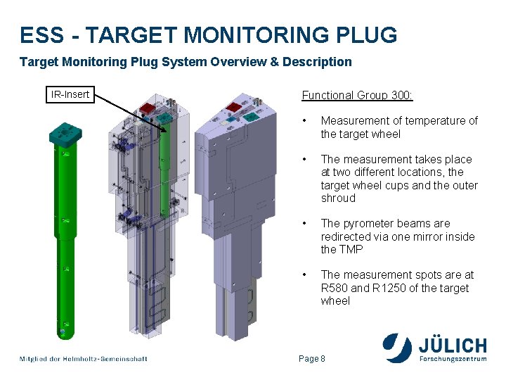
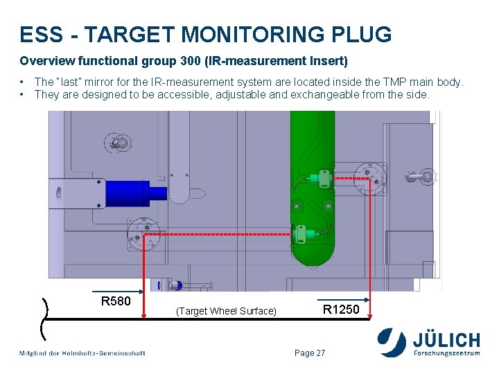
ESS - TARGET MONITORING PLUG Target Monitoring Plug System Overview & Description IR-Insert Functional Group 300: • Measurement of temperature of the target wheel • The measurement takes place at two different locations, the target wheel cups and the outer shroud • The pyrometer beams are redirected via one mirror inside the TMP • The measurement spots are at R 580 and R 1250 of the target wheel Page 8
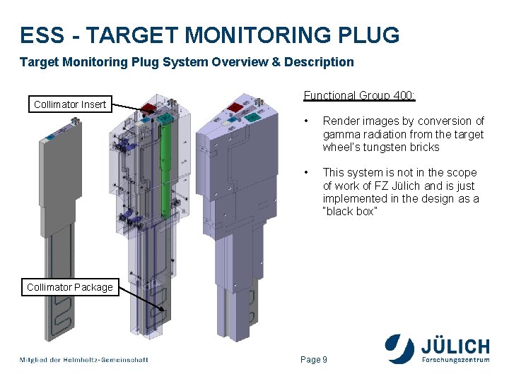
ESS - TARGET MONITORING PLUG Target Monitoring Plug System Overview & Description Collimator Insert Functional Group 400: • Render images by conversion of gamma radiation from the target wheel’s tungsten bricks • This system is not in the scope of work of FZ Jülich and is just implemented in the design as a “black box” Collimator Package Page 9
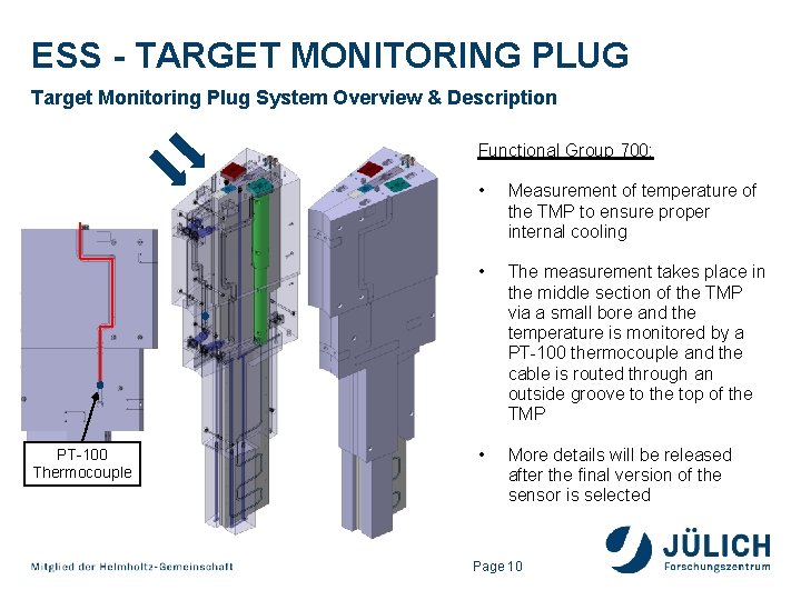
ESS - TARGET MONITORING PLUG Target Monitoring Plug System Overview & Description Functional Group 700: PT-100 Thermocouple • Measurement of temperature of the TMP to ensure proper internal cooling • The measurement takes place in the middle section of the TMP via a small bore and the temperature is monitored by a PT-100 thermocouple and the cable is routed through an outside groove to the top of the TMP • More details will be released after the final version of the sensor is selected Page 10
OUTLINE ESS – Target Monitoring Plug – System Design Solution 1. Target Monitoring Plug System Overview & Description 2. Overview of main body assembly 3. Overview functional group 100 (XY-measurement) 4. Overview functional group 200 (Z-measurement Insert) 5. Overview functional group 300 (IR-measurement Insert) 6. Interface Description 7. Documentation example Page 11
ESS - TARGET MONITORING PLUG Overview of main body assembly The main body consists of four individual parts, that are joined to one assembly. 1 8 26 72 2 1 Body Assembly (1. 4306): mtotal = 8667 kg 4 Component Parts: No. 1: 3922 • m 1 = 4084 kg 3140 x 361 x 1268 No. 2: m 2 = 4003 kg 3140 x 361 x 1268 No. 3: m 3 = 314 kg 922 x 184 x 290 No. 4: 2 3 m 4 = 266 kg 922 x 184 x 231 4 Page 12
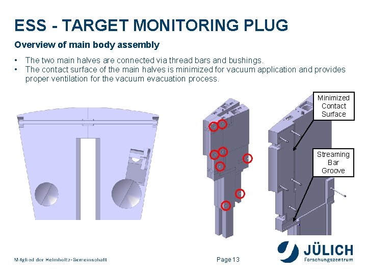
ESS - TARGET MONITORING PLUG Overview of main body assembly • • The two main halves are connected via thread bars and bushings. The contact surface of the main halves is minimized for vacuum application and provides proper ventilation for the vacuum evacuation process. Minimized Contact Surface Streaming Bar Groove Page 13
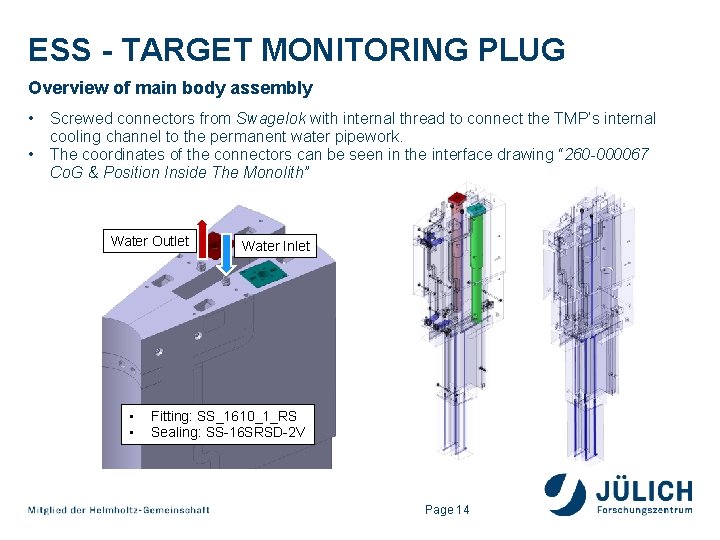
ESS - TARGET MONITORING PLUG Overview of main body assembly • • Screwed connectors from Swagelok with internal thread to connect the TMP’s internal cooling channel to the permanent water pipework. The coordinates of the connectors can be seen in the interface drawing “ 260 -000067 Co. G & Position Inside The Monolith” Water Outlet • • Water Inlet Fitting: SS_1610_1_RS Sealing: SS-16 SRSD-2 V Page 14
OUTLINE ESS – Target Monitoring Plug – System Design Solution 1. Target Monitoring Plug System Overview & Description 2. Overview of main body assembly 3. Overview functional group 100 (XY-measurement) 4. Overview functional group 200 (Z-measurement Insert) 5. Overview functional group 300 (IR-measurement Insert) 6. Interface Description 7. Documentation example Page 15
ESS - TARGET MONITORING PLUG Overview functional group 100 (XY-measurement) • Design Solution for: Precitec optical probe 25 mm - Order No. 5002206 1380 mm 20° Page 16
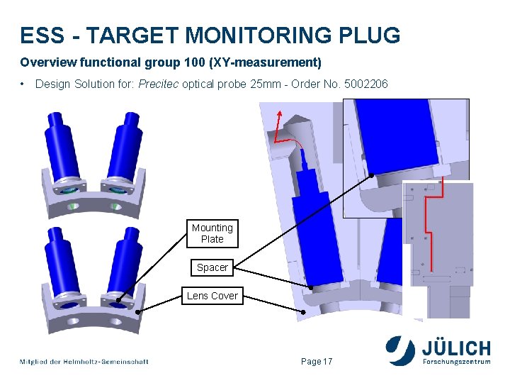
ESS - TARGET MONITORING PLUG Overview functional group 100 (XY-measurement) • Design Solution for: Precitec optical probe 25 mm - Order No. 5002206 Mounting Plate Spacer Lens Cover Page 17
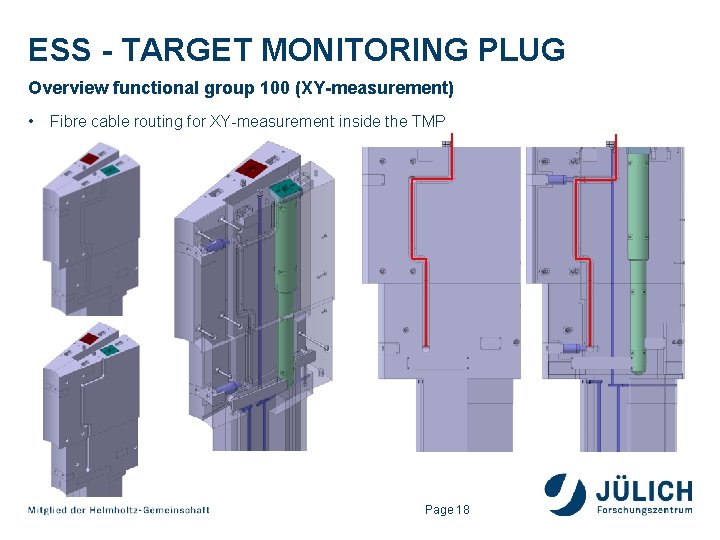
ESS - TARGET MONITORING PLUG Overview functional group 100 (XY-measurement) • Fibre cable routing for XY-measurement inside the TMP Page 18
OUTLINE ESS – Target Monitoring Plug – System Design Solution 1. Target Monitoring Plug System Overview & Description 2. Overview of main body assembly 3. Overview functional group 100 (XY-measurement) 4. Overview functional group 200 (Z-measurement Insert) 5. Overview functional group 300 (IR-measurement Insert) 6. Interface Description 7. Documentation example Page 19
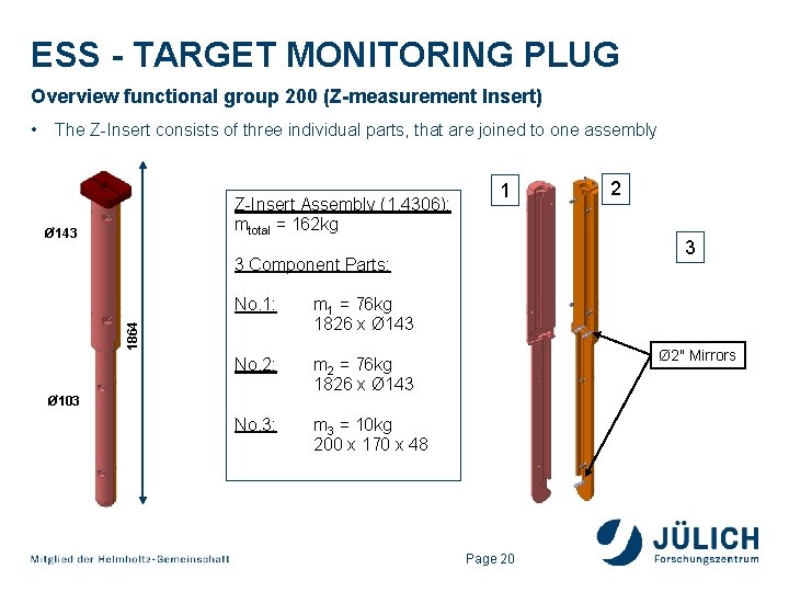
ESS - TARGET MONITORING PLUG Overview functional group 200 (Z-measurement Insert) The Z-Insert consists of three individual parts, that are joined to one assembly Z-Insert Assembly (1. 4306): mtotal = 162 kg Ø 143 1 No. 1: m 1 = 76 kg 1826 x Ø 143 No. 2: m 2 = 76 kg 1826 x Ø 143 No. 3: m 3 = 10 kg 200 x 170 x 48 Ø 103 2 3 3 Component Parts: 1864 • Ø 2" Mirrors Page 20
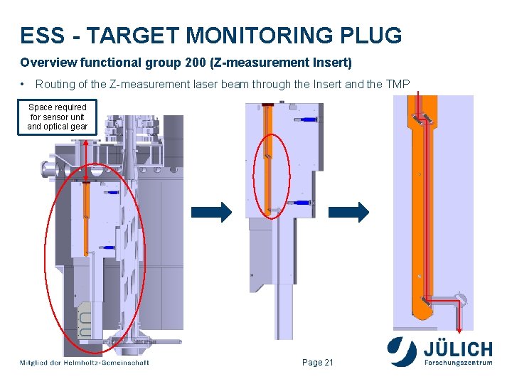
ESS - TARGET MONITORING PLUG Overview functional group 200 (Z-measurement Insert) • Routing of the Z-measurement laser beam through the Insert and the TMP Space required for sensor unit and optical gear Page 21
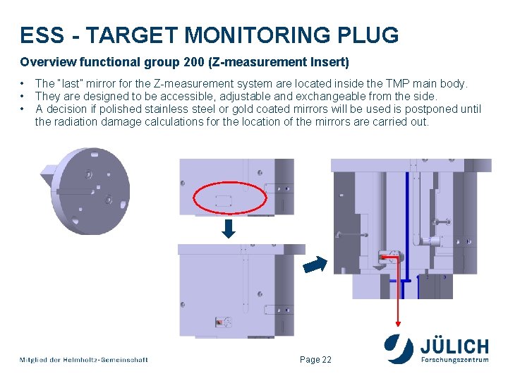
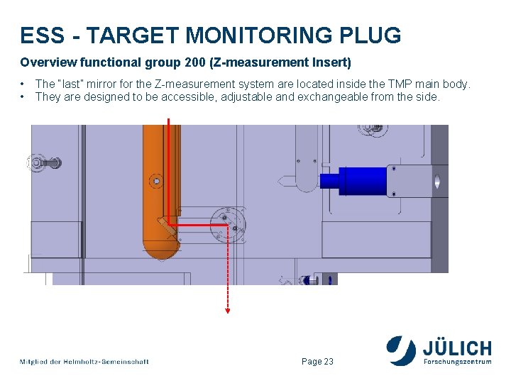
ESS - TARGET MONITORING PLUG Overview functional group 200 (Z-measurement Insert) • • • The “last” mirror for the Z-measurement system are located inside the TMP main body. They are designed to be accessible, adjustable and exchangeable from the side. A decision if polished stainless steel or gold coated mirrors will be used is postponed until the radiation damage calculations for the location of the mirrors are carried out. Page 22
ESS - TARGET MONITORING PLUG Overview functional group 200 (Z-measurement Insert) • • The “last” mirror for the Z-measurement system are located inside the TMP main body. They are designed to be accessible, adjustable and exchangeable from the side. Page 23
OUTLINE ESS – Target Monitoring Plug – System Design Solution 1. Target Monitoring Plug System Overview & Description 2. Overview of main body assembly 3. Overview functional group 100 (XY-measurement) 4. Overview functional group 200 (Z-measurement Insert) 5. Overview functional group 300 (IR-measurement Insert) 6. Interface Description 7. Documentation example Page 24
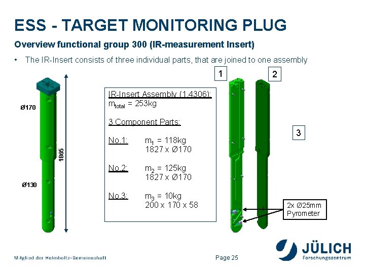
ESS - TARGET MONITORING PLUG Overview functional group 300 (IR-measurement Insert) The IR-Insert consists of three individual parts, that are joined to one assembly 1 2 IR-Insert Assembly (1. 4306): mtotal = 253 kg Ø 170 3 Component Parts: No. 1: m 1 = 118 kg 1827 x Ø 170 No. 2: m 2 = 125 kg 1827 x Ø 170 No. 3: m 3 = 10 kg 200 x 170 x 58 1865 • Ø 130 3 2 x Ø 25 mm Pyrometer Page 25
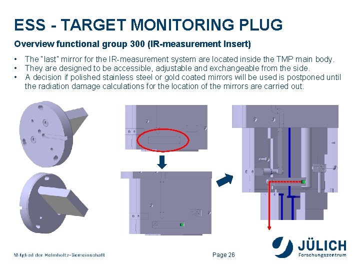
ESS - TARGET MONITORING PLUG Overview functional group 300 (IR-measurement Insert) • • • The “last” mirror for the IR-measurement system are located inside the TMP main body. They are designed to be accessible, adjustable and exchangeable from the side. A decision if polished stainless steel or gold coated mirrors will be used is postponed until the radiation damage calculations for the location of the mirrors are carried out. Page 26
ESS - TARGET MONITORING PLUG Overview functional group 300 (IR-measurement Insert) • • The “last” mirror for the IR-measurement system are located inside the TMP main body. They are designed to be accessible, adjustable and exchangeable from the side. R 580 (Target Wheel Surface) R 1250 Page 27
OUTLINE ESS – Target Monitoring Plug – System Design Solution 1. Target Monitoring Plug System Overview & Description 2. Overview of main body assembly 3. Overview functional group 100 (XY-measurement) 4. Overview functional group 200 (Z-measurement Insert) 5. Overview functional group 300 (IR-measurement Insert) 6. Interface Description 7. Documentation example Page 28
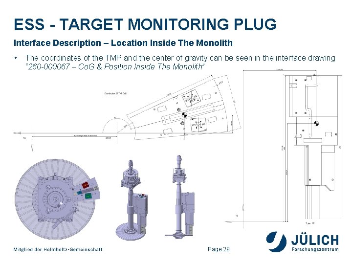
ESS - TARGET MONITORING PLUG Interface Description – Location Inside The Monolith • The coordinates of the TMP and the center of gravity can be seen in the interface drawing “ 260 -000067 – Co. G & Position Inside The Monolith” Page 29
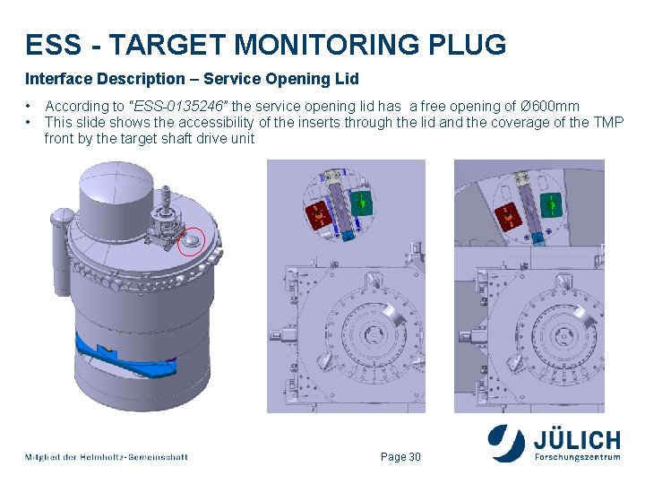
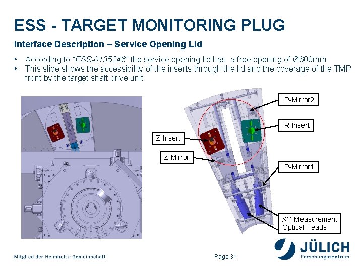
ESS - TARGET MONITORING PLUG Interface Description – Service Opening Lid • • According to “ESS-0135246” the service opening lid has a free opening of Ø 600 mm This slide shows the accessibility of the inserts through the lid and the coverage of the TMP front by the target shaft drive unit Page 30
ESS - TARGET MONITORING PLUG Interface Description – Service Opening Lid • • According to “ESS-0135246” the service opening lid has a free opening of Ø 600 mm This slide shows the accessibility of the inserts through the lid and the coverage of the TMP front by the target shaft drive unit IR-Mirror 2 IR-Insert Z-Mirror IR-Mirror 1 XY-Measurement Optical Heads Page 31
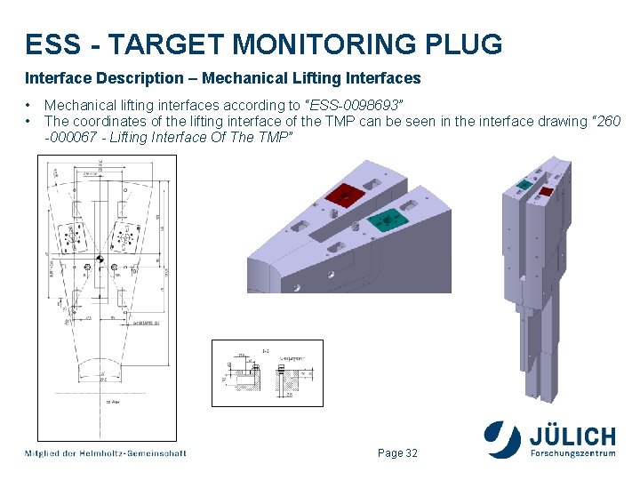
ESS - TARGET MONITORING PLUG Interface Description – Mechanical Lifting Interfaces • • Mechanical lifting interfaces according to “ESS-0098693” The coordinates of the lifting interface of the TMP can be seen in the interface drawing “ 260 -000067 - Lifting Interface Of The TMP” Page 32
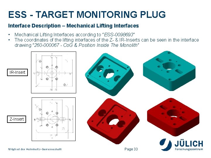
ESS - TARGET MONITORING PLUG Interface Description – Mechanical Lifting Interfaces • • Mechanical Lifting Interfaces according to “ESS-0098693” The coordinates of the lifting interfaces of the Z- & IR-Inserts can be seen in the interface drawing “ 260 -000067 - Co. G & Position Inside The Monolith” IR-Insert Z-Insert Page 33
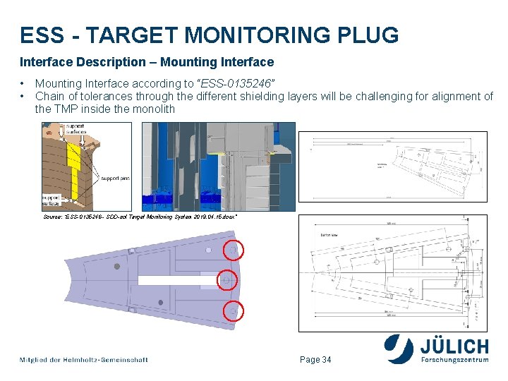
ESS - TARGET MONITORING PLUG Interface Description – Mounting Interface • • Mounting Interface according to “ESS-0135246” Chain of tolerances through the different shielding layers will be challenging for alignment of the TMP inside the monolith Source: “ESS-0135246 - SDD-sol Target Monitoring System 2019. 04. 15. docx” Page 34
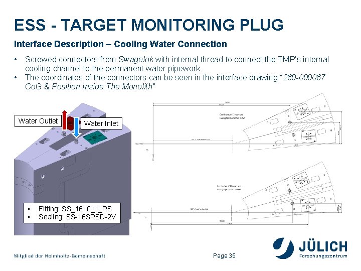
ESS - TARGET MONITORING PLUG Interface Description – Cooling Water Connection • • Screwed connectors from Swagelok with internal thread to connect the TMP’s internal cooling channel to the permanent water pipework. The coordinates of the connectors can be seen in the interface drawing “ 260 -000067 Co. G & Position Inside The Monolith” Water Outlet • • Water Inlet Fitting: SS_1610_1_RS Sealing: SS-16 SRSD-2 V Page 35
OUTLINE ESS – Target Monitoring Plug – System Design Solution 1. Target Monitoring Plug System Overview & Description 2. Overview of main body assembly 3. Overview functional group 100 (XY-measurement) 4. Overview functional group 200 (Z-measurement Insert) 5. Overview functional group 300 (IR-measurement Insert) 6. Interface Description 7. Documentation example Page 36
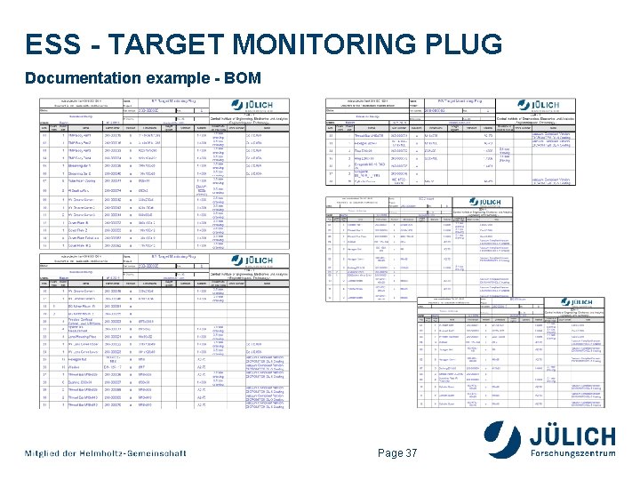
ESS - TARGET MONITORING PLUG Documentation example - BOM Page 37
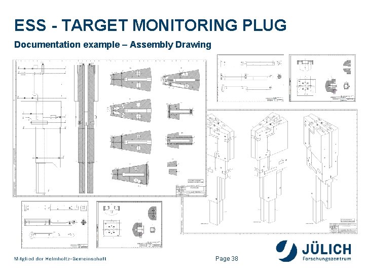
ESS - TARGET MONITORING PLUG Documentation example – Assembly Drawing Page 38
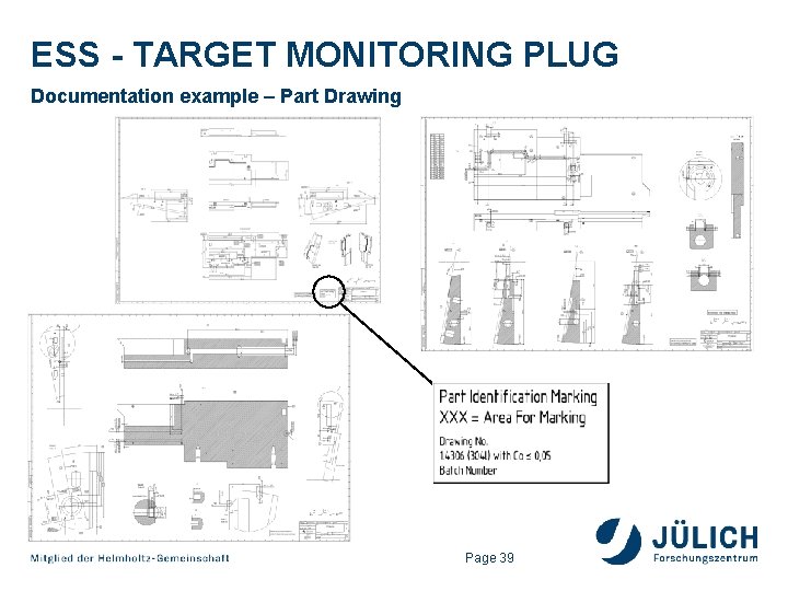
ESS - TARGET MONITORING PLUG Documentation example – Part Drawing Page 39
ESS - TARGET MONITORING PLUG Thank you for your attention! Page 40