System Curve Example Design Condition 20 ft w


- Slides: 23
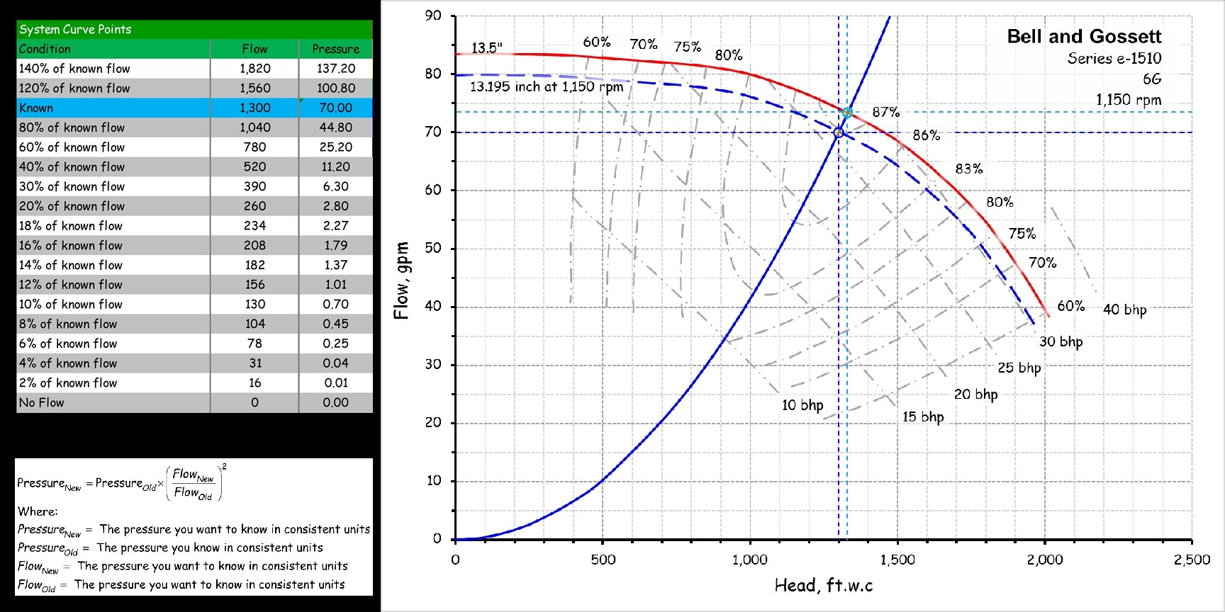
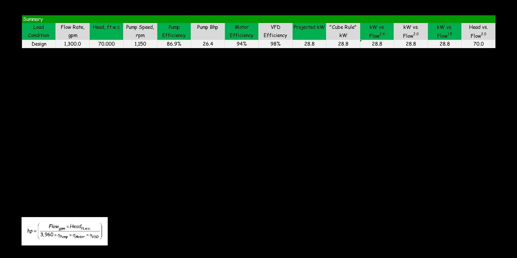
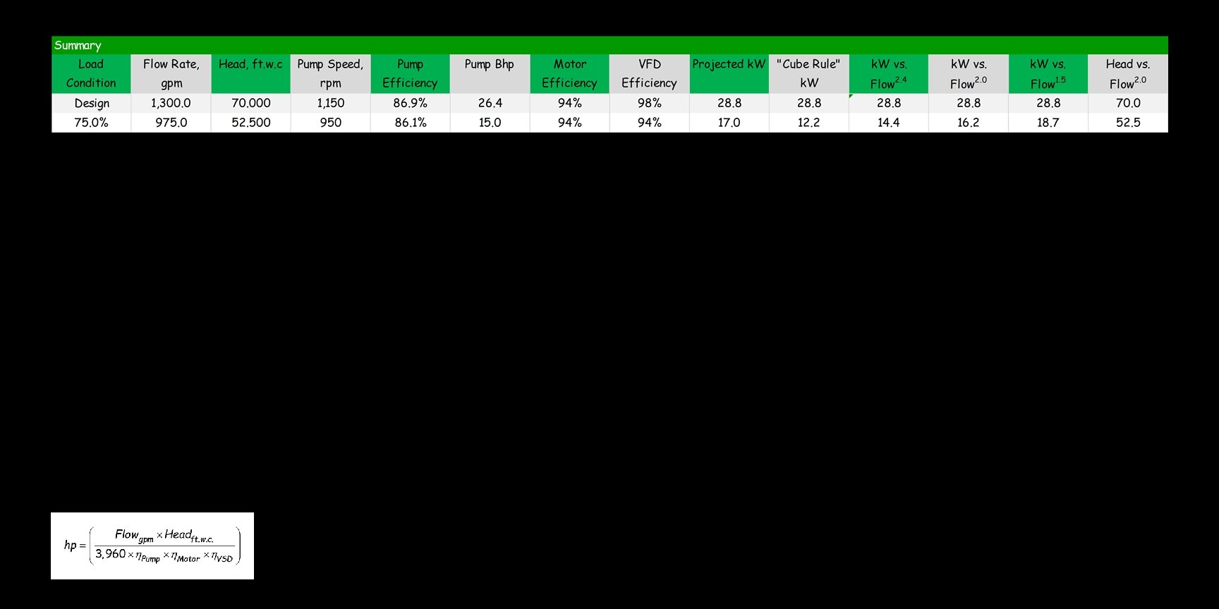
System Curve Example Design Condition 20 ft. w. c. required each way to deliver design flow to and from the headers at the loads Distribution Pump Bell and Gossett 1510 1, 300 gpm at 70 ft. w. c. 1, 150 rpm, η=86. 9% 30 hp 26. 4 bhp Chiller-1 1, 300 gpm Bypass line sized for virtually no pressure drop under all operating conditions Evaporator Pump 1, 300 gpm Use the Principle of Conservation of Mass and Energy to Establish a Flow Profile = 30 ft. w. c. required to deliver the design flow rate through the branch piping, coil, control valve and fittings AHU-1 325 gpm Header sized for virtually no pressure drop under all operating conditions (Typical on the supply and return sides) AHU-2 325 gpm AHU-3 325 gpm AHU-4 325 gpm
System Curve Example Design Condition 20 ft. w. c. required each way to deliver design flow to and from the headers at the loads Distribution Pump Bell and Gossett 1510 1, 300 gpm at 70 ft. w. c. 1, 150 rpm, η=86. 9% 30 hp 26. 4 bhp Chiller-1 1, 300 gpm Bypass line sized for virtually no pressure drop under all operating conditions Evaporator Pump 1, 300 gpm Use the Principle of Conservation of Mass and Energy to Establish a Flow Profile 1. Use a pump test to establish the flow for the constant volume chiller loop 2. Use a data logger to log the chiller temperature drop 3. Calculate the tons produced by the chiller based on the logged temperature drop and the flow you derived from the pump test 30 ft. w. c. required to deliver the design flow rate through the branch piping, coil, control valve and fittings AHU-1 325 gpm Header sized for virtually no pressure drop under all operating conditions (Typical on the supply and return sides) AHU-2 325 gpm AHU-3 325 gpm AHU-4 325 gpm
System Curve Example Design Condition 20 ft. w. c. required each way to deliver design flow to and from the headers at the loads Distribution Pump Bell and Gossett 1510 1, 300 gpm at 70 ft. w. c. 1, 150 rpm, η=86. 9% 30 hp 26. 4 bhp Chiller-1 1, 300 gpm Bypass line sized for virtually no pressure drop under all operating conditions Evaporator Pump 1, 300 gpm Use the Principle of Conservation of Mass and Energy to Establish a Flow Profile 4. Log temperature rise across the distribution loop 5. Take the load developed from the chiller data and calculate the flow in the distribution loop by solving the water side load equation for flow 30 ft. w. c. required to deliver the design flow rate through the branch piping, coil, control valve and fittings AHU-1 325 gpm Header sized for virtually no pressure drop under all operating conditions (Typical on the supply and return sides) AHU-2 325 gpm AHU-3 325 gpm AHU-4 325 gpm
System Curve Example Design Condition 20 ft. w. c. required each way to deliver design flow to and from the headers at the loads Distribution Pump Bell and Gossett 1510 1, 300 gpm at 70 ft. w. c. 1, 150 rpm, η=86. 9% 30 hp 26. 4 bhp 30 ft. w. c. required to deliver the design flow rate through the branch piping, coil, control valve and fittings Chiller-1 1, 300 gpm AHU-1 325 gpm Bypass line sized for virtually no pressure drop under all operating conditions Evaporator Pump 1, 300 gpm Header sized for virtually no pressure drop under all operating conditions (Typical on the supply and return sides) AHU-2 325 gpm AHU-3 325 gpm AHU-4 325 gpm
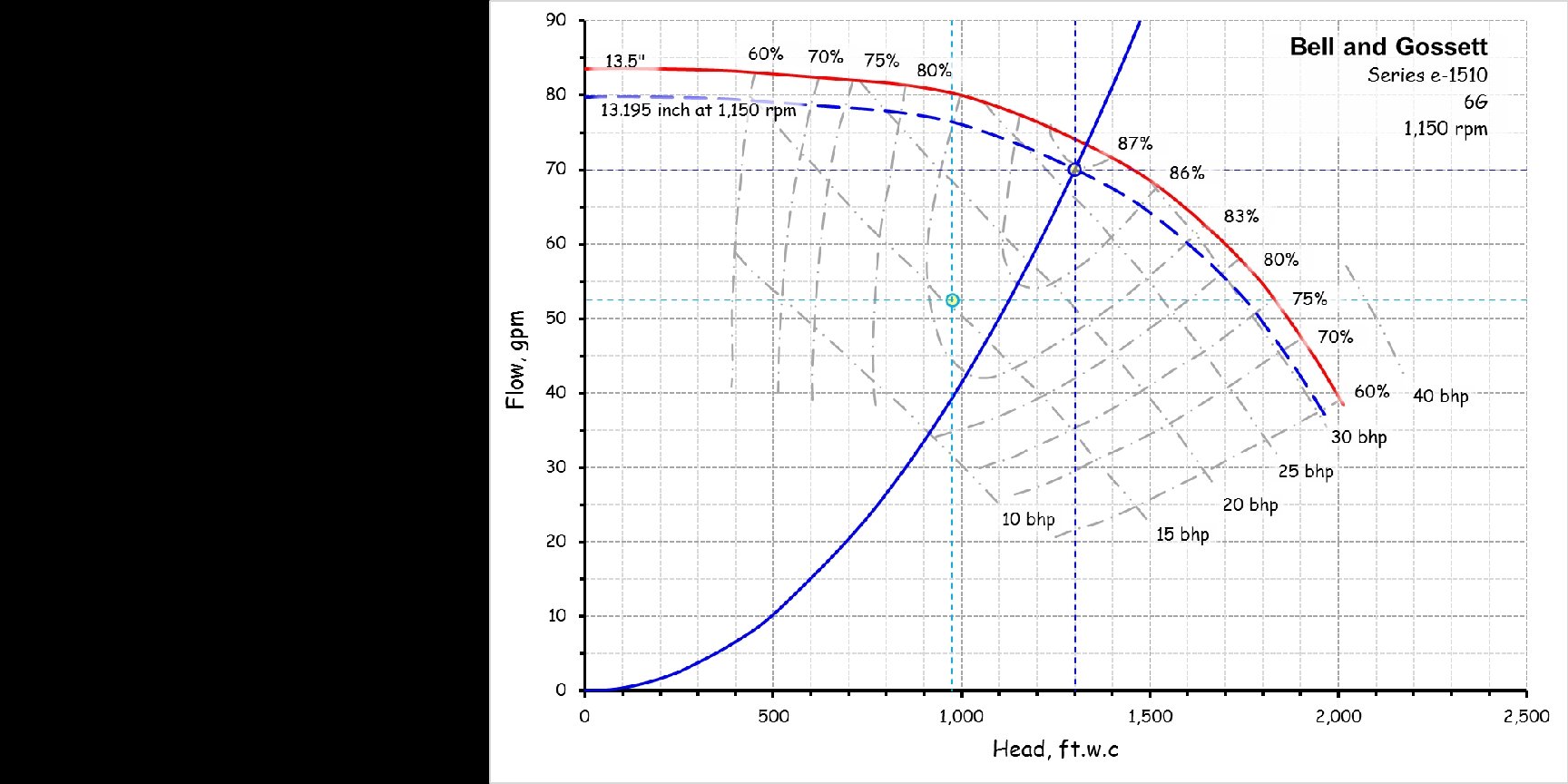
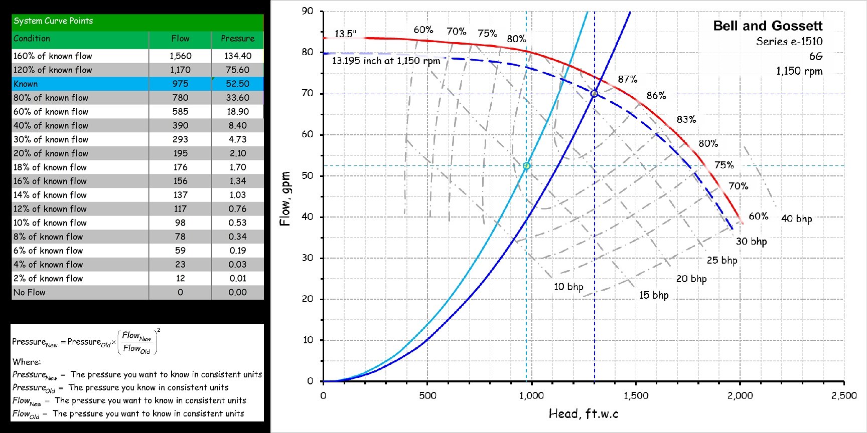
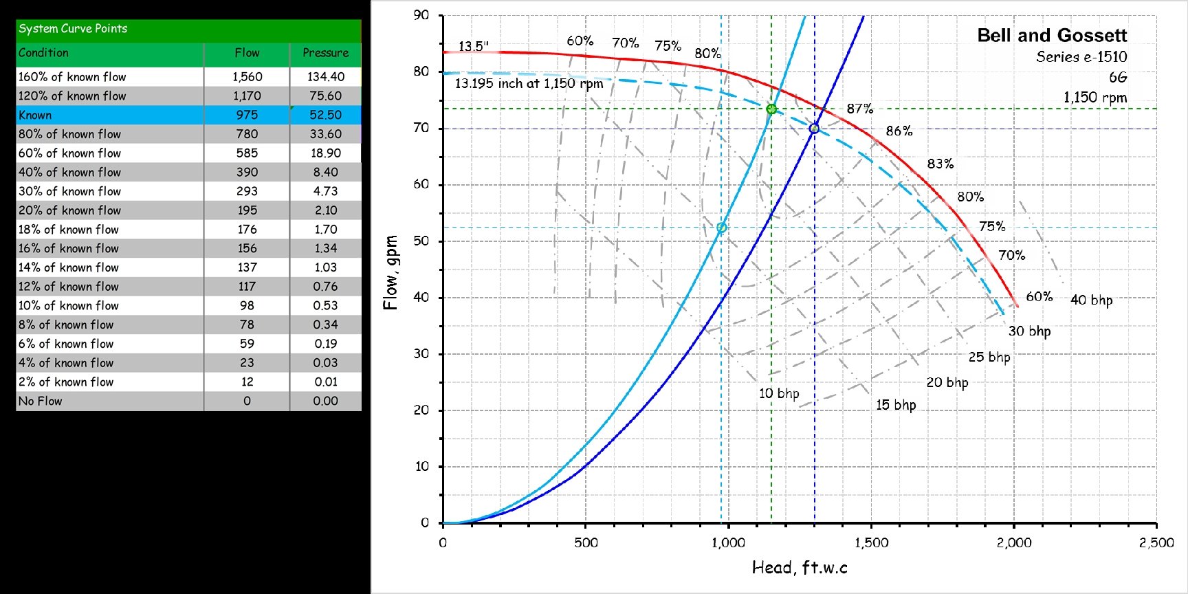
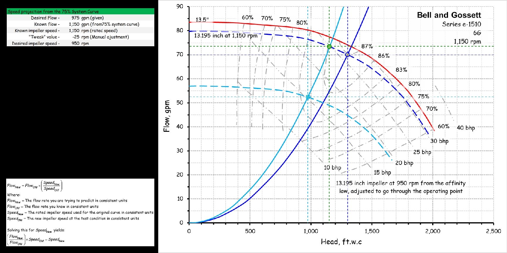
System Curve Example 75% Load Condition 11. 25 ft. w. c. required each way to deliver 75% of the design flow to and from the headers at the loads Distribution Pump Bell and Gossett 1510 975 gpm at 52. 5 ft. w. c. 950 rpm, η=86. 1% 30 hp 15. 0 bhp 30 ft. w. c. required to deliver the design flow rate through the branch piping, coil, control valve and fittings Chiller-1 1, 300 gpm AHU-1 0 gpm Bypass line sized for virtually no pressure drop under all operating conditions Evaporator Pump 1, 300 gpm Header sized for virtually no pressure drop under all operating conditions (Typical on the supply and return sides) AHU-2 325 gpm AHU-3 325 gpm AHU-4 325 gpm
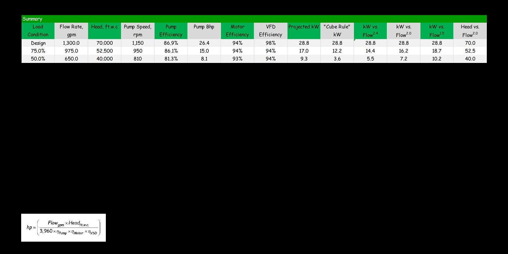
System Curve Example 50 % Load Condition 5 ft. w. c. required each way to deliver 50% of the design flow to and from the headers at the loads Distribution Pump Bell and Gossett 1510 650 gpm at 40 ft. w. c. 810 rpm, η=81. 3% 30 hp 8. 1 bhp 30 ft. w. c. required to deliver the design flow rate through the branch piping, coil, control valve and fittings Chiller-1 1, 300 gpm AHU-1 0 gpm Bypass line sized for virtually no pressure drop under all operating conditions Evaporator Pump 1, 300 gpm Header sized for virtually no pressure drop under all operating conditions (Typical on the supply and return sides) AHU-2 325 gpm AHU-3 325 gpm AHU-4 0 gpm
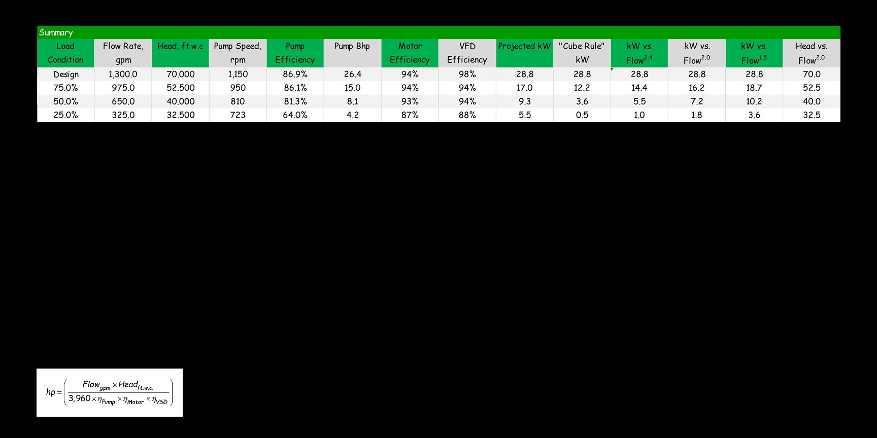
System Curve Example 25 % Load Condition 1. 25 ft. w. c. required each way to deliver 25% of the design flow to and from the headers at the loads Distribution Pump Bell and Gossett 1510 325 gpm at 32. 5 ft. w. c. 723 rpm, η=64. 0% 30 hp 4. 2 bhp 30 ft. w. c. required to deliver the design flow rate through the branch piping, coil, control valve and fittings Chiller-1 1, 300 gpm AHU-1 0 gpm Bypass line sized for virtually no pressure drop under all operating conditions Evaporator Pump 1, 300 gpm Header sized for virtually no pressure drop under all operating conditions (Typical on the supply and return sides) AHU-2 325 gpm AHU-3 325 gpm AHU-4 0 gpm
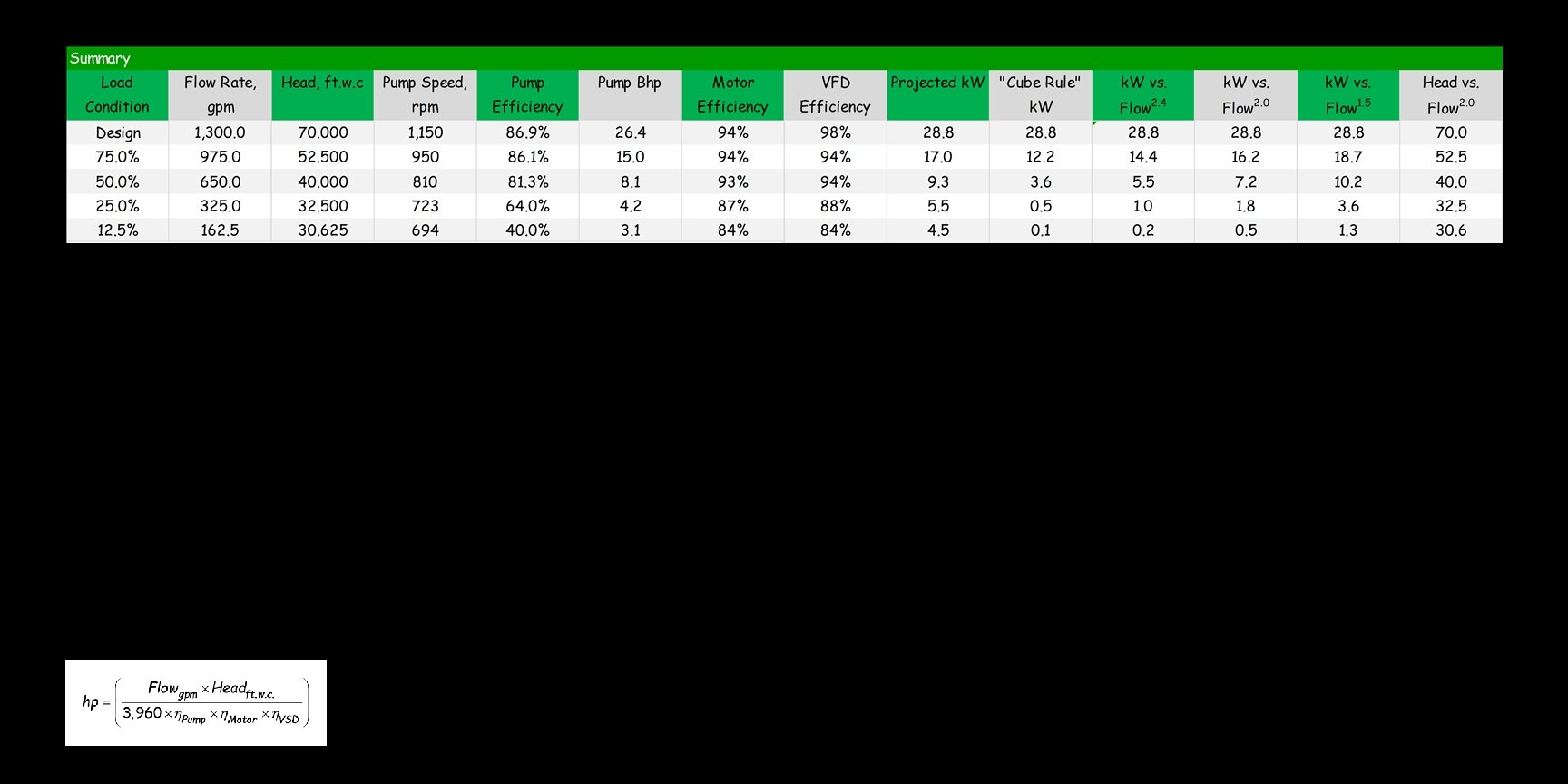
System Curve Example 12. 5 % Load Condition 0. 3125 ft. w. c. required each way to deliver 12. 5% of the design flow to and from the headers at the loads Distribution Pump Bell and Gossett 1510 162. 5 gpm at 30. 625 ft. w. c. 694 rpm, η=64. 0% 30 hp 3. 1 bhp 7. 5 ft. w. c. required to deliver 50% of the design flow rate through the branch piping, coil, control valve and fittings Chiller-1 1, 300 gpm AHU-1 0 gpm Bypass line sized for virtually no pressure drop under all operating conditions Evaporator Pump 1, 300 gpm Header sized for virtually no pressure drop under all operating conditions (Typical on the supply and return sides) AHU-2 162. 5 gpm AHU-3 325 gpm AHU-4 0 gpm