
System behaviors state machine diagrams Capture the admissible

System behaviors: state machine diagrams • Capture the admissible behaviors of system components • Behavior of component instance = sequence of state transitions for the items it controls • SM state = set of situations where a variable characterizing a controlled item has always the same value – e. g. state Meeting. Scheduled: always same value for Date, Location (while other variable With. Whom on Meeting may change value) – Initial, Initial final states = states where item appears, disappears – States may have some duration • SM state transition: transition caused by associated event – if item in source state and event ev occurs then it gets to target state – Events are instantaneous phenomena © 2009 John Wiley and Sons www. wileyeurope. com/college/van lamsweerde
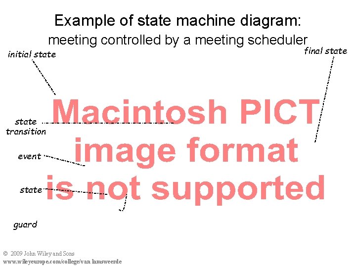
Example of state machine diagram: meeting controlled by a meeting scheduler initial state transition event state guard © 2009 John Wiley and Sons www. wileyeurope. com/college/van lamsweerde final state
State machine diagrams: transitions and guards • Event occurrence is a sufficient condition for transition firing – Event can be external stimulus (e. g. meeting. Request) or application of internal operation (e. g. determine. Schedule) • Guard = necessary condition for transition firing – Item gets to target state. . . • if item is in source state and event ev occurs and only if guard condition is true – Guarded transition with no event label: fires as soon as guard gets true (= trigger condition) • Non-deterministic behavior: multiple outgoing transitions with same event and no or overlapping guards – often to be avoided for safety, security reasons © 2009 John Wiley and Sons www. wileyeurope. com/college/van lamsweerde
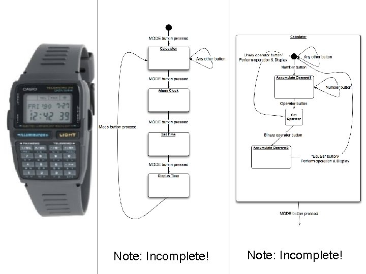
Note: Incomplete!
System operations: use case diagrams • Capture operations to be performed by a system component & interactions with other components – yet simpler, outline view. . . but vague – to be made precise by annotations, interaction scenarios, . . . – introduced in UML to replace DFDs • Structuring mechanisms. . . – <<include>>: to specify “suboperation” – <<extend>> + precondition: to specify “variant” operation in exception case © 2009 John Wiley and Sons www. wileyeurope. com/college/van lamsweerde
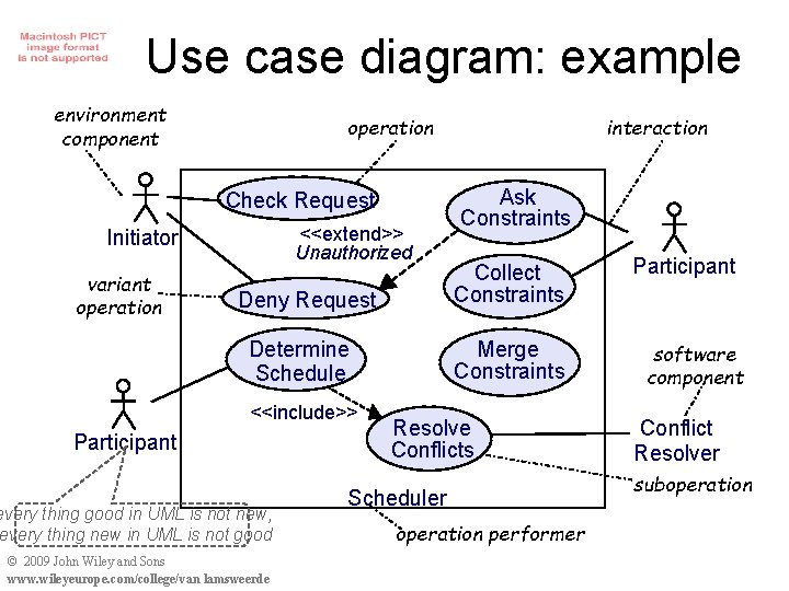
Use case diagram: example environment component operation Check Request <<extend>> Unauthorized Initiator variant operation Deny Request Participant every thing good in UML is not new, every thing new in UML is not good © 2009 John Wiley and Sons www. wileyeurope. com/college/van lamsweerde Ask Constraints Collect Constraints Merge Constraints Determine Schedule <<include>> interaction Resolve Conflicts Scheduler operation performer Participant software component Conflict Resolver suboperation
But Wait! Consider Use Cases First • Use case: a set of scenarios tied together by a common goal • Example: – Process Sale: A customer arrives at a checkout with items to purchase. The cashier uses the POS system to record each purchased item. The system presents a running total and line-item details. The customer enters payment information, which the system validates and records. The system updates inventory. The customer receives a receipt from the system and leaves with the items.
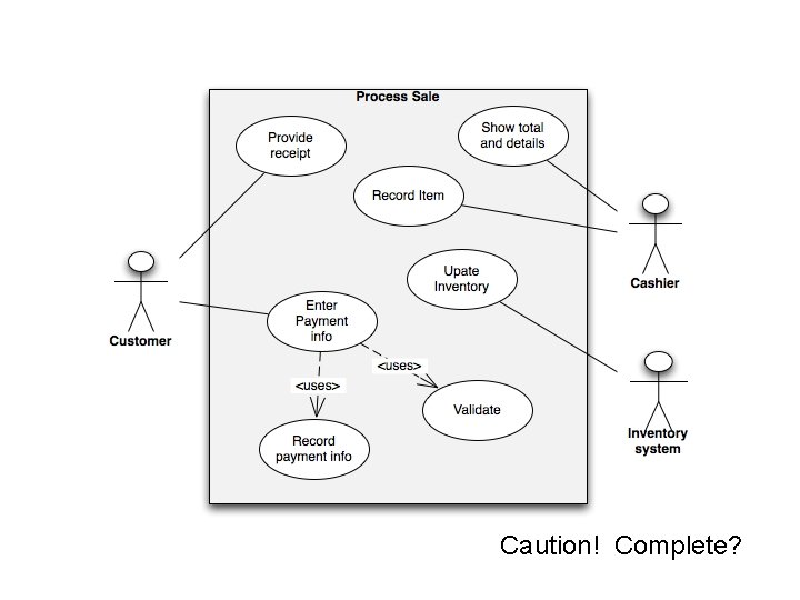
Caution! Complete?
Interaction scenarios: event trace diagrams • Capture positive scenarios by sequences of interactions among instances of system components (cf. Chap. 2) – variants: MSC (ITU), sequence diagrams (UML, cf. Chap. 13) • Parallel composition of timelines – one per component instance • Pairwise directed interactions down timelines – information transmission through event attributes • Interaction event synchronously controlled by source instance & monitored by target instance – total order on events along timeline (event precedence) – partial order on all diagram events © 2009 John Wiley and Sons www. wileyeurope. com/college/van lamsweerde
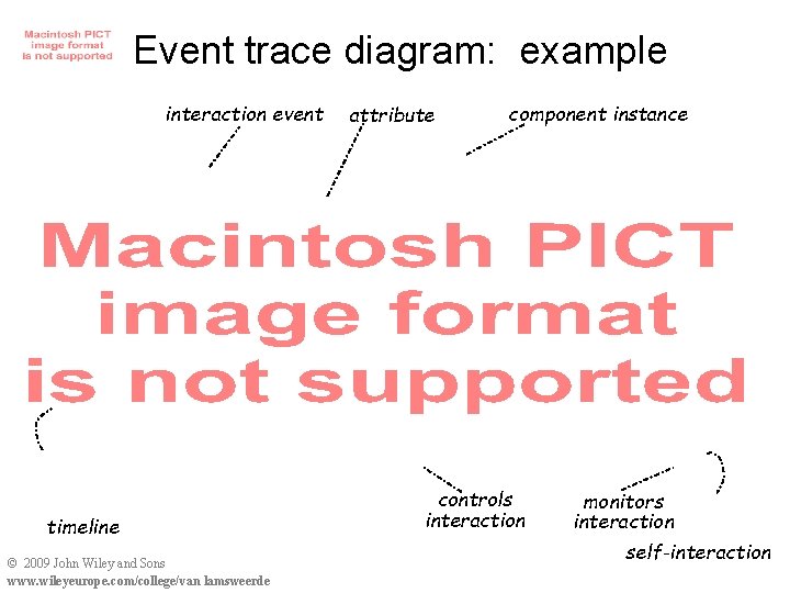
Event trace diagram: example interaction event timeline © 2009 John Wiley and Sons www. wileyeurope. com/college/van lamsweerde attribute component instance controls interaction monitors interaction self-interaction
Scenarios and state machines • SM trace = sequence of successive SM states up to some point – e. g. < Gathering. Meeting. Data, Request. Denied > – always finite, but SM diagram may have infinitely many traces • A SM diagram generalizes ET diagram scenarios: – from specific instances to any component instance – trace coverage: SM traces include ET traces, and (many) more e. g. scenario/SM trace from previous slides: < Validating. Meeting. Data; Constraints. Requested; Planning; Meeting. Scheduled; Meeting. Notified > © 2009 John Wiley and Sons www. wileyeurope. com/college/van lamsweerde
Concurrent behaviors and statecharts • Components often control multiple items in parallel • Problems with flat SM diagram. . . – N item variables each with M values => MN states ! – same SM state mixing up different variables • Statechart = parallel composition of SM diagrams [Harel, 1987] – one per variable evolving in parallel – statechart state = aggregation of concurrent substates – from MN explicit SM states to M ´ N statechart states ! • Statechart trace = sequence of successive aggregated SM states up to some point • Interleaving semantics: for 2 transitions firing in same state, one is taken after the other (non-deterministic choice) © 2009 John Wiley and Sons www. wileyeurope. com/college/van lamsweerde
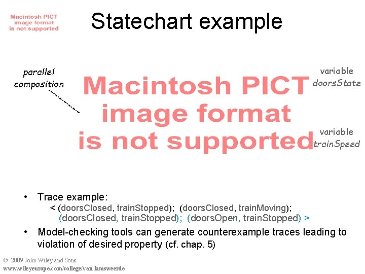
Statechart example parallel composition variable doors. State variable train. Speed • Trace example: < (doors. Closed, train. Stopped); (doors. Closed, train. Moving); (doors. Closed, train. Stopped); (doors. Open, train. Stopped) > • Model-checking tools can generate counterexample traces leading to violation of desired property (cf. chap. 5) © 2009 John Wiley and Sons www. wileyeurope. com/college/van lamsweerde
- Slides: 13