Synchrophasor Implementations Prepared by Tony Weekes Husam Al

Synchrophasor Implementations Prepared by Tony Weekes Husam Al Hadidi Brian Archer

Topics of Discussion �Description of Manitoba WAMS �Introduction to Birchtree SVC Project �Commissioning Results �Lessons Learned and Future Road Map

Organization Ameren PDC Contracted Connected PMU Confirmed Sites Connected Devices 1 1 21 6 N/A 1 N/A 5 Duke Energy 1 1 16 4 Great Rivers Energy 1 1 8 2 Hoosier Energy 1 1 7 9 Indianapolis P&L 1 1 6 7 International Trans Co. 1 1 12 5 Manitoba Hydro 2 1 22 6 Mid. American Energy 1 0 12 0 Minnesota Power 1 1 4 1 Montana Dakota Utilities 0 0 5 0 Northern Indiana Public Service 3 1 8 2 Ottertail Power 2 1 6 3 Vectren 1 0 3 0 WAPA 0 0 4 0 XCEL Energy 0 0 11 0 TOTAL 16 11 145 50 American Trans Co.

Need for wide Area Measurements �Typical PSS tuning monitors local signals �Problems can arise with fighting between controllers �Advantage of monitoring a wide area can be addressed with synchrophasors

WAMS �Phasorpoint tool used primarily to see the modes on the system

Phasor Point Mode Charting Mode Power Path

Sites Chosen �known inter-area modes in our Northern ac. �sensitivities of modes to various power flow conditions �Upcoming projects in Northern ac �Future sites will increase from 6 to 30 PMU locations �Using existing TFR devices

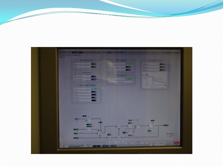
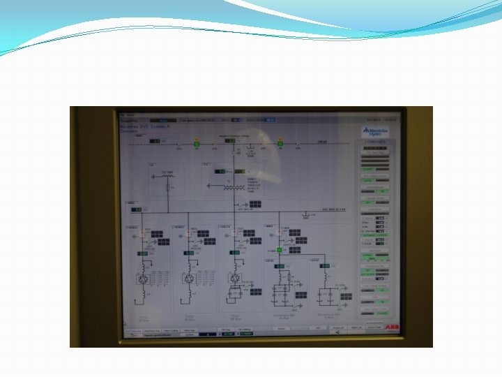
Birchtree SVC Controller
")
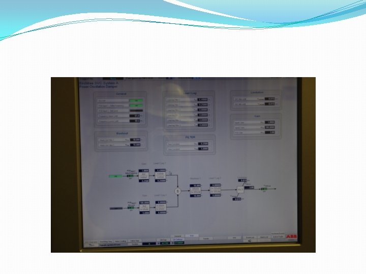
Power Oscillation Damper (POD)

Commissioning Objectives �Transfer function verification of the SVC voltage and POD controllers �Tuning the POD to provide good damping performance for the modes within the frequency range of interest 0. 5 to 0. 9 Hz �Minimize the interaction between the Ponton SVC and Birchtree SVC �Optimize the Birchtree SVC POD and Ponton SVC SDC settings for most northern ac system generation patterns and operating conditions

Risks and Mitigations � Output is correctly controlled from input, as expected �Check the degree of movement in the rest of the system in response to a step change �Confirm consistency with time-domain measurements �Decide criteria for “unacceptable” oscillations. �Switch controllers off one-by-one or plant-by-plant, separated by a period of time.
 of SVC POD design Phase Magnitude The")
System Frequency Response �Model verification (frequency response) of SVC POD design Phase Magnitude The frequency response characteristic (magnitude and phase) of the transfer function between Birchtree SVC input and voltage angle (frequency

�Faciltity and Phasor Point screen

Mode Trending Root locus of mode �Trending and verification of damping controller performance Observability of the mode over time

Commissioning Results

Unexpected Results Captured �Mode increases with lower power �Initial response of POD with other settings �Clock error

Cont…. . System Baselining

Cont…. . System Baselining April 25, 2011 – 11: 14: 00 to 11: 19: 00 – Approx. 2 hours before event Clock Errors

POD First Settings

POD Second Settings

Open/Close line test

Open/Close Line Test

Open/Close Line Test

SLG Fault
 �Importance of doing")
Lessons Learned �Channel Selection (problem with power calculation if switching occurs) �Importance of doing a frequency response intially to confirm models �Real time feedback to see if and how multiple power system controllers may fight with each other. �Clock errors can be significant and need mitigation measures both in real time and regular maintenance �Integration of analog signals in the future to PMU data (also significance of proper channel selection and sites) �Unusual Modes were identified as consistently observed on the system but low in magnitude
 �Investigations to increase transfer limits through")
Future Road Map �Model verification (complement NERC testing) �Investigations to increase transfer limits through compound event analysis �Investigation of islanding and coherency of generators �Integration with real time tools that use power models (benchmarking) �EMS state estimator improvement especially after the full complement of PMUs are on the system

Questions ? ?

Cont…. . System Baselining May 3, 2011

Cont…. . System Baselining May 25, 2011
")
Bode Plot (Lead /lag Block)

Simulation Results Time Domain

Cont…. . System Baselining April 25, 2011 – 13: 00 to 13: 18: 00 – During the time of the Event

Cont…. . System Baselining May 3, 2011 – 09: 00 to 09: 05: 00 – About a week after the event

Cont…. Simulation Results �Frequency Domain

Commissioning tests �Frequency sweep and discrete frequency injection �MW transfer change � 5% Step response of genertor exciter �Open/ close line switching �SLG Fault

Kettle Exciter Step Change

Small-signal stability problems �Local plant mode oscillations: Rotor angle oscillations of single generator or single plant against the rest of the system (0. 7 to 2. 0 Hz). �Intermachine/Interplant mode of oscillations: Rotor angle oscillations between a few generator close to each other (0. 7 to 2. 0 Hz). �Interarea mode oscillations: Oscillations of groups of generators in one area swinging against a groups of generators in another area (0. 1 to 0. 7 Hz). �Control mode oscillations: Associated with control of equipment such as generator excitation systems (2. 0 to 5. 0 Hz).

Open/Close Line Test

Open/Close Line test

Commissioning Plan �Time domain and frequency domain simulation studies �System Baselining (using the PMU and Psymetrix tools) �Test schedule & planning �Commissioning test process �Results analysis
- Slides: 44