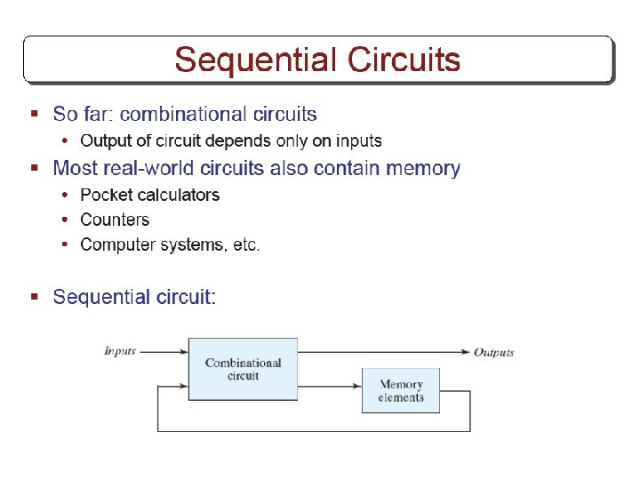
Synchronous Sequential Logic Chapter 5 Other Flip Flops


 flip flop § It is a complementing ff. § J and K")
 refers to the presents state. Q(t+1) refers to the next state.")
=D § JK flip flop Q(t+1)=JQ’+K’Q § T")


 § The next state values can also be")

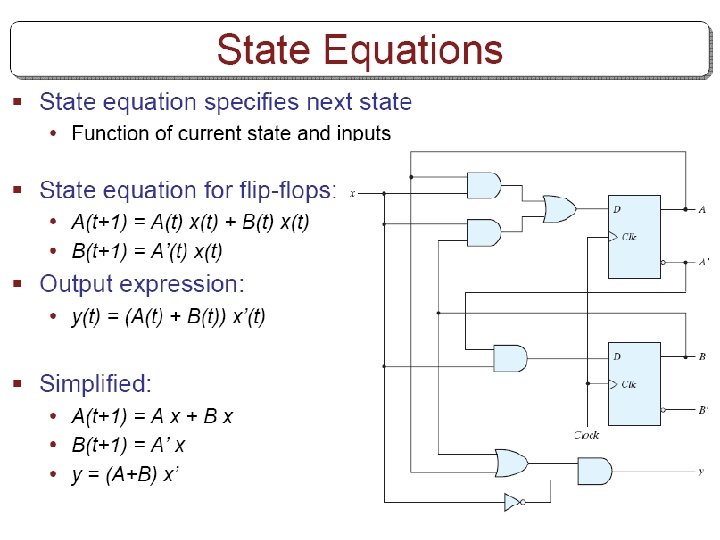
=A’B+AB’+Ax B(t+1)=B’x’+ABx+A’Bx’")


=AB’+Ax’+A’Bx B(t+1)=x’B+x. B’=x(XOR)B y=AB Obtain state table")


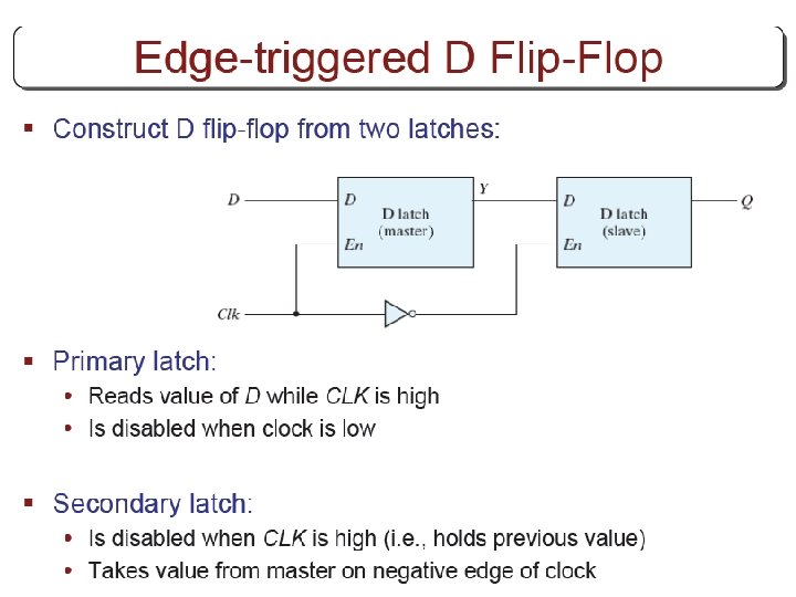
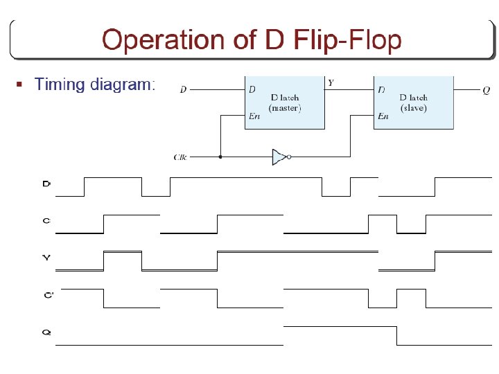
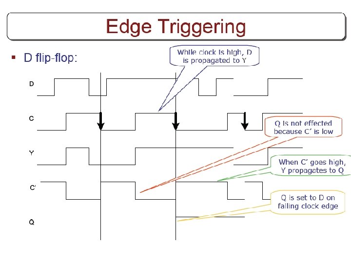
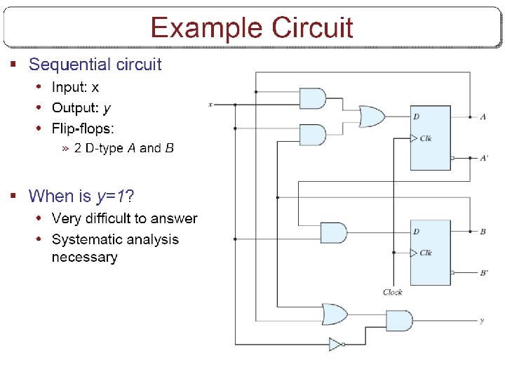
 A sequential circuit with two D flip-flops")
 Derive the state table and the state")
 Design a sequential circuit with two D")
 Design a sequential circuit with two JK")
 A sequential circuit has three flip-flops A,")
- Slides: 87
Synchronous Sequential Logic Chapter 5
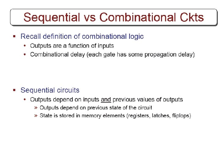
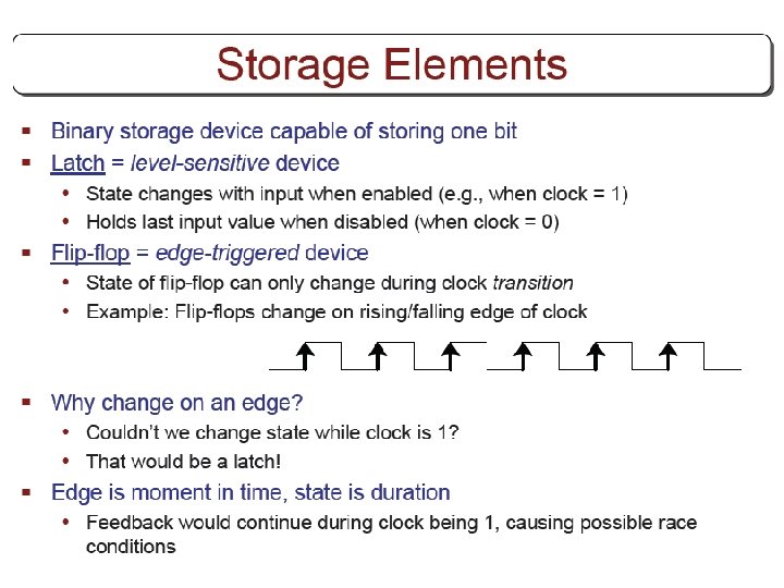
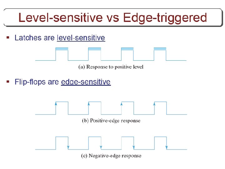
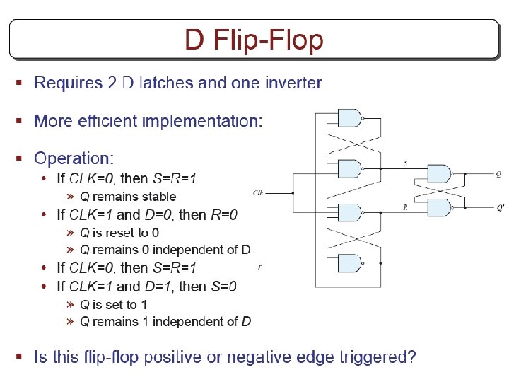
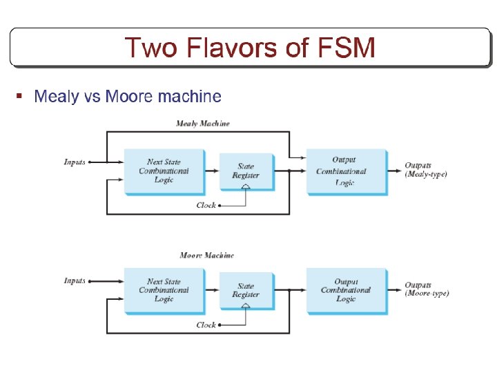
Other Flip Flops § D flip flops requires smallest number of gates. § Thus, they are commonly used § Other flip flops are • JK flip flops • T flip flops
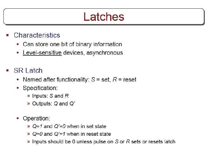
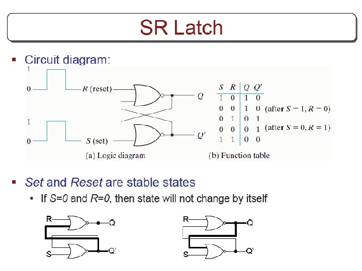
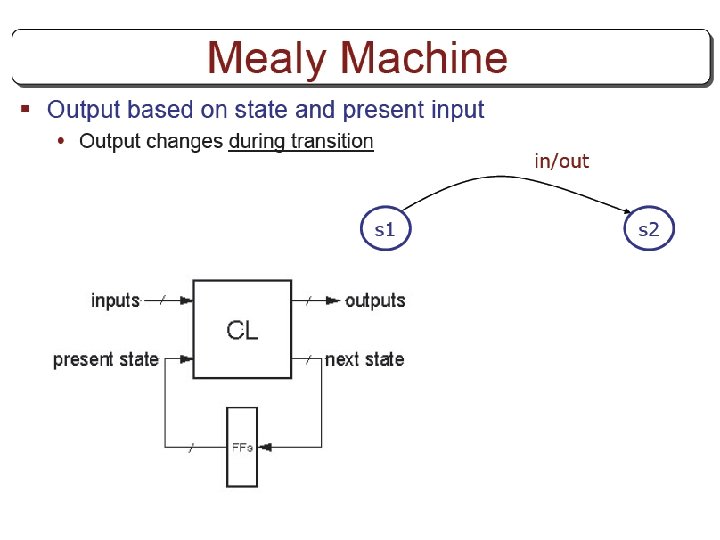
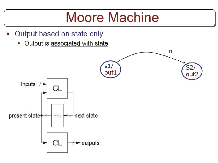
Three operations of flip flops § Three operations that can be performed with flip flops are • Set it to 1 • Reset it to 0 • Complement its output § D flip flop can only set and reset § JK has two inputs and can perform all three operations
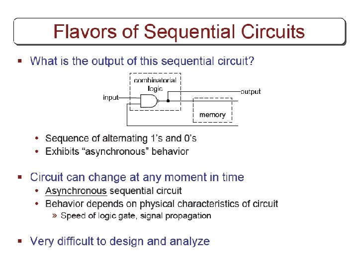
JK flip flop § J input sets to 1 § K input resets to 0 § When both inputs are enabled, output is complemented.
JK flip flop § The function of the D input: D=JQ’+K’Q • • When J=1 AND K=0, D=Q’+Q=1 When J=0 AND K=1, D=0 When J=1 AND K=1, D=Q’ (complemented) When J=0 AND K=0, D=Q (unchanged)
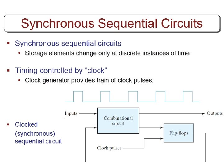
T (toggle) flip flop § It is a complementing ff. § J and K are tied together (Fig a) • When T=0 (J=K=0), no change • When T=1 (J=K=1), complement § Can be constructed from D ff (Fig b) • When T=0, D=Q (no change) • When T=1, D=Q’ (complement)
Characteristic Tables Q(t) refers to the presents state. Q(t+1) refers to the next state.
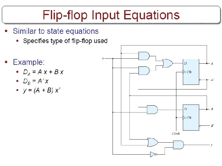
Characteristic Equations § D flip flop Q(t+1)=D § JK flip flop Q(t+1)=JQ’+K’Q § T flip flop
Analysis with JK flip-flops § For D flip-flops, state equation is the same as the input equation. § For JK and T flip-flops, we refer to characteristic equations. § The next state values for JK and T ffs can be derived as follows: • 1. Determine the ff input equation in terms of present state and input variables. • 2. List the binary values of each input equation. • 3. Use ff characteristic table to determine the nextstate values in the state table.
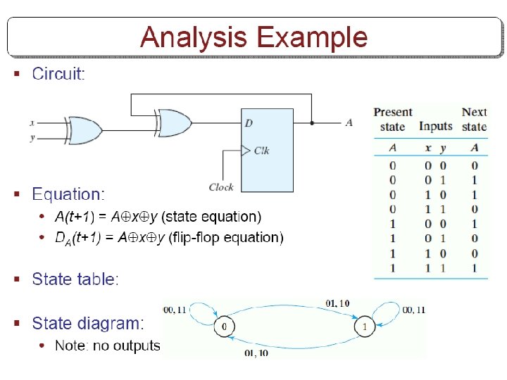
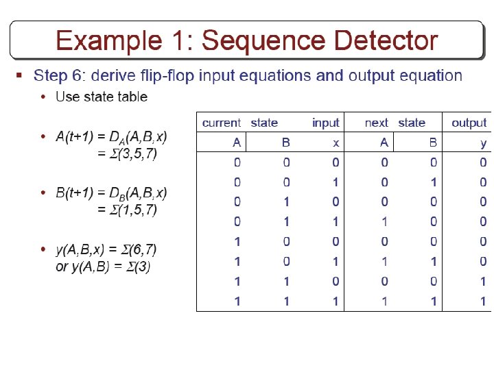
Example § Circuit has no outputs. • No need for output column § FF input eq. s JA=B , KA=Bx’ JB=x’ , KB=A’x+Ax’
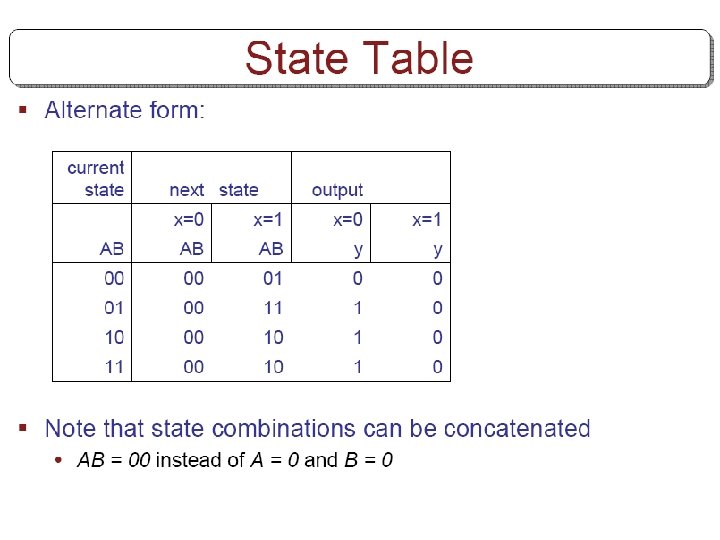
State Table of Example
2 nd method (using state equations) § The next state values can also be obtained by evaluating the state equations: • 1. Determine the ff input equations. • 2. Substitute the input equations into ff characteristic equations to obtain the state equations. • 3. Use the corresponding state equations to determine the next state values.
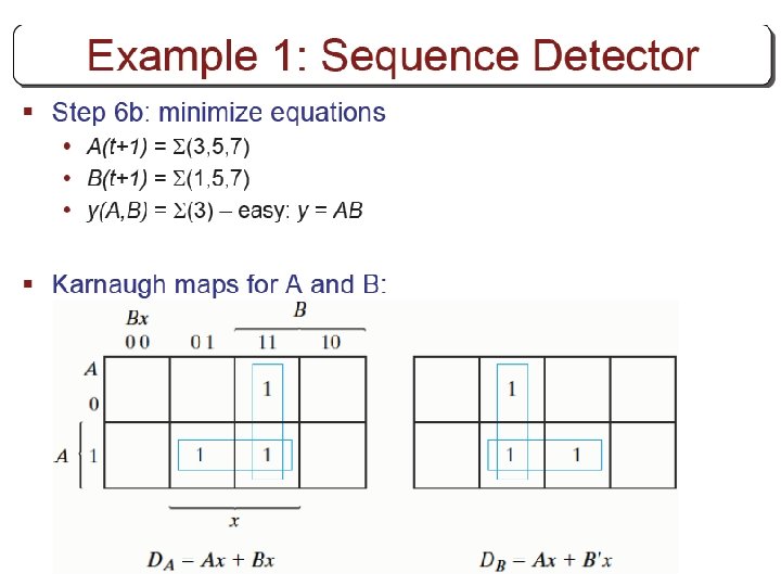
Using state equations § 1. Determine ff equations JA=B , KA=Bx’ JB=x’ , KB=A’x+Ax’ § 2. Substitude them into ff characteristic eq. s: • A(t+1)=JA’+K’A=BA’+(Bx’)’A=A’B+AB’+Ax • B(t+1)=JB’+K’B= § 3. Using state equations, obtain next state values.
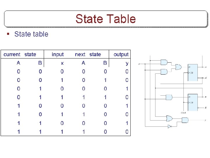
From state equations to state table A(t+1)=A’B+AB’+Ax B(t+1)=B’x’+ABx+A’Bx’
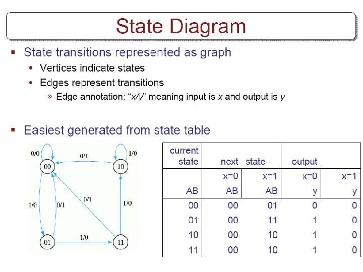
State diagram § Obtain state diagram
Analysis with T Flip-Flops § Same procedure as explained for JK ffs • Either use • Characteristic table or • Characteristic equations § Characteristic equations for T ffs
Example § Input eq. s, output eq. TA=Bx TB=x y=AB § Substitute them into characteristic eq. s A(t+1)=(Bx)’A+(Bx)A’ =AB’+Ax’+A’Bx B(t+1)=x’B+x. B’=x(XOR)B
Example A(t+1)=AB’+Ax’+A’Bx B(t+1)=x’B+x. B’=x(XOR)B y=AB Obtain state table
State diagram § Obtain state diagram
Excitation Tables § When we use D ff, state equations is found directly from the next state. • We cannot do this for JK and T ffs • We need function table for these ffs § The table that lists the required ff inputs for the transitions from present state to next state is called excitation table. • Values for the present state and next state is given. • What values should be applied to flip-flop inputs?
Excitation Table for JK and T
Synthesis Using JK Flip-Flops § Apply the same procedure as we did for D flipflops • Except that the input equations should be evaluated by using excitation tables.
Example
Draw the circuit
Synthesis Using T Flip-Flops § Design a 3 -bit binary counter • At each clock transition, the value of the state will be increased by one • 000, 001, 010, 011…. 111, 000, …. . • Draw the state diagram
Binary counter § Create the state table
FF Input Functions
Counter circuit
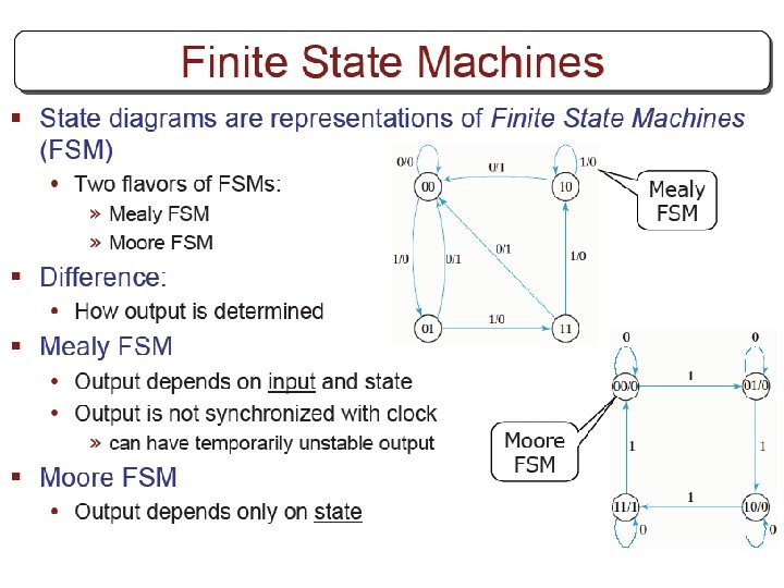
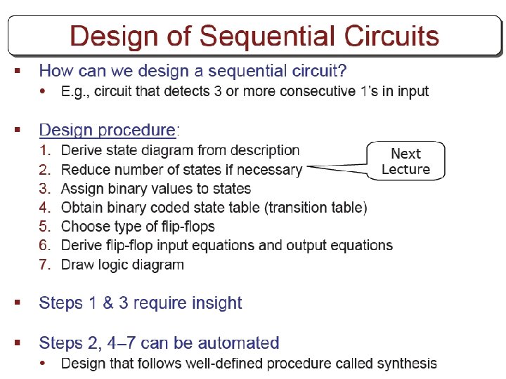
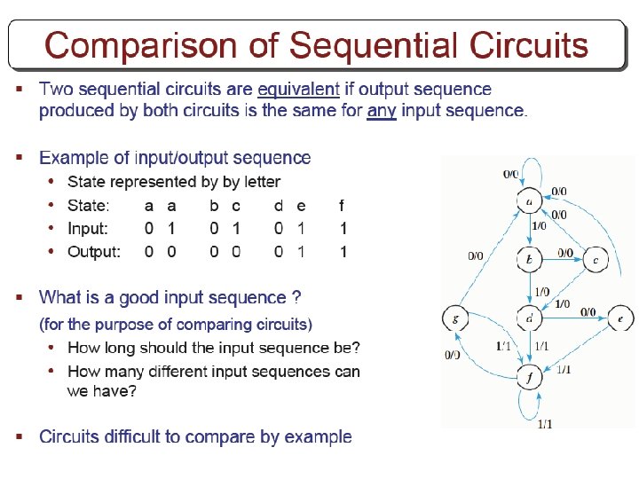
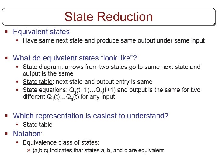
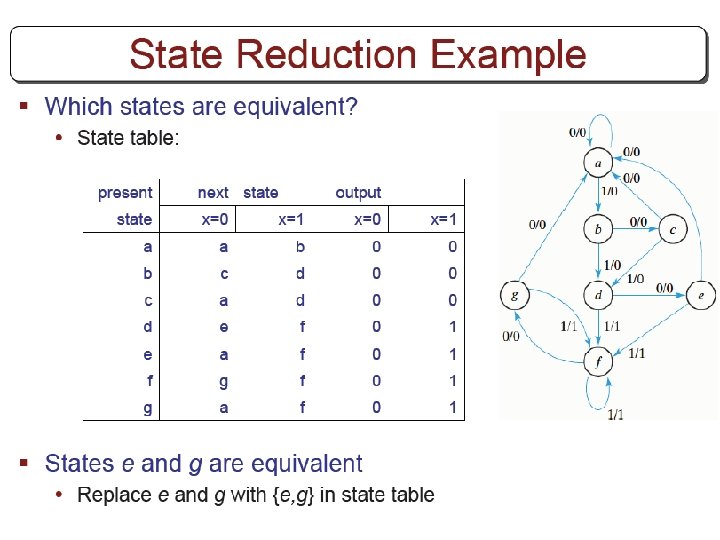
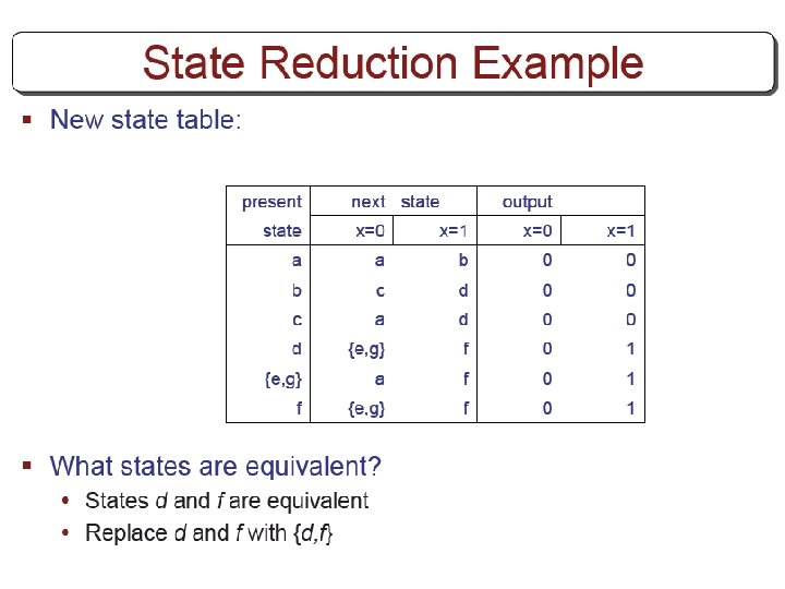
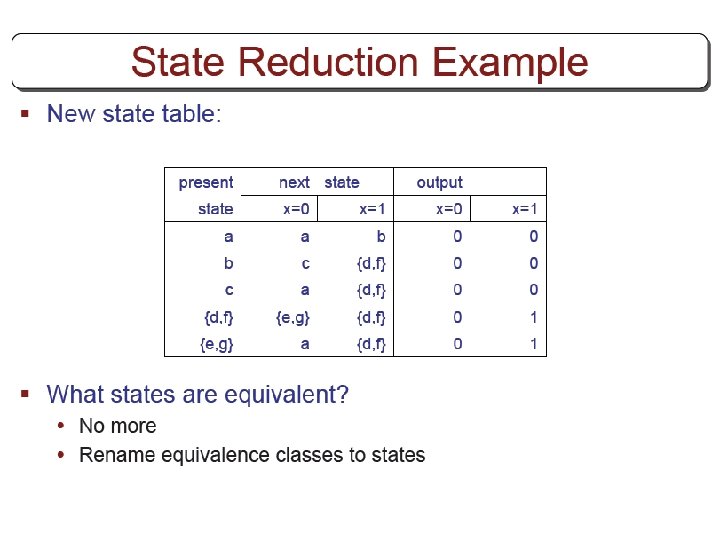
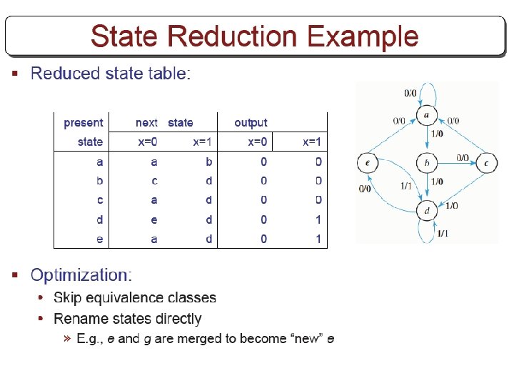
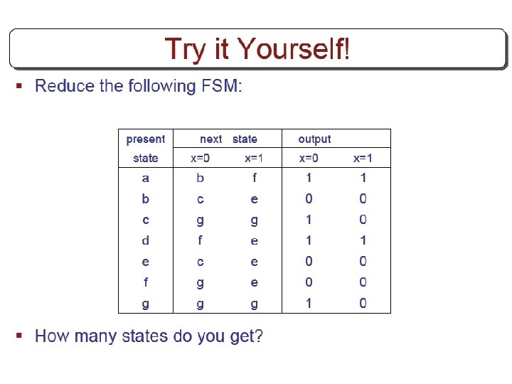
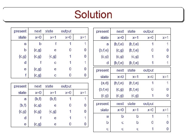
FSM State Reduction
Questions - 1 § (Q. 5. 5) A sequential circuit with two D flip-flops A and B, two inputs x and y, and one output z is specified by the following next state and output equations A(t+1)=x’y+x. B B(t+1)=x’A+x. B Z=A a) Draw the logic diagram of the circuit. b) List the state table for the sequential circuit. c) Draw the corresponding state diagram.
Questions - 2 § (Q. 5. 6) Derive the state table and the state diagram of the sequential circuit shown below. Explain the function that the circuit performs.
Questions - 3 § (Q. 5. 12) Design a sequential circuit with two D flip-flops A and B and one input x_in. a) When x_in=0, the state of the circuit remains the same. When x_in=1, the circuit goes through the state transitions from 00 to 01, to 10, back to 00, and repeats. b) When x_in=0, the state of the circuit remains the same. When x_in=1, the circuit goes through the state transitions from 00 to 11, to 01, to 10, back to 00, and repeats.
Questions - 4 § (Q. 5. 14) Design a sequential circuit with two JK flip-flops A and B and two inputs E and F. • If E=0, the circuit remains in the same state regardless of the value of F. • When E=1 and F=1, the circuit goes through the state transitions from 00 to 01, to 10, to 11, back to 00, and repeats. • When E=1 and F=0, the circuit goes through the state transitions from 00 to 11, to 10, to 01, back to 00, and repeats. • (Up and down counter with enable. Count up when F=1, count down when F=0. )
Questions - 5 § (Q. 5. 15) A sequential circuit has three flip-flops A, B, and C; one input x_in; and one output y_out. The state diagram is shown at right. The circuit is to be designed by treating the unused states as don’t-care conditions. Analyze the circuit obtained from the design to determine the effect of the unused states. • Use D flip-lops in the design. • Use JK flip-flops in the design.