Syn Gasifier ALTERNATIVE ENERGY Technology Presentation COAL GASIFICATION


")


")


 65. 1% 34. 9% 31. 3% http: //www. eia.")


- Slides: 43
Syn. Gasifier ALTERNATIVE ENERGY Technology Presentation
COAL GASIFICATION versus COAL COMBUSTION
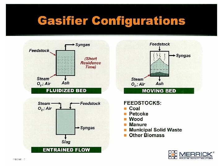
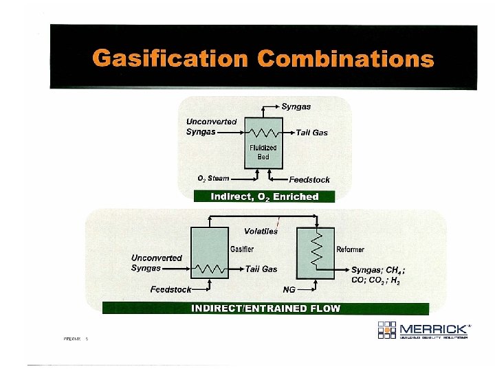
Basic Gasification Technology • Dry Feed Entrained Flow Gasifier using: – Pyrolysis – Thermal conversion or destruction of organics in the absence of oxygen (reducing atmosphere). – Gasification – Thermal conversion of organic materials at elevated temperatures and reducing conditions to produce syngas (Hydrogen and Carbon Monoxide) – Steam Reformation – Vaporized water (steam) added to carbon creates syngas (Hydrogen and Carbon Monoxide)
From: NREL: Biomass Gasification Overview, Richard L. Bain, January 28, 2004
Provisional Patent Effective Date: April 11, 2006 Patent Pending Effective Date:
Exclusive Patent Rights Assigned To Thermal Conversions, LLC
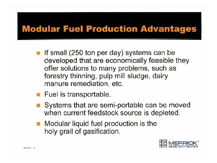
175 dry ton per day Gasification Plant
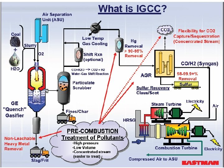
www. eastman. com/company/gasification/overview. htm
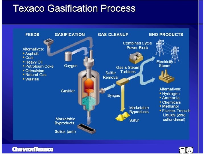
Coal Syngas 12, 500 BTU Variable gas compositions available depending upon operation parameters Heat up to 1800° F Pressure 80 psi • • • Carbon Dioxide Carbon Monoxide Hydrogen Methane Other • Ash Plus Ionized Water Injection Gasification – – – Sulfur Silica Mercury Chlorine Sodium, etc Feed for Chemical/ Refinery Processes and Electrical Generation Removed
Energy Mass Balance (Btu Basis)
Syngas composition operating range for pyrolysis/steam reforming system which includes the range of H 2: CO most desirable for production of synthesis fuels. Data collected on pilot scale pyrolysis/steam reforming system operated on biomass feedstock. (Schuetzle, et al. 2007)
Gasification Chemistry • The following chemical equations describe the process that takes place in the conversion of coal or other carbonaceous fuels into synthesis gas.
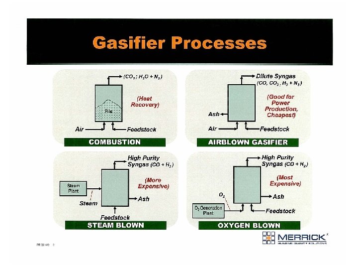
Process Equations Combustion with Oxygen: C + O 2 ↔ CO 2 Gasification with Oxygen: 2 C + O 2 ↔ 2 CO Gasification with Carbon Dioxide: C + CO 2 ↔ 2 CO Gasification with Steam: C + H 2 O ↔ CO + H 2 Gasification with Hydrogen: C + 2 H 2 ↔ CH 4 Water Gas Shift Reaction: CO + H 2 O ↔ H 2 + CO 2 Methanation Reaction: CO + 3 H 2 ↔ CH 4 + H 2 O
Syn. Gasifier Unique Equations NOx Emission Control: CO + NOx +H 2 O ↔ O 2 CNO + H 2 O 2 Reaction creates Nitroxyl reactive ions and hydrogen peroxide vapor which provides additional quench water purification and final Nitroxyl precipitation into water filters.
Syn. Gasifier Unique Equations Continued Sulfur Emission Control: CO + SOx +H 2 O ↔ O 2 CSO + H 2 O 2 Reaction creates Sulfinoxyl reactive ions and hydrogen peroxide vapor which provides additional quench water purification and final Sulfinoxyl precipitation into water filters.
Syn. Gasifier Unique Equations Continued Metals Emission Control: O-x + M ↔ MOx Ionized oxygen reaction creates metal oxides which are coagulated and precipitated into water filters.
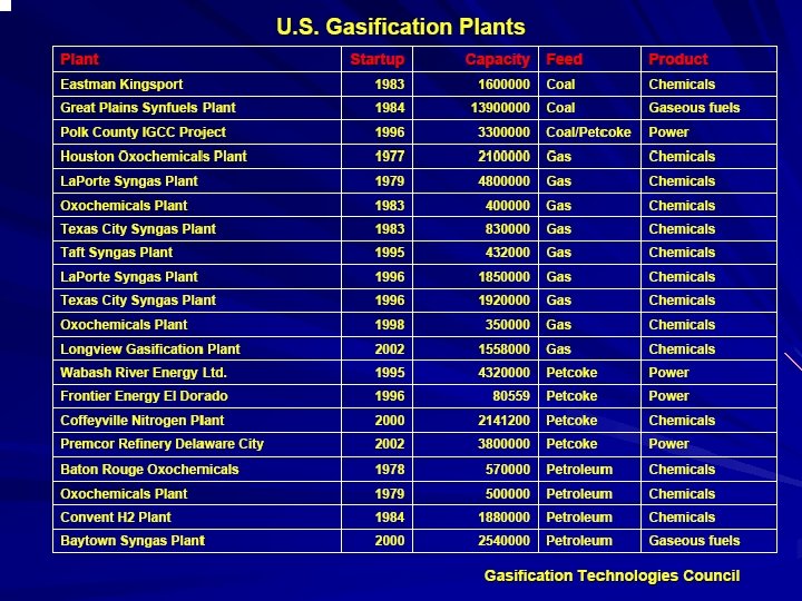
Major US Gasification System Vendors and Projects • E-GAS Conoco. Phillips – Upflow, wet fed (slurry) • GE Energy – Downflow, wet fed (slurry) • Shell Gasification – Upflow, dry fed • All use an entrained flow oxygen-blown system of gasification • Conoco. Phillips (Global Energy/PSI Wabash River) and GE Energy (Tampa Electric Polk Station) have demonstrated and proven technology in commercial scale IGCC plants
Comparison with Major Entrained Flow Gasifiers Technology Name/ Design Feature GE Energy (formerly Texaco) E-Gas (Conoco. Phillips) Shell Syn. Gasifier Feed System Coal in Water Slurry Dry coal, Lock Hopper & Pneumatic Conveying Dry (As Received) Coal, Air lock Drag Conveyor Gasifier Configuration Single Stage Downflow Two Stage Upflow Single Stage Upflow 4 Stage Horizontal Circular Flow Gasifier Wall Refractory Membrane Wall Inconel Pressure (psig) 500 -1000 Up to 600 80 Notes Offered as Quench or with Heat Recovery Currently only offered with Heat Recovery Quench Only Reference: Publication No. LFEE 2005 -002 WP MIT Laboratory for Energy and the Environment
Fischer Tropsch Liquid Fuels Process
The Fischer Tropsch Process
Tax Credits • Syn. Gas gasification projects can qualify for several tax credits: – Investment tax credits – Clean coal technology – Alternative fuels – Bio-mass conversion – Waste conversion – Job creation
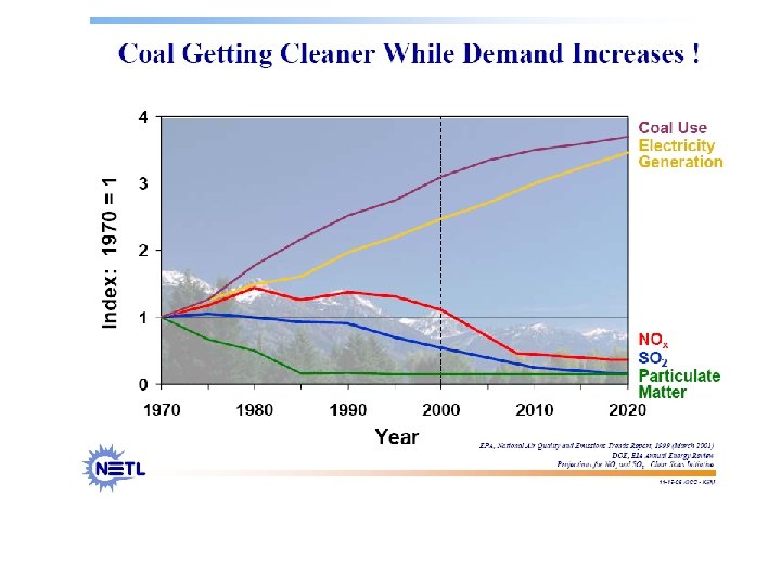
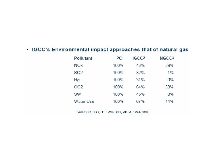
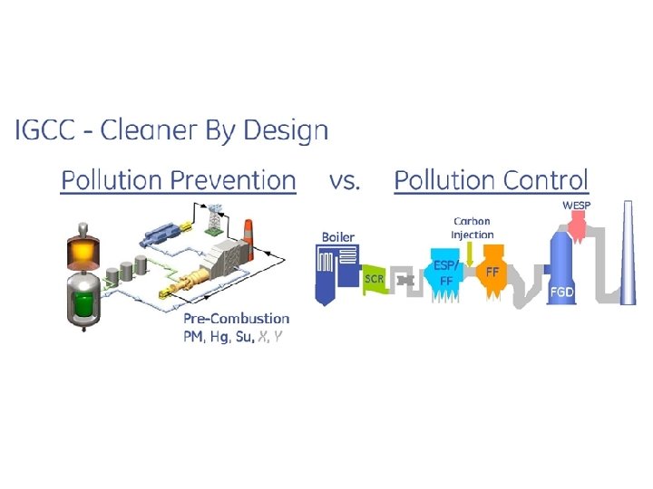
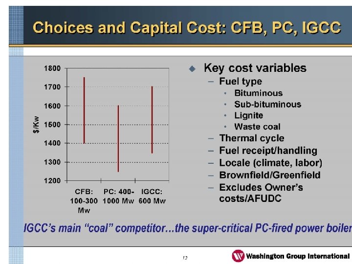
PC Emissions Improvements
IGCC Power Plant Mass Flow
Power Plant Efficiency is defined as the amount of electrical energy produced for sale as a fraction of the amount of fuel consumed in the process, expressed as a percentage. • • • Conventional – 32 to 37 % Supercritical – 35 to 43 % Ultra-supercritical – 45 % potential Circulating Fluidized Bed – 29 to 34 % IGCC (Integrated Gasification Combined Cycle) – 37 to 43 % with potential of 50 %
Electricity Flow, 2005 (Quadrillion Btu) 65. 1% 34. 9% 31. 3% http: //www. eia. doe. gov/emeu/aer/contents. html
Efficiency in Electricity Generation by Process www. umweltbundesamt. at/. . . /site/umweltthemen/industrie/IPPC_Konferenz/donnerstag_kraftwerke/6 -_Van_Aart. ppt
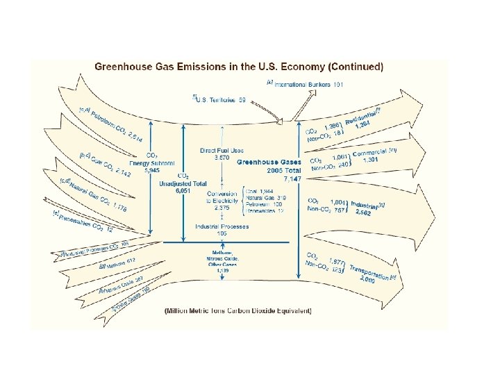
Greenhouse Gas Emissions
CO 2 Emission Sources
Bio. Mass Syn. Gas Flame