
SWMD ATF Damage Studies Beam Test George Ellwood
SWMD ATF Damage Studies Beam Test George Ellwood g. e. ellwood@rl. ac. uk
Overview of Talk • Introduction • Collimator Design • Purpose of Tests • Phase 1 Test • Locating Sample in Beam • Testing at ATF • Test Location • Diagnostics • Test Equipment 2
Introduction • At the ILC, the removal of halo particles having large amplitudes relative to the ideal orbit is mandatory; – to both minimize damage to both beam line elements and particle detectors – to achieve tolerable background levels in the latter. 3

Collimator Design • In the high energy, high intensity environment of the linear collider the low background levels will largely be ensured by placing a set of mechanical spoilers/absorbers very close to the beam. • The thin spoilers close to the beam line will scatter the halo particles. • These will then be absorbed downstream. 4
Problems with Spoiler/Absorber Collimators • This presents two significant problems: – (i) short-range transverse wakefields excited by these collimators may perturb beam motion and lead to both emittance dilution and amplification of position jitter at the IP. This aspect is being addressed by the T 480 experiments at SLAC ESA and modeling. – (ii) impact of even a small number of bunches at the expected energy densities can damage the spoilers. This is what we aim to test at ATF. 5
Testing • We would like to run two tests. • Phase 1 test to be run at ATF. – Damage studies test on a thin sample. – This test is aimed to give us experience working at ATF, and the use of systems needed for phase 2. • Phase 2 test to be run at ATF 2. – Shock wave studies test. 6
Purpose of Tests Phase 1 The purpose of the proposed first test run at ATF is to: • Allow us to commission the proposed test system of vacuum vessel, multi-axis mover, beam position and size monitoring. • Validate the mode of operation required for ATF in these tests. • Make simple measurements of the size of the damage region after individual beam impacts on the collimator test piece. – This will permit a direct validation of FLUKA/ANSYS simulations of properties of the materials under test. • Ensure that the radiation protection requirements can be satisfied before proceeding with a second phase proposal. 7

Purpose of Tests Phase 2 • Assuming a successful first phase test, the second stage of this proposal would be to measure the shock waves within the sample by studying the surface motion with a laserbased system, such as VISAR (or LDV), for single bunch and multiple bunches at approximate ILC bunch spacing. 8
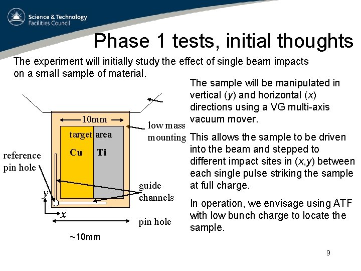
Phase 1 tests, initial thoughts The experiment will initially study the effect of single beam impacts on a small sample of material. The sample will be manipulated in vertical (y) and horizontal (x) directions using a VG multi-axis vacuum mover. 10 mm low mass target area mounting This allows the sample to be driven into the beam and stepped to Cu Ti reference different impact sites in (x, y) between pin hole each single pulse striking the sample at full charge. guide y channels In operation, we envisage using ATF x with low bunch charge to locate the pin hole sample. ~10 mm 9
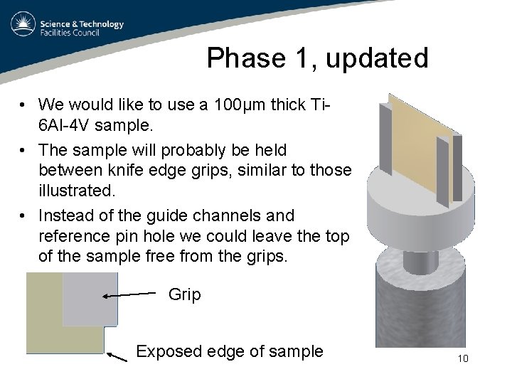
Phase 1, updated • We would like to use a 100µm thick Ti 6 Al-4 V sample. • The sample will probably be held between knife edge grips, similar to those illustrated. • Instead of the guide channels and reference pin hole we could leave the top of the sample free from the grips. Grip Exposed edge of sample 10
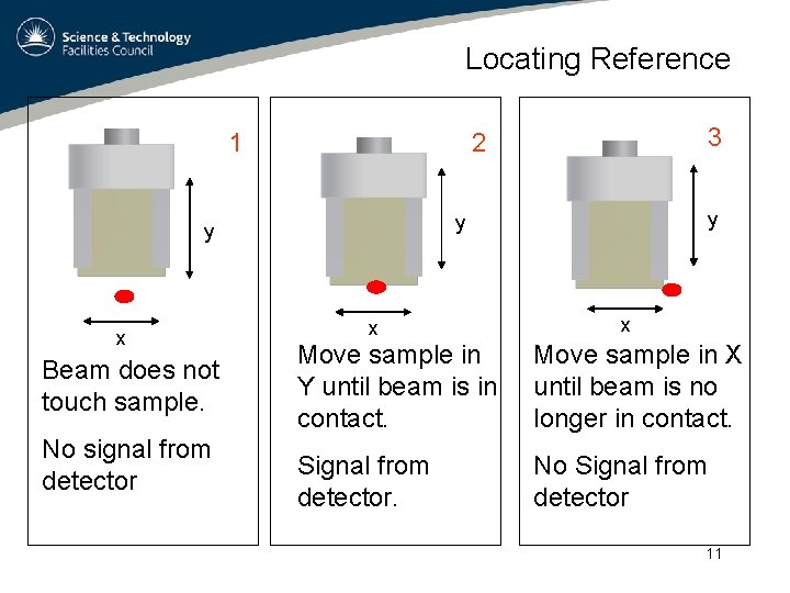
Locating Reference 1 Beam does not touch sample. No signal from detector y y y x 3 2 x x Move sample in Y until beam is in contact. Move sample in X until beam is no longer in contact. Signal from detector. No Signal from detector 11
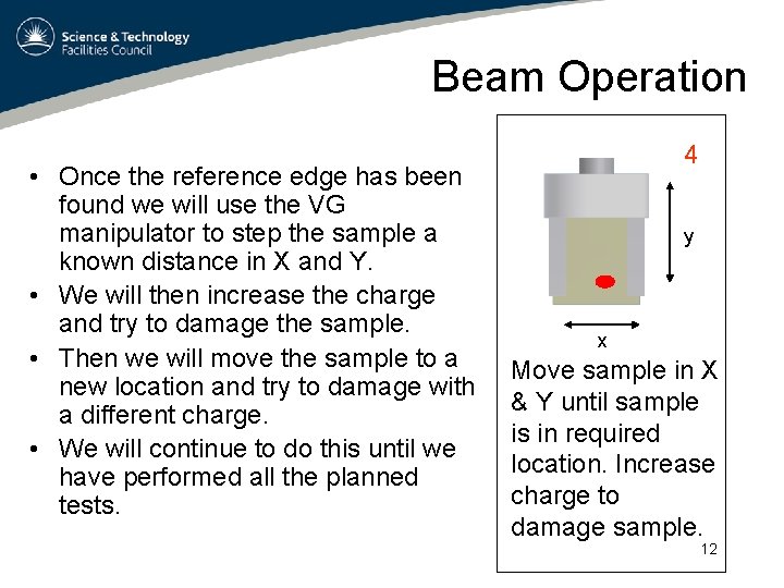
Beam Operation • Once the reference edge has been found we will use the VG manipulator to step the sample a known distance in X and Y. • We will then increase the charge and try to damage the sample. • Then we will move the sample to a new location and try to damage with a different charge. • We will continue to do this until we have performed all the planned tests. 4 y x Move sample in X & Y until sample is in required location. Increase charge to damage sample. 12
After test measurements • After testing we intend to measure the area of damage from each impact site with a Scanning Electron Microscope. • We will know the location of each damaged region because know the distance from the reference edge. • This will help validate our predictions on beam damage. 13
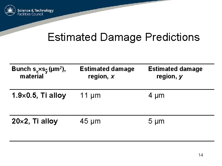
Estimated Damage Predictions Bunch sx s y (µm 2), material Estimated damage region, x Estimated damage region, y 1. 9 0. 5, Ti alloy 11 µm 4 µm 20 2, Ti alloy 45 µm 14
Radiation Levels Luis Fernandez has completed FLUKA simulations of energy deposited during testing at ATF. • Assuming a 20µm x 2µm square spot size. • 1. 28 Ge. V Beam energy Different thicknesses of Ti-6 Al-4 V and Cu were simulated. This was used to calculate the amount of energy absorbed by the various components involved in the test, as well as the radiation escaping the beam line into the ATF hall. This simulation does not take into account the effect of the downstream magnets on any shower products. 15
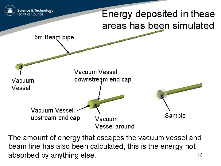
Energy deposited in these areas has been simulated 5 m Beam pipe Vacuum Vessel downstream end cap Vacuum Vessel upstream end cap Vacuum Vessel around Sample The amount of energy that escapes the vacuum vessel and beam line has also been calculated, this is the energy not 16 absorbed by anything else.
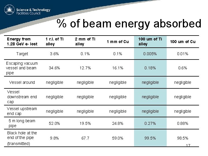
% of beam energy absorbed Energy from 1. 28 Ge. V e lost 1 r. l. of Ti alloy 2 mm of Ti alloy 1 mm of Cu 100 um of Ti alloy 100 um of Cu Target 3. 6% 0. 1% 0. 005% 0. 01% Escaping vacuum vessel and beam pipe 34. 6% 12. 7% 16. 1% 0. 18% 0. 6% Vessel around negligible negligible Vessel downstream end cap negligible negligible Vessel upstream end cap negligible negligible 5 m long beam pipe 52. 0% 19. 5% 24. 8% 0. 27% 0. 88% Black hole at the end of the pipe (transmitted) 9. 8% 67. 7 59. 0% 99. 5% 98. 5% 17
Testing at ATF 18
Location at ATF We have been offered two possible locations for the test. We would like to use location A. 19
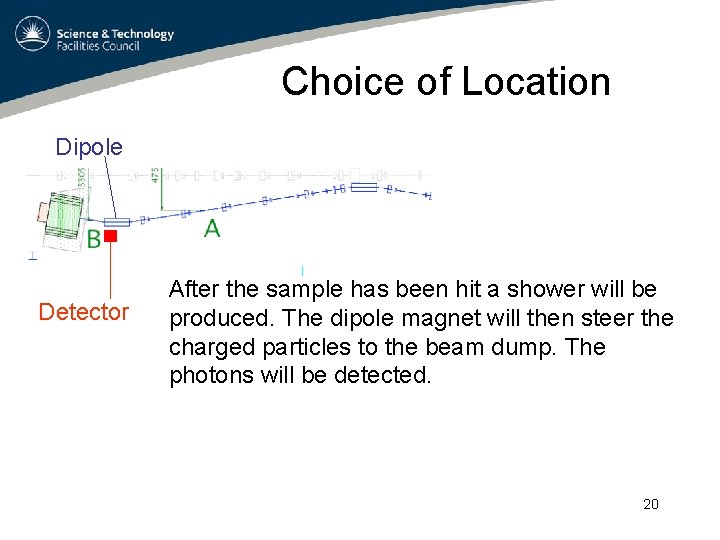
Choice of Location Dipole Detector After the sample has been hit a shower will be produced. The dipole magnet will then steer the charged particles to the beam dump. The photons will be detected. 20
Diagnostics • Upstream: – Wire Scanner – BPM • Downstream: – Photon Detector – BPM 21
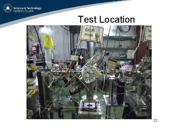
Test Location 22
Choice of Vacuum Vessel • It may be possible to use the Vacuum Vessel used for the ODR experiment. – This has the advantage that it is already positioned in the beam line and we could mount our manipulator directly on top. • Otherwise we could use our own vacuum vessel. – This would need a mechanical support to position in the beam line. – We will also have to align this vacuum vessel. 23
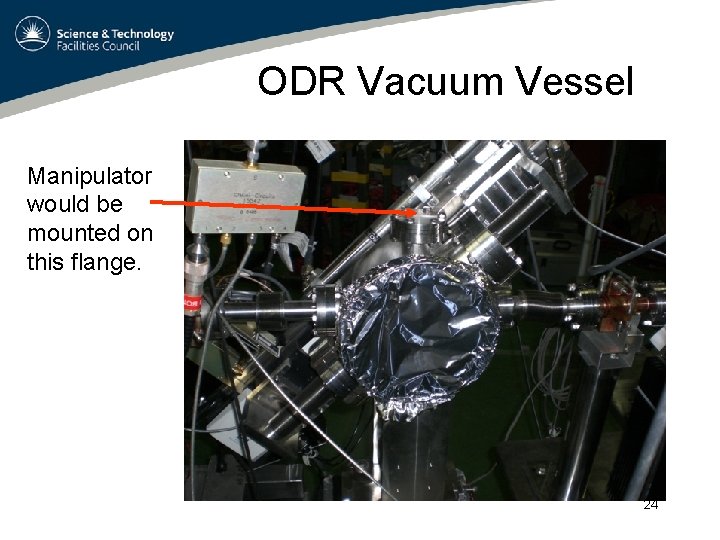
ODR Vacuum Vessel Manipulator would be mounted on this flange. 24
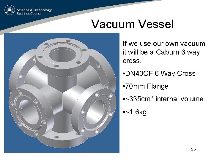
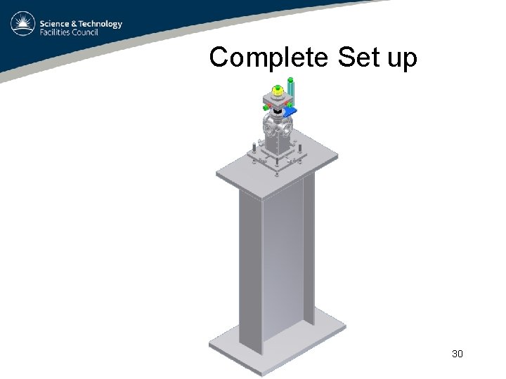
Vacuum Vessel If we use our own vacuum it will be a Caburn 6 way cross. • DN 40 CF 6 Way Cross • 70 mm Flange • ~335 cm 3 internal volume • ~1. 6 kg 25
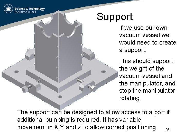
Support If we use our own vacuum vessel we would need to create a support. This should support the weight of the vacuum vessel and the manipulator, and stop the manipulator rotating. The support can be designed to allow access to a port if additional pumping is required. It has variable movement in X, Y and Z to allow correct positioning. 26
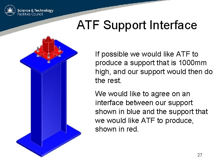
ATF Support Interface If possible we would like ATF to produce a support that is 1000 mm high, and our support would then do the rest. We would like to agree on an interface between our support shown in blue and the support that we would like ATF to produce, shown in red. 27
Manipulator • We are going to use a VG manipulator, as used by the Laserwire group. • Motorised in X, Z and rotation using Heason Stepper motors. • We will borrow the Laserwire group’s controller when available. 28
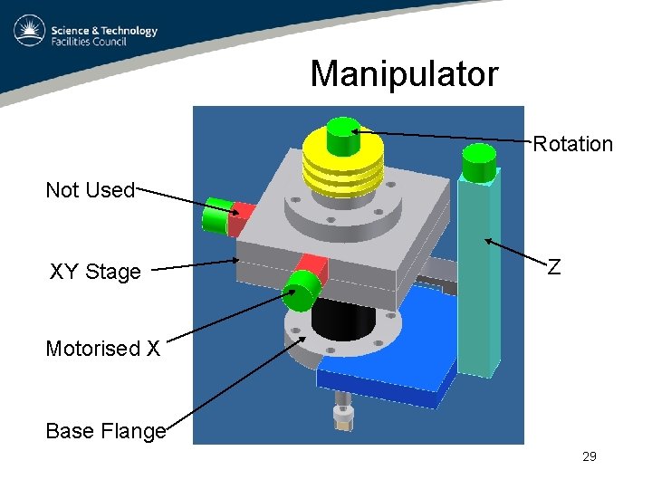
Manipulator Rotation Not Used XY Stage Z Motorised X Base Flange 29
Complete Set up 30

Summary • We would like to test at ATF and ATF 2 to validate our damage simulations. • We plan to do a two phase test. – Phase 1 to take place before 05/2008. – Phase 2 to take place when ATF 2 is available. • We would like to use the ODR experiment location. • We can use our own vacuum vessel or the vacuum vessel that was used by the ODR experiment. – We would like to decide this today. 31
- Slides: 31