
Switching and Forwarding Outline StoreandForward Switches Bridges and
Switching and Forwarding Outline Store-and-Forward Switches Bridges and Extended LANs Cell Switching Segmentation and Reassembly Spring 2003 CS 461 1
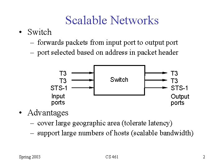
Scalable Networks • Switch – forwards packets from input port to output port – port selected based on address in packet header T 3 STS-1 Input ports Switch T 3 STS-1 Output ports • Advantages – cover large geographic area (tolerate latency) – support large numbers of hosts (scalable bandwidth) Spring 2003 CS 461 2
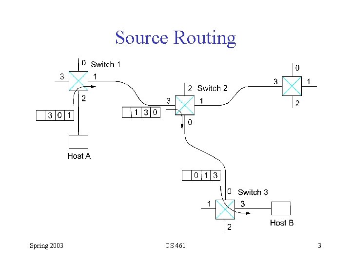
Source Routing Spring 2003 CS 461 3
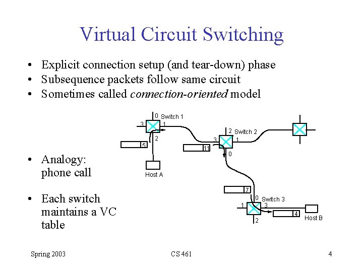
Virtual Circuit Switching • Explicit connection setup (and tear-down) phase • Subsequence packets follow same circuit • Sometimes called connection-oriented model 0 Switch 1 1 3 2 3 5 • Analogy: phone call 11 0 Host A 7 • Each switch maintains a VC table Spring 2003 2 Switch 2 1 1 0 Switch 3 3 2 CS 461 4 Host B 4
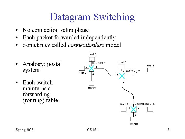
Datagram Switching • No connection setup phase • Each packet forwarded independently • Sometimes called connectionless model Host D • Analogy: postal system • Each switch maintains a forwarding (routing) table 3 Host C Host E 0 Switch 1 1 2 Host F 3 2 Switch 2 1 0 Host A Host G 1 0 Switch 3 Host B 3 2 Host H Spring 2003 CS 461 5
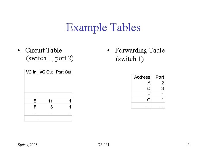
Example Tables • Circuit Table (switch 1, port 2) Spring 2003 • Forwarding Table (switch 1) CS 461 6
Virtual Circuit Model • Typically wait full RTT for connection setup before sending first data packet. • While the connection request contains the full address for destination, each data packet contains only a small identifier, making the per-packet header overhead small. • If a switch or a link in a connection fails, the connection is broken and a new one needs to be established. • Connection setup provides an opportunity to reserve resources. Spring 2003 CS 461 7
Datagram Model • There is no round trip delay waiting for connection setup; a host can send data as soon as it is ready. • Source host has no way of knowing if the network is capable of delivering a packet or if the destination host is even up. • Since packets are treated independently, it is possible to route around link and node failures. • Since every packet must carry the full address of the destination, the overhead per packet is higher than for the connection-oriented model. Spring 2003 CS 461 8
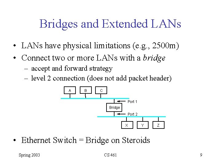
Bridges and Extended LANs • LANs have physical limitations (e. g. , 2500 m) • Connect two or more LANs with a bridge – accept and forward strategy – level 2 connection (does not add packet header) A B C Port 1 Bridge Port 2 X Y Z • Ethernet Switch = Bridge on Steroids Spring 2003 CS 461 9
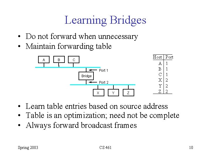
Learning Bridges • Do not forward when unnecessary • Maintain forwarding table A B C Port 1 Bridge Port 2 X Y Z Host A B C X Y Z Port 1 1 1 2 2 2 • Learn table entries based on source address • Table is an optimization; need not be complete • Always forward broadcast frames Spring 2003 CS 461 10
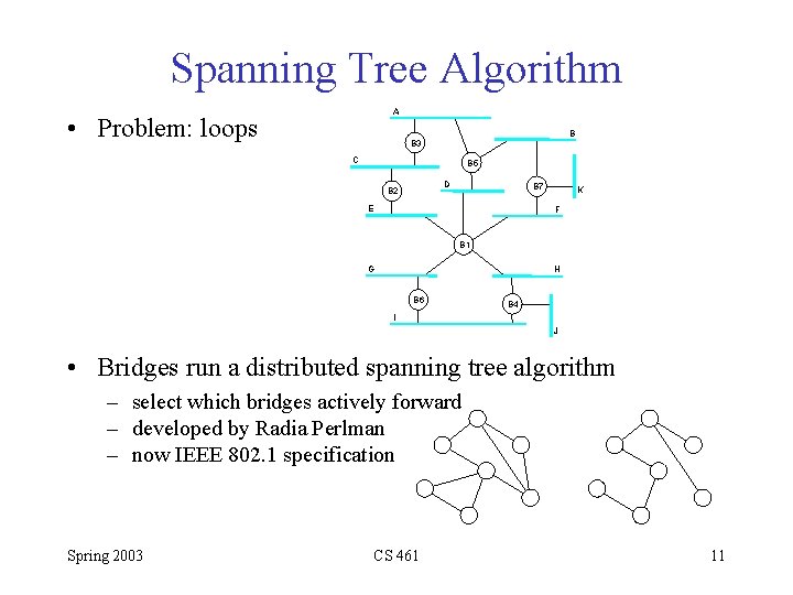
Spanning Tree Algorithm A • Problem: loops B B 3 C B 5 D B 2 B 7 E K F B 1 G H B 6 B 4 I J • Bridges run a distributed spanning tree algorithm – select which bridges actively forward – developed by Radia Perlman – now IEEE 802. 1 specification Spring 2003 CS 461 11
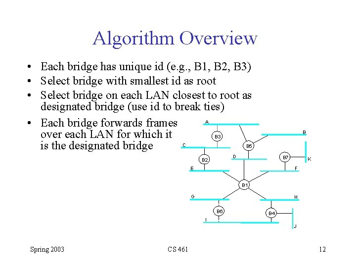
Algorithm Overview • Each bridge has unique id (e. g. , B 1, B 2, B 3) • Select bridge with smallest id as root • Select bridge on each LAN closest to root as designated bridge (use id to break ties) A • Each bridge forwards frames over each LAN for which it B 3 C B 5 is the designated bridge B D B 2 B 7 E K F B 1 G H B 6 B 4 I J Spring 2003 CS 461 12
Algorithm Details • Bridges exchange configuration messages – id for bridge sending the message – id for what the sending bridge believes to be root bridge – distance (hops) from sending bridge to root bridge • Each bridge records current best configuration message for each port • Initially, each bridge believes it is the root Spring 2003 CS 461 13
Algorithm Detail (cont) • When learn not root, stop generating config messages – in steady state, only root generates configuration messages • When learn not designated bridge, stop forwarding config messages – in steady state, only designated bridges forward config messages • Root continues to periodically send config messages • If any bridge does not receive config message after a period of time, it starts generating config messages claiming to be the root Spring 2003 CS 461 14
Broadcast and Multicast • Forward all broadcast/multicast frames – current practice • Learn when no group members downstream • Accomplished by having each member of group G send a frame to bridge multicast address with G in source field Spring 2003 CS 461 15
Limitations of Bridges • Do not scale – spanning tree algorithm does not scale – broadcast does not scale • Do not accommodate heterogeneity • Caution: beware of transparency Spring 2003 CS 461 16
Cell Switching (ATM) • • • Connection-oriented packet-switched network Used in both WAN and LAN settings Signaling (connection setup) Protocol: Q. 2931 Specified by ATM forum Packets are called cells – 5 -byte header + 48 -byte payload • Commonly transmitted over SONET – other physical layers possible Spring 2003 CS 461 17
Variable vs Fixed-Length Packets • No Optimal Length – if small: high header-to-data overhead – if large: low utilization for small messages • Fixed-Length Easier to Switch in Hardware – simpler – enables parallelism Spring 2003 CS 461 18
Big vs Small Packets • Small Improves Queue behavior – finer-grained preemption point for scheduling link • • • maximum packet = 4 KB link speed = 100 Mbps transmission time = 4096 x 8/100 = 327. 68 us high priority packet may sit in the queue 327. 68 us in contrast, 53 x 8/100 = 4. 24 us for ATM – near cut-through behavior • • • Spring 2003 two 4 KB packets arrive at same time link idle for 327. 68 us while both arrive at end of 327. 68 us, still have 8 KB to transmit in contrast, can transmit first cell after 4. 24 us at end of 327. 68 us, just over 4 KB left in queue CS 461 19
Big vs Small (cont) • Small Improves Latency (for voice) – – voice digitally encoded at 64 KBps (8 -bit samples at 8 KHz) need full cell’s worth of samples before sending cell example: 1000 -byte cells implies 125 ms per cell (too long) smaller latency implies no need for echo cancellers • ATM Compromise: 48 bytes = (32+64)/2 Spring 2003 CS 461 20
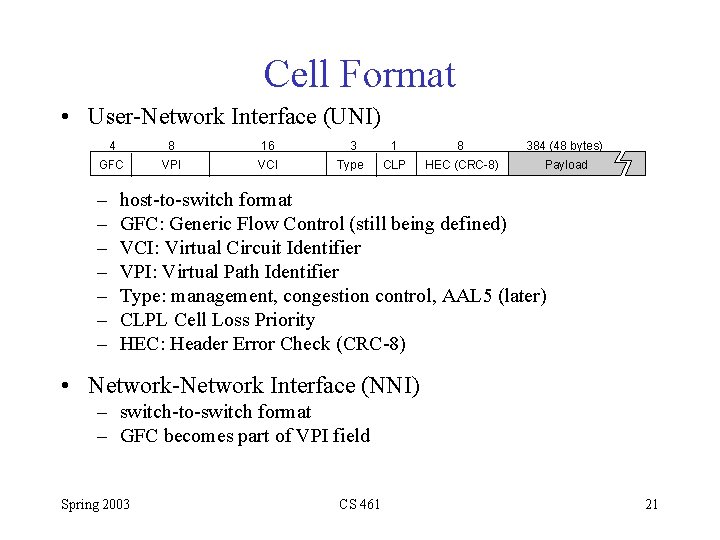
Cell Format • User-Network Interface (UNI) 4 8 16 3 1 8 384 (48 bytes) GFC VPI VCI Type CLP HEC (CRC-8) Payload – – – – host-to-switch format GFC: Generic Flow Control (still being defined) VCI: Virtual Circuit Identifier VPI: Virtual Path Identifier Type: management, congestion control, AAL 5 (later) CLPL Cell Loss Priority HEC: Header Error Check (CRC-8) • Network-Network Interface (NNI) – switch-to-switch format – GFC becomes part of VPI field Spring 2003 CS 461 21
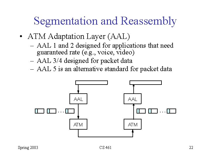
Segmentation and Reassembly • ATM Adaptation Layer (AAL) – AAL 1 and 2 designed for applications that need guaranteed rate (e. g. , voice, video) – AAL 3/4 designed for packet data – AAL 5 is an alternative standard for packet data AAL … … ATM Spring 2003 ATM CS 461 22
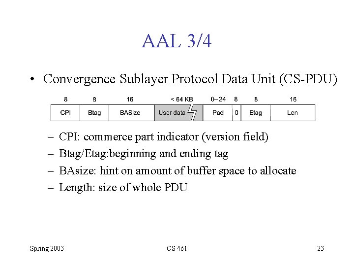
AAL 3/4 • Convergence Sublayer Protocol Data Unit (CS-PDU) – – CPI: commerce part indicator (version field) Btag/Etag: beginning and ending tag BAsize: hint on amount of buffer space to allocate Length: size of whole PDU Spring 2003 CS 461 23
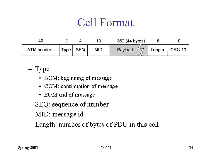
Cell Format – Type • BOM: beginning of message • COM: continuation of message • EOM end of message – SEQ: sequence of number – MID: message id – Length: number of bytes of PDU in this cell Spring 2003 CS 461 24
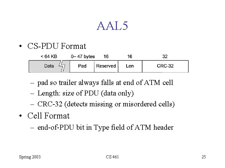
AAL 5 • CS-PDU Format – pad so trailer always falls at end of ATM cell – Length: size of PDU (data only) – CRC-32 (detects missing or misordered cells) • Cell Format – end-of-PDU bit in Type field of ATM header Spring 2003 CS 461 25
- Slides: 25