SVC Based Flexible AC Transmission System FACTS Prepared
 Prepared by : Thana’ Hamdan Hiba Jad-Allah")
SVC Based Flexible AC Transmission System (FACTS) Prepared by : Thana’ Hamdan Hiba Jad-Allah Supervised by: Dr. Kamel Saleh

content: �Why PF correction �Ordinary methods of PF correction �Static variable compensation method and its advantages �Methodology and Simulation of SVC �Close loop control �PF meter �Matlab simulation of the project �Result of matlab simulation �Zero crossing and result on hardwire

• Why PF correction ?

• Why PF correction ? �Until these goals are achieved : �Increase transmission efficiency �Increase voltage regulation �Reducing an apparent power (S) leads to reducing current �Reducing losses of electrical energy �Saving both of money and energy

• Methods of PF correction 1 - Capacitor banks The main disadvantage of this method is that it requires high load to sense the change on the power factor and its changes in a steps and not in smooth way , so it can’t be achieved a PF at some load 2 - Synchronous Condenser The main disadvantage of using this method is the high cost to be used in light load 3 - Phase Advancer : The main Disadvantage is that Using Phase advancer is not economical for motors below 200 H. P

• Static variable compensation method and its advantages � SVCs are part of the Flexible AC transmission system device family. This method uses only one capacitor bank and we control the PF by injected reactive power into the line other than controlling capacitance value.

Advantages of using SVC method: �Improved system transient and steady-state stability �Improved static and dynamic load � One capacitor bank only used �Cheaper than other methods �Reduced transmission losses �Simple controlling units
 based")
• Methodology and Simulation of SVC �SVC uses TSC (Thyristor Switched Capacitors) based on shunt compensation to controls the power flow in transmission system and improves the transient stability of power grids. * shunt compensation:

• Methodology and Simulation of SVC �Triac: �consists of two thyristors connected in inverse parallel , and this The most important part in this method, where we get the variable voltage by controlling the value of the firing angle

• Methodology and Simulation of SVC �This branch is parallel to the load and contributes the generator in supplying the load by reactive power

• Close loop control the PF meter designed by using Matlab Simulink to measure the load factor, the measured value is then entered on a MC to be compared with a selected reference value , and through a closed loop improves the load PF to be equal to the reference value

• PF meter : �To calculate the PF, we must first calculate the time difference between the two signals and convert it to the PF , as shown figure - next slide according this equation:

• PF meter:

• Matlab simulation of the project

• PF meter �Zero Crossing Detector: The zero cross detection is a circuit that gives a pulse as indication when the input voltage waveform crosses the zero axis. and this is the first step to design PF meter.

�The circuit of zero crossing on hardware :

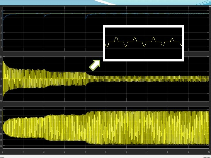
The result of zero crossing on hardware :

- Slides: 19