Suspension Systems Frames Two types ladder and unibody
 § Ladder • Separate")
Suspension Systems § Frames § Two types (ladder and unibody) § Ladder • Separate body/frame • Body bolted to frame • Separated by body mounts with rubber insulators

Suspension Systems § Springs are used to support the vehicle and cushion the passenger from road bumps. • Springs come in many different materials and styles, even pneumatic. § Leaf springs • Semi-elliptical is the only leaf type in common use
 • Bushing - rubber usually in front •")
Suspension Systems § Mounting (leaf spring) • Bushing - rubber usually in front • Shackle - permits spring to change lengths • U-bolts

Suspension Systems §Leaf spring parts • Leaves • Center bolt • Eye • Rebound clip • Leaf pad

Suspension Systems § Coil • Spring wire heated and wound into coil • Insulator pads used between frame and spring • Ends of coils are shaped to fit application

Suspension Systems § Torsion bar • Straight spring steel bar

Suspension Systems § Air suspension systems • Air spring, diaphragm, and plunger • Some vehicles use air bags • Conventional springs are replaced by four air bags or air spring assemblies to support the vehicle and control its height • Air pump to supplies compressed air • Control and leveling valves will be at each wheel • Devices will control height and ride of vehicle either by driver command and/or automatically through computer

Suspension Systems § Shocks are velocity sensitive • Faster pump rate means more resistance • Creates heat • Aerates fluid, creating foam § Gas-charged shocks minimize fluid aeration • Works like pressure cooker § Internal piston uses spring-loaded metering valve and orifices to control fluid flow • Second valve controls fluid flow to outer tube - double tube type (reservoir) § May use defecting valve for oil control (single tube or double tube type)

Suspension Systems § Coil-over Shock § Aftermarket design to replace OEM equipment
 with coil spring")
Suspension Systems § Load Levelers § Shock usually heavy-duty (extra-firm damping) with coil spring added § Compensates for heavier loads

Suspension Systems § Air Shock § Same concept as load levelers, except an air chamber is used to provide extra spring force • Extra spring capacity varies by air pressure

Suspension Systems § Gas Shock § Charged with nitrogen gas § Prevents fluid foaming § Reduces lag time - quick shock response § Controls even the smallest movement § Self-adjusting § Improves cornering, braking, and acceleration stability

Suspension Systems § Variable Damping Shock § Both manually adjustable or electrically adjustable are available § Manual damping changes may be through external knob • May require removal of shock • May require disassembly of shock

Suspension Systems § Newest shocks use a magnetic fluid which can change damping effect in milliseconds • (Magneto Rheological fluid) § Another newer style self-adjusts to damp firmly on smooth roads, but lightly on rough roads • Examples include the Edlebrock IAS and the Bose Suspension System

Suspension Systems § Front Suspension Systems § A front suspension system must allow up and down movement of wheels while also allowing the wheels to be turned. § The suspension system must also hold the alignment angles for proper handling, steering, and tire wear. § Two types • Solid axle or independent (live or dead)

Suspension Systems § Solid Axle Suspension § This system only has limited use in light trucks but is used in almost all heavy trucks § Chrysler and Jeep are the last big users in light truck market

Suspension Systems § Independent Front Suspension § Twin I-beam front suspension • Each front wheel is supported at the end of a separate beam axle • Wheel end uses king pins or ball joints to allow steering knuckle to pivot • Opposite ends of each beam axle are attached to frame through flexible pivot • Coil springs provide suspension • Radius arms prevent backward or forward movement of axle
 Suspension § Bottom longer § Top shorter §")
Suspension Systems § Short/Long Arm (SLA) Suspension § Bottom longer § Top shorter § Reduces track change - tire scrub § Allows the wheel to tilt inward at the top to keep the vehicle tracking constant § May have spring on upper or lower control arm
 control arm • Mounting with bushings")
Suspension Systems § SLA Parts § Short (upper) control arm • Mounting with bushings and cross shaft • Some vehicles may use eccentric bolts on upper or lower control arms to make adjustments for alignment Perform caster & camber adjustments
 control arm • Bushing shaft")
Suspension Systems § Long (lower) control arm • Bushing shaft

Suspension Systems § Bushing - a sleeve that allows a controlled amount of movement to take place between a moveable part and a stationary one without causing wear • Bushings are used in many places • Worn bushings will cause suspension problems • Inspect bushing visually for cracked rubber, being off-center, distorted, or missing • Shiny area on shaft indicates movement Warning: Do not distort control arm when removing or installing control arm bushing.

Suspension Systems § Suspension Pivot Inspection § Ball joints • A socket type joint that allows turning while moving through an arc • Found on at least one end of steering knuckle • Worn ball joints will cause erratic steering, free play, tire wear, and noise

Suspension Systems § Ball joint • Used as pivot point for steering • May be follower or load carrying ball joint • Ball joint that receives force from the spring is a load carrying ball joint
 connects other end of knuckle")
Suspension Systems • The follower (non-load carrying ball joint) connects other end of knuckle to other control arm. • Some ball joints have a wear indicator, including a grease zerk, which can be used to determine joint life.

Suspension Systems § Jounce and rebound bumpers • Prevents control arms from contacting frame • If smashed - indicates weak springs, bad shocks or continuous overloading of vehicle

Suspension Systems § Strut rod § Stabilizes single point lower control arm § May provide caster adjustment

Suspension Systems § Mc. Pherson Strut § Used on most new vehicles § Upper control arm replaced by strut assembly which contains bearing, shock absorber, and pivot point § Coil spring on strut is most common § Shock absorber will be either integral with strut or replaceable cartridge § Spindle now has only one ball joint (lower/follower) § Steering arm may be part of spindle or part of strut

Suspension Systems § Modified Mc. Pherson Strut § Coil spring has been moved to lower control arm § Easier strut replacement § Lower ball joint is now load carrying type

Suspension Systems § Strut/SLA Suspension § Uses unequal length A-arms § Uses strut which does not pivot with steering knuckle § Gives steering geometry of SLA § The lower ball joint is the load carrying ball joint
 • § Leaf spring")
Suspension Systems § Rear Suspension § Solid (live or dead) • § Leaf spring suspension • § May use leaf springs, coils, torsion bars, or air bags Leaf springs provide both axle location and torque transfer Coil springs require control arms for location and torque transfer • • Usually two lower and one or two upper Uppers either angled or a track (panhard) rod used for lateral location

Suspension Systems § Torque tube or arm with coil springs • Springs provide only suspension not location • Torque tube or arm transfers driving and braking torque to the chassis • Control arms and/or a track (panhard) rod provide axle location

Suspension Systems § Independent • May use coils, transverse leaf, struts, or torsion bars • If live axle, differential is mounted to frame with half shafts to the rear hubs • Control arms are of various styles or multi-link design

Suspension Systems § Stabilizer Bars § Stabilizer bars, also called sway bars, provide a lateral link between the suspension on each side of a vehicle § This is a torsion bar that provides a counteracting force to the body during a turn to limit body lean on sway § This attempts to keep the vehicle more level during turns § May be used in front or both front and rear § Will change handling characteristics § Sway bars will not effect ride height

Suspension Systems § All suspension modifications will affect handling Warning: While changes to suspension systems can void warranties and may cause unsafe handling, if done properly, they can improve handling. Caution: All modifications should be looked at carefully for safety.

Suspension Systems § Lubrication of Suspension Parts § Grease fitting provided when required § Use of Teflon® and special greases § Do not grease rubber • Will destroy rubber § Some of latest bushings contain own lubricant • These do not require lubrication throughout life
")
Suspension Systems § Suspension Component Replacement § Follow manufacturer (both vehicle and replacement component) recommendations for tools and methods § Safety must be observed • Springs store lethal force • You are usually working under vehicle to perform these operations Warning: The force needed to remove and replace suspension components can crush you.

Suspension Systems § Torque specifications are critical § Suspension parts should not fall off § After work is completed, alignment will need to be checked and vehicle road tested.

Steering Systems § Rack and Pinion Linkage § Rack and pinion linkage does not use Pitman and idler arms or centerlink § Rack and pinion may mount: • On frame/cradle (front steer and rear steer) • On bulkhead § Bellows allow linkage to exit rack without allowing dirt in • Check for holes or cuts in boot – replace boot if bad • Oil or grease may be in boot, but are not always a sign of a leaking system
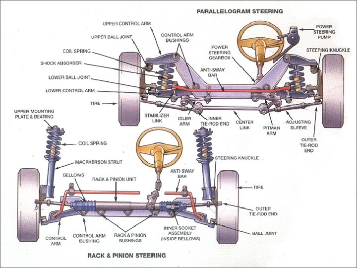

Steering Systems § Parallelogram Linkage

Steering Systems § Steering Linkage § Cross steering • Used with solid axle

Steering Systems § Haltenberger • Used with Ford Twin I-Beam

Wheel Alignment § What is Wheel Alignment? § Balance of steering angles § Provides correct relationship between caster, camber, ball joint inclination, toe-in, and turning radius

Wheel Alignment § Alignment
")
Pre-Alignment Inspection § Road test for: § § § § Pull Shake Shimmy (vibration) Steering wheel centered Steering wheel returns to center after turn Tire and bearing noises Scraping noises on sharp turns (may indicate wrong tire size) § Noise (clunks) in suspension

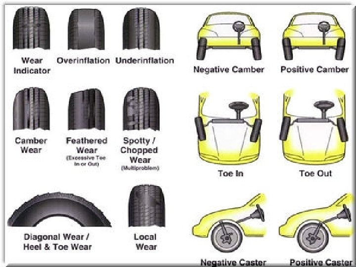
Pre-Alignment Inspection § Inspect tires for: § § § § § Underinflation (wearing outer sections) Overinflation (wearing center section) Wearing inside of tire (toe-out or negative camber) Wearing outside of tire (toe-in or positive camber) Ply separation (bulges or uneven tread) Cuts, bruises or nails Same size tires on all wheels Right size tires on vehicle Best tires mounted on front (most accurate alignment)

Pre-Alignment Inspection § Inspect springs/torsion bars for: § Broken, sagged, or weak parts (rebound bumpers broken or damaged) § Damage to front and rear air springs § Damage to connecting hoses (air springs) and hardware § Correct hose routing § Leaking connections § Air spring compressor operation, including connecting hoses and fittings § Air ride (suspension) control modules (proper connections and damaged wiring)

Pre-Alignment Inspection § Proper ride height § Air ride height sensor damage or missing connecting hardware

Pre-Alignment Inspection § Inspect front and rear shocks or struts for: § Leakage § Physical damage (dented, bent) § Loose mounting (rubber bushings missing or damaged) § Broken brackets § Torn boots § Looseness, damage, or binding in upper strut § Excessive play in upper strut bearing

Pre-Alignment Inspection § Inspect ball joints § Follow proper procedures to unload joints and check for axial and radial play § Inspect control arms for: § Damaged (cracked) or missing bushings

Pre-Alignment Inspection § Inspect kingpin for: § § § End play in bushings Missing end caps Locating pins missing Seized kingpins Refusal to take grease § Check steering knuckle for damage

Pre-Alignment Inspection § Inspect strut rod bushings for: § Missing or damaged bushings § excessive movement § Heat damage from catalytic converter or exhaust (rear mounted type) § Missing heat shields

Pre-Alignment Inspection § Inspect stabilizer bar links or mounts for: § Broken or missing mounts at frame § Damaged bushings on lower control arm § Missing rubber bushings on sway bar links

Pre-Alignment Inspection § Inspect the gear box for: § Looseness in the Pitman arm (joint) § Tightness of the mounting box § Free play in gear box (preload adjustment) • Adjust sector shaft if necessary according to OEM procedures § Damage to steering shaft coupler or U-joint § Looseness and leakage of power steering control valve
 § Check OEM specifications")
Pre-Alignment Inspection § Idler arm play (up and down movement) § Check OEM specifications with 25 lbs. of force § Check idler arm mounting to frame for looseness
 for: § No side to")
Pre-Alignment Inspection § Inspect tie rods (inner and outer) for: § No side to side movement § Ability to rotate (test by grabbing tie rod and twisting) § Cotter pins on castellated nuts § Inspect the linkage (both center link and drag link) for: § Damage § Looseness § Missing attaching hardware

Pre-Alignment Inspection § Inspect rear suspension for: § Worn bushings (control arms, strut rods, track bars) § Missing rebound bumpers § Loose upper and lower ball joints § Damaged or missing upper and lower control arm bushings § Clash marks on springs § Broken leaves on leaf springs

Pre-Alignment Inspection § Inspect the steering rack for: § Worn mount bushings • Rack housing should not move back and forth • If worn, may result in lack of stability and/or shimmy § Looseness and play in inner tie rod ends (ball and socket) and outer tie rod ends § Torn rack and pinion bellows • If torn, lubricant will leak out and dirt will enter § Binding or hard steering § Looseness in the rack and pinion unit

Pre-Alignment Inspection § Inspect wheel bearings for: § Looseness § Noise § Inspect the frame for: § Bent subframes § Missing fasteners § Collision damage (bent components)

Wheel Alignment § Steering Angles § Affect tread wear, steering, and handling § Designed into the chassis and suspension by the manufacturer § Some are adjustable, others may not be § Angles that are not adjustable can only be corrected by replacing bent or worn components
 or")
Wheel Alignment § Camber § Tire wear angle § Camber is inward (negative) or outward (positive) tilt of wheel at top § Excessive positive wears outside edge § Excessive negative wears inside edge

Wheel Alignment § Camber brings tire contact patch more nearly under point of load § Provides easier steering by having weight correctly distributed over the wheel bearings § Incorrect camber will cause: • Excessive wear to ball joints and wheel bearings • Excessive wear to one side of tire tread • Vehicle to pull to one side

Wheel Alignment § Caster § Directional stability angle § Caster is the forward or backward angle of steering axis (ball joints, struts, or kingpins) • Forward tilt is called negative caster • Backward tilt is called positive caster § Caster gives front wheels tendency to maintain straight-ahead position • Establishes a lead point for wheels to follow

Wheel Alignment § Incorrect caster will cause: • • • Pulling to side with most negative (-) caster Wander and weave (negative caster) Instability at high speeds (negative caster) Hard steering (positive caster) Excessive road shock and shimmy (most common positive caster) § Lead for road crown (optional) • Right side may be a little more positive (1/4” to 1/2”) than left

Wheel Alignment § Toe § Most critical tire wearing alignment factor § Difference in distance between front of front tires and rear of front tires • Measured in inches (or millimeters) at front and rear of tires at same height • Can be positive (toe-in) or negative (toe-out) § Correct toe prevents side scuffing of tires while vehicle is in motion
")
Wheel Alignment § Designed to give 0° when vehicle is in motion (running toe) § Incorrect toe feathers tire § 4 -wheel alignment requires toe checks at both ends of vehicle § Toe is also directional control angle • If incorrect, can cause wander or shimmy

Wheel Alignment § Toe-out on turns is the relative toe setting of the front wheels, as they turn to left, or right. § When a vehicle makes a turn, each wheel should rotate with true rolling motion, that is free from tire scrub.

Wheel Alignment § True rolling motion is only obtained when each wheel is at 90 degrees to a line drawn between the swivel axis and the center of turn. § Because the rear wheels are fixed, the center of turn will lie somewhere along the centerline of the rear axle, depending on how far the steering wheel is turned from the straight-ahead position.

Wheel Alignment § To provide true rolling motion, the inner wheel must be turned through a greater angle than the outer wheel. This allows the inner wheel to turn through a smaller turning radius than the outer wheel. § This automatically correct alignment is obtained by use of the Ackerman principle and layout. With the steering linkage at the rear of the wheels,

Wheel Alignment § the distance across the tie-rod ends, at the steering arm joints, is made shorter than the distance across the steering axis swivels. This forces the inner wheel to turn through a larger angle when the steering is turned. § The Ackerman angle is the angle the steering arms make with the swivels, on the centerline of the vehicle, at or near the center of the rear axle.

Wheel Alignment § Scrub radius is also known as steering offset, and scrub geometry. It is the distance between 2 imaginary points on the road surface - the point of center contact between the road surface and the tire, and the point where the steering-axis center-line contacts the road surface. § If these two points intersect at the center of the tire, at the road surface, then the scrub radius is zero.

Wheel Alignment § If they intersect below the road surface, scrub radius is positive. § If they intersect above the road surface, scrub radius is negative. § The effect of scrub radius - positive or negative - is to provide a turning moment which attempts to turn the wheel away from the central position, when the vehicle is in motion.

Wheel Alignment § On a rear-wheel-drive vehicle with positive scrub radius, the vehicle’s forward motion and the friction between the tire and the road causes a force which tends to move the front wheels back. This would cause the wheels to toe-out. § If it has negative scrub radius, the front wheels again tend to move back, but this time, they toe-in.

Wheel Alignment § On front-wheel-drive vehicles, the opposite occurs. Positive scrub radius causes toein, and negative causes toe-out. § During braking, on any type of drive, if braking effort is greater on one side of the vehicle than the other, positive scrub radius will cause the vehicle to veer towards the side with the greater effort.

Wheel Alignment § Negative scrub radius will cause the vehicle to veer away from the side of greatest effort. How much it veers depends on the size of the scrub radius. § This is why, vehicles with a diagonal-split brake system have negative scrub radius built into the steering geometry. If one half of the brake system fails, then the vehicle will tend to pull up in a straight line.

Wheel Alignment § Since the offset of the wheel rim determines where the centerline of the tire meets the road surface, it is important that the offset is not changed if wheels are being replaced. § Changing the rim offset changes the scrub radius, and also the predictability of the vehicle handling, if brakes

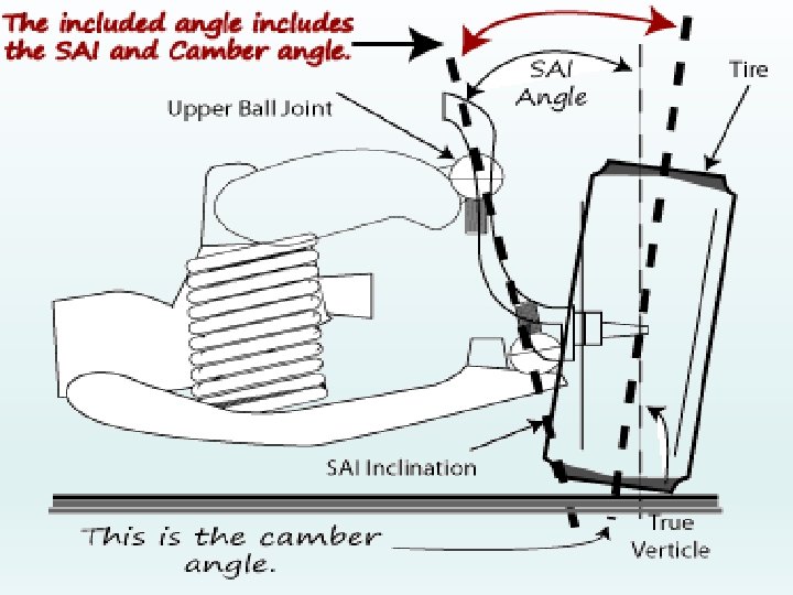
Wheel Alignment § The axis around which the wheel assembly swivels as it turns to the right or left is called the steering axis. It is formed by drawing a line through the upper and lower pivot points of the suspension assembly. Seen from the front of the car, it is tilted inward.

Wheel Alignment § The angle formed between this line and the vertical, provides steering axis inclination angles. § Steering axis inclination acts, with caster, to provide a self-centering of the front wheels.

Wheel Alignment § When the wheels are in the straightahead position, the ends of the stub axles are almost horizontal. § When the wheels turn to either side, the effect of steering axis inclination is to make the ends of the stub axle tend to move downward, but this is prevented by the wheel. The stub axle carrier then must move up, which raises the front of the vehicle.

Wheel Alignment § When the steering wheel is released, the mass of the vehicle forces the stub carrier back down, which pushes the wheels back to a central position. § With a vertical steering axis, no selfcentering would occur. The wheel would pivot on a radius with the steering axis as its center.

Wheel Alignment § This would introduce a turning moment on the wheel, road shocks would be transmitted back to the steering wheel, and steering would be difficult to control.

Wheel Alignment § Steering axis inclination brings the pivot point close to the center of the tire contact patch at the road surface. It intersects with the camber line drawn through the tire and the wheel. § If these 2 lines intersect at the center of the tire, at the road surface, then the vehicle is said to have zero offset, or zero scrub radius.

Wheel Alignment § If they intersect below the road surface, then it has positive offset or scrub radius. § If they intersect above the road surface, then it has negative offset or scrub radius. § The angle between the steering axis inclination and the camber line is called the included angle. It is a diagnostic angle.

Wheel Alignment § Since the steering axis inclination is not adjustable, if the camber angle is correct, then the steering axis inclination should also be correct, that is it should match the specification.

Wheel Alignment § Turning radius is a measure of the vehicles turning circle when the steering wheel is turned to its limit.

Wheel Alignment § The thrust angle refers to all four wheels and their relationship to each other and to an imaginary centerline that runs from each pair of wheels down the center of the vehicle. The term 'thrust line' refers to the direction in which the rear wheels are pointing.
- Slides: 88