Surveying Prof Rajesh Bhagat Asst Professor CED YCCE
")
Surveying Prof. Rajesh Bhagat Asst. Professor, CED, YCCE, Nagpur B. E. (Civil Engg. ) GCOE, Amravati M. Tech. (Enviro. Engg. ) VNIT, Nagpur Experience & Achievement: v Selected Scientist, NEERI-CSIR, Govt. of India. v GATE Qualified Three Times. v UGC-NET Qualified in First Attempt. v Selected Junior Engineer, ZP Washim. v Three Times Selected as UGC Approved Assistant Professor. v Assistant Professor, PCE, Nagpur. v Assistant Professor, Cummins College of Engg. For Women, Nagpur v Topper of Pre-Ph. D Course Work at UGC-HRDC, RTMNU Nagpur Mobile No. : - 8483002277 / 8483003474 Email ID : - rajeysh 7 bhagat@gmail. com Website: - www. rajeysh 7 bhagat. wordpress. com
 Introduction: Chain and Compass Traversing. 2) Classification, division of survey, principle of")
UNIT-I 1) Introduction: Chain and Compass Traversing. 2) Classification, division of survey, principle of survey, chain surveying, basics, direct ranging and cross staff survey. 3) Compass Surveying: Prismatic compass, true and magnetic bearing, local attraction, Compass traversing. 2
 Direct Leveling: Leveling, study of dumpy level, temporary adjustments, principles")
UNIT - II 1) Direct Leveling: Leveling, study of dumpy level, temporary adjustments, principles of leveling, reduction of levels, classification of leveling & reciprocal leveling. 2) Curvature, refraction corrections & reciprocal leveling. 3
 Contouring: Characteristics, uses, and methods of locating contours & interpolation")
UNIT – III 1) Contouring: Characteristics, uses, and methods of locating contours & interpolation of contours. 2) Trignometrical Leveling: Indirect leveling, elevation of a point with base of an object accessible and inaccessible (with instrument station in/not in the same vertical plane as the elevated object) 4
 Theodolite Surveying: Theodolite, type of theodolite, temporary adjustment, principle axes, relationship, measurement")
UNIT-IV 1) Theodolite Surveying: Theodolite, type of theodolite, temporary adjustment, principle axes, relationship, measurement of horizontal and vertical angles. 2) Traverse Computation: Consecutive and independent coordinates, adjustment of closed traverse, area calculation by coordinate. 5
 Plane Table Survey: Equipment’s, advantages and disadvantages, orientation, methods of plane tabling,")
UNIT-V 1) Plane Table Survey: Equipment’s, advantages and disadvantages, orientation, methods of plane tabling, two point and three point problems in plane tabling. 2) Computation of Area and Volume: Trapezoidal and Simpsons Rule. 6
 Tachometric Surveying: Classification, principle of stadia method, distance and elevation calculation by")
UNIT-VI 1) Tachometric Surveying: Classification, principle of stadia method, distance and elevation calculation by stadia method. 7
 1) Measurement of bearing of sides of traverse with")
PRACTICALS: - (Min. 10 Experiment) 1) Measurement of bearing of sides of traverse with prismatic compass and computation of correct included angles. 2) Locating given building by chain and compass traversing (1 full size drawing sheet) 3) Determination of elevation of various points with dumpy level by collimation plane method and rise and fall method. 4) Fixing the bench mark with respect to temporary bench mark with dumpy level by fly leveling and check leveling. 5) Measurement of horizontal angle with theodolite by method of repetition. 6) Measurement of vertical angle with theodolite. 7) Determination of horizontal distance between two inaccessible point with theodolite. 8) Locating given building by theodolite traversing. (One full size drawing sheet) 9) Determination of elevation of point by trigonometric leveling. 10)Determination of constants of Tacheometer. 11)Determination of elevation of points by Tacheometric surveying. 12)Determination of elevation of points and horizontal distance between them by Tacheometrical survey. 13)Determination of gradient of given length of road by Tacheometric survey. 8

References: SN Title Authors Publisher Kanitkar T. P. , 1 Surveying and Leveling Kulkarni S. V. (Vol-I & II) Pune Vidyarthi Griha Prakashan, Pune. Punmia B. C. , 2 Surveying and Leveling Jain A. K. , (Vol–I & II) Laxmi. Publication(P) Ltd. New Delhi. Jain A. K. 3 Surveying & Leveling Basak N. N. Tata Mc. Graw Hill Pub. Co. Ltd. New Delhi
 Surveying is the art of determining the relative positions of different objects")
Surveying: 1) Surveying is the art of determining the relative positions of different objects on the surface of the earth by measuring the horizontal distance between them. 2) It is reletated only in horizontal plane. Leveling: 1) Leveling is art of determining the relative vertical distances of different points on the surface of the earth. 2) It is reletated only in vertical plane.
 The main object of surveying is to prepare a map")
Object of Surveying: 1) The main object of surveying is to prepare a map or plan to show the relative positions of the objects on the surface of the earth. 2) To determining the boundaries of land, field, property & house. 3) It is very useful for the purpose of designing projects, such as dams, canals, roads, railways, etc. 4) The successful completion of any engineering project mainly depends upon the accurate surveying.
 To prepare different types of maps such as topographical map,")
Uses of Surveying: 1) To prepare different types of maps such as topographical map, cadastral map, engineering map, military map, contour map, geological map etc. 2) To prepare a topographical map which shows the hills, valleys, rivers, towns, villages, forest, etc. 3) To prepare a cadastral map showing the boundaries or areas of fields, houses & other properties. 4) To prepare an engineering map which shows the details of engineering works such as roads, railways, reservoirs, irrigation canals, etc. It is very useful for the purpose of designing projects. 5) To prepare a military map showing the roads & railway communications with different parts of a country. ( strategic points) 6) To prepare contour map to determine the capacity of a reservoir & to find the best possible routs for roads, railways, etc. 7) To prepare geological map showing areas including underground resources. 8) To prepare an archaeological map including places where ancient relics exists. 9) It is used for making of plans in connection with legal documents which helps in case of dispute of property.
 Primary classification 1. Plane surveying, 2. Geodetic surveying. Plane Surveying:")
Classification of Surveying: A) Primary classification 1. Plane surveying, 2. Geodetic surveying. Plane Surveying: Shape of earth is spherical. Thus, surface is obviously curved but in plane surveying, the curvature of the earth is not taken into consideration. Line joining any two points is considered straight & angle formed by any three points is considered a plane triangle. Plane surveying is conducted by state agencies like Irrigation dept. , Railway dept. , etc. Geodetic Surveying: Curvature of the earth is taken into consideration. The line joining any two points is considered a curved line. The triangle formed by any three points is considered spherical. Geodetic surveying conducted by Survey of India Dept. Carried out over large area exceeding 250 km 2.
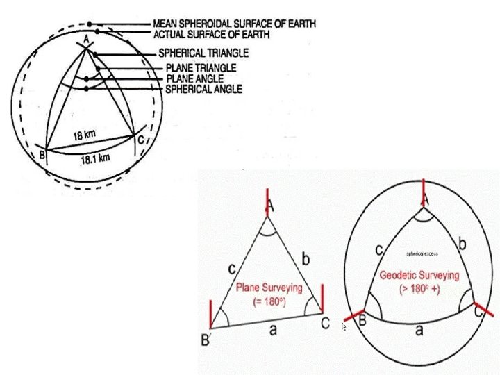

Difference between Plane Surveying & Geodetic Surveying: Plane surveying Geodetic surveying 1. The effect of curvature of earth is not 1. The effect of curvature of earth is considered. 2. The surface of the earth is taken as plane. 2. It involves spherical trigonometry. So it is called trigonometrical survey. 3. The area to be surveyed less than 250 km 2 3. The area to be surveyed more than 250 km 2 4. The degree of accuracy is low. 4. The degree of accuracy is high. 5. Plane surveying is conducted by state agencies 5. Geodetic surveying is conducted by like Survey of India Department. Irrigation department, Railway department. 6.
 Secondary classification 1. Based on Instruments a) Chain surveying, b)")
Classification of Surveying: B) Secondary classification 1. Based on Instruments a) Chain surveying, b) Compass surveying, c) Plane table surveying, d) Theodolite surveying, e) Tacheometric surveying, f) Photographic surveying 2. Based on Methods a) Triangulation surveying, b) Traverse surveying 3. Based on Object: a) Geological surveying, b) Mine surveying, c) Archaeological surveying, d) Military surveying
 Based on nature of field: a) Land surveying, b) Marine")
Classification of Surveying: 4) Based on nature of field: a) Land surveying, b) Marine surveying, c) Astronomical surveying, Land surveying divided into following classes: i) Topographical surveying : - to determine the natural features of country such as rivers, lakes, hills, etc. ii) Cadastral surveying : - to determine the boundaries of fields, estates, houses, etc. iii) City surveying : - to locate the premises, streets, water supply and sanitary system etc. iv) Engineering surveying : - to collect data for designing of engineering works such as roads, reservoirs, railways etc.

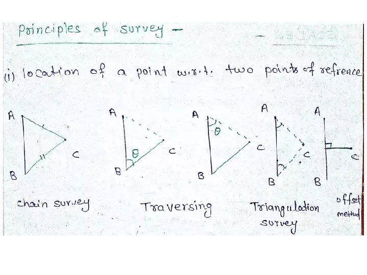
Principles of Surveying: 1. To work from the whole to the part. 2. To locate a new station by at least two measurement ( linear or angular ) from fixed reference points.
 The whole area is")
To work from the whole to the part : 1) The whole area is first enclosed by main stations (controlling stations) and main survey lines (controlling lines). 2) The area is then divided into a number of parts by forming wellconditioned triangles. 3) The main survey lines are measured very accurately with a standard chain and then the sides of triangles are measured.
 The purpose of this process")
To work from the whole to the part: 4) The purpose of this process of working is to prevent accumulation of error. During this procedure, if there is any error in the measurement of any side of a triangle, then it will not affect the whole work. The error can always be detected and eliminated. 5) But, if the reverse process (from the part to the whole) is followed, then the minor error in measurement will be magnified in the process of expansion and these errors will become absolutely uncontrollable.

To locate a new station by at least two measurement ( linear or angular ) from fixed reference points: 1) The new stations should always be fixed by at least two measurement from fixed reference points. 2) Linear measurements refer to horizontal distances measured by chain or tape. 3) Angular measurements refer to the magnetic bearing or horizontal angle taken by a prismatic compass or theodolite.
: 1) It is the ratio of plan distance")
Representative Fraction ( R. F. ): 1) It is the ratio of plan distance to corresponding ground distance. 2) In R. F. both the numerator and denominator should be in the same units. 3) If 10 m on the ground represents 1 cm on the drawing paper, the scale is 1 cm = 10 m. So, R. F. = 1 cm / 10 x 100 cm R. F. = 1/ 1000.

Conventional Symbol:
: EDM instruments are classified based on the type of carrier")
Electronic Distance Measurements (EDM): EDM instruments are classified based on the type of carrier wave as 1) Microwave instruments 2) Infrared wave instruments 3) Light wave instruments.
: The spectrum of an electromagnetic wave is as shown below:")
Electronic Distance Measurements (EDM): The spectrum of an electromagnetic wave is as shown below: Infrared waves and visible light waves are useful for the distance measurement. In EDM instruments these waves are generated, modulated and then propagated. They are reflected at the point up to which distance is to be measured from the instrument station and again received by the instrument. The time taken by the wave to travel this 2 x distance may be measured and knowing the velocity of wave, the distance may be calculated. However time is too short, measuring the time taken is difficult. The improved techniques use phase difference method in which the number of completed wave and incomplete wave is measured. Knowing the length of wave, distances are calculated. Built up microprocessors provided in the instrument calculate the distances and display it by liquid crystal display (LCD). Electronic distance measurement equipment are incorporated along with theodolites that possess automatic angle readout called as total station (electronic tacheometer)
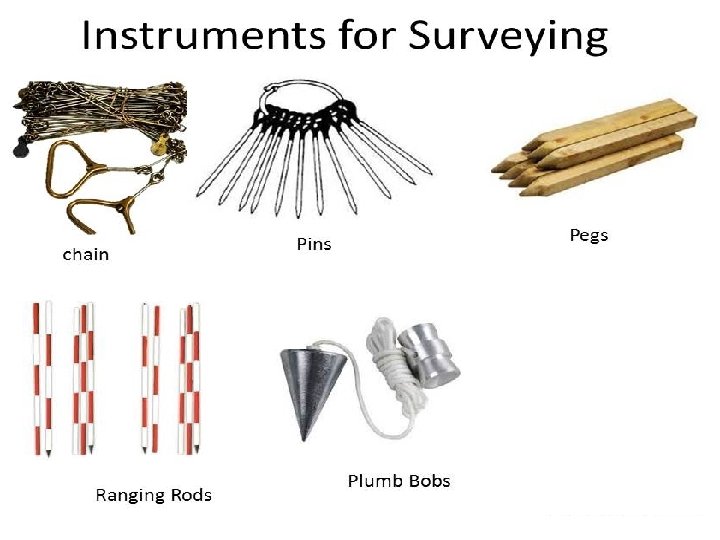
 Ranging Rods. 2) Chains: a) Metric Chain b) Steel")
Accessories For Linear Measurements: 1) Ranging Rods. 2) Chains: a) Metric Chain b) Steel Band c) Engineer’s Chain d) Gunter’s Chain e) Revenue Chain 3) Tapes: 4) Arrows. a) Cloth or Linen Tape b) Metalic Tape c) Steel Tape d) Invar Tape
 Ranging is the process of making a line straight. 2) Rods")
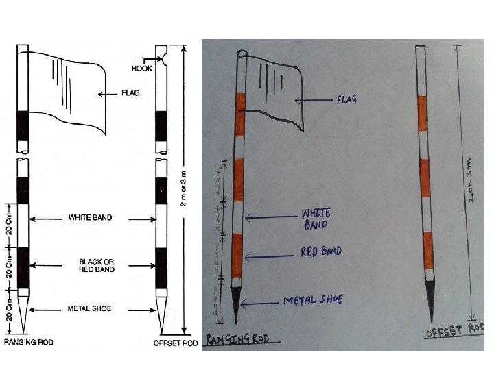
Ranging Rods: 1) Ranging is the process of making a line straight. 2) Rods which are used for ranging a line are known as ranging rods. 3) Rods are made of seasoned timber or seasoned bamboo or GI pipes. 4) Generally circular in section of 25 mm diameter & 2 m or 3 m length. 5) Rod is divided into equal parts of 20 cm each and the divisions are painted black and white or red and white alternately so that the rod is visible from long distance. 6) Lower end of the rod is pointed with iron shoe.
 A chain is prepared with 100 or 150 pieces of galvanized mild")
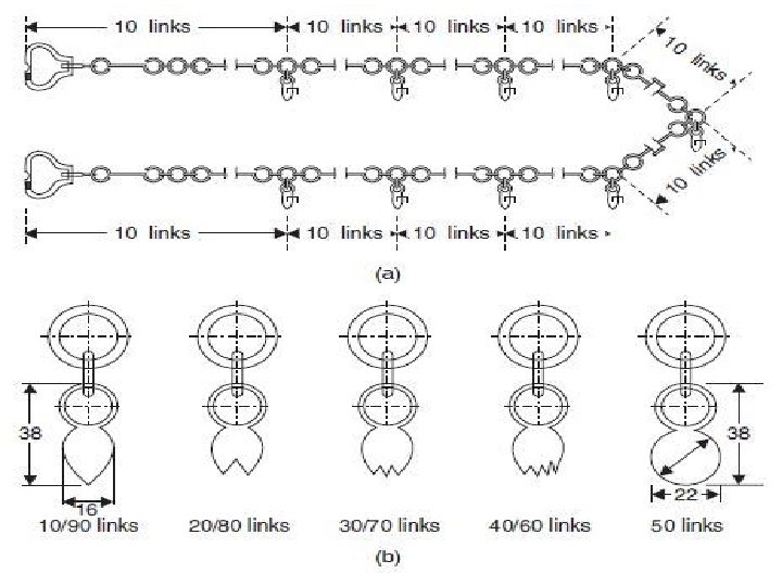
Chains: 1) A chain is prepared with 100 or 150 pieces of galvanized mild steel wire of 4 mm diameter. 2) The ends of the pieces are bent to form lops. 3) Then the pieces are connected together with the help of three oval rings, which make the chain flexible. 4) Two brass handles are provided at the two ends of the chain. 5) Tallies are provided at every 10 or 25 links for facility of counting. 6) One link means the distance between the centers of adjacent middle rings. 7) Types of Chains: a) Metric Chain b) Steel Band c) Engineer’s Chain d) Gunter’s Chain e) Revenue Chain
 Metric Chain b) Steel Band c) Engineer’s Chain d) Gunter’s")
Types of Chains: a) Metric Chain b) Steel Band c) Engineer’s Chain d) Gunter’s Chain e) Revenue Chain
 Available in lengths of 20 m & 30 m. b) 20")
Metric Chain: a) Available in lengths of 20 m & 30 m. b) 20 m chain is divided into 100 links, each of 0. 2 m. Tallies are provided at every 10 links (2 m). Suitable for measuring distance along fairly level ground. Here central tally has circular shape. c) 30 m chain is divided into 150 links, each link is of 0. 2 m. Tallies are provided after every 25 links (5 m). Round brass ring is fixed after every meter. Here central tally has 3 teeth.

30 m chain Tally at 5, 10 , 15, 20 & 25. 1 Link = 0. 2 m No. of links 150
 Steel Band: Ribbon of steel of 16 mm width and 20 or 30")
2) Steel Band: Ribbon of steel of 16 mm width and 20 or 30 m length. Used where more accuracy is required. 3) Engineer’s Chain: 100 ft long & divided into 100 links. Each link is of 1 ft. Tallies are provided at every 10 links. Previously used for all engineering works. 4) Gunter’s Chain: 66 ft long & divided into 100 links. Each link is of 0. 66 ft. Previously used for measuring distance in miles & furlongs. 5) Revenue Chain: 33 ft long & divided into 16 links. Mainly used in cadastral survey.
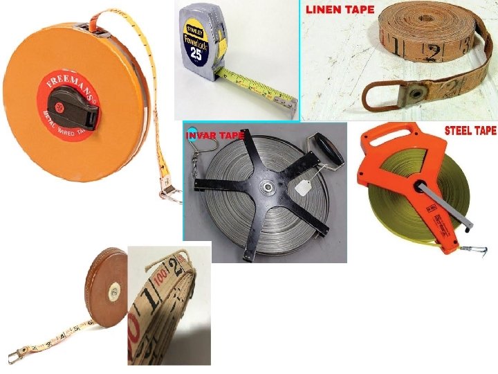
 Cloth or Linen Tape: made up of closely woven linen & is")
Tapes: 1) Cloth or Linen Tape: made up of closely woven linen & is varnished to resist moisture. It is 15 mm wide & available in length of 10 m& 15 m. Generally used for measuring offsets & for ordinary works. 2) Steel Tape: made up of steel ribbon & available in length of 10, 15, 20, 30 & 50 m. It is not used in the fields but used for measurements in constructional works. 3) Invar Tape: made of an alloy 64% & nickel 36%. Thermal coeff. is very low. Ribbon of 6 mm width & length of 30, 50 & 100 m. It is used where maximum precision is required. Generally in triangulation survey conducted by the Survey of India Department. 4) Metallic Tape: when linen tape is reinforced with brass or copper wires to make it durable then it is called a metallic tape. Available in length of 15, 20, & 30 m. It is wound on a leather case with brass handled at the end. Commonly used for all survey works.
 Arrows are made of tempered steel wire of 4 mm diameter. 2)")
Arrows: 1) Arrows are made of tempered steel wire of 4 mm diameter. 2) One end of arrow is bent into a ring of 50 mm diameter & other end is pointed. 3) Overall length is 400 mm. 4) Arrows are used for counting the number of chains while measuring a chain lines.
 The process of establishing points on a straight line between two ends")
Ranging: 1) The process of establishing points on a straight line between two ends points is known as ranging. 2) Ranging must be done before survey line chained. 3) Ranging may be done by direct observation by the naked eye or by line ranger or by theodolite. 4) Generally ranging done by naked eye with the help of three ranging rods. 5) Ranging may be of tow types: 1) Direct 2) Indirect or Reciprocal.
 Direct ranging is possible when the end station are intervisible. When")
Direct Ranging: 1) Direct ranging is possible when the end station are intervisible. When intermediate ranging rods are fixed on a straight line by direct observation from end stations, the process is known as direct ranging. 2) Assume that A & B are two end stations of chain line, where two ranging rods are already fixed. Supposed it is required to fix a ranging rod at the intermediate point P on the chain line in such a way that the points A, P & B are in the same straight line. 3) The surveyor stands about 2 m behind the ranging rod at A by looking towards the line AB. The assistant holds a ranging rod at P vertically at arm’s length. The rod should be held lightly by the thumb & forefinger. 4) Now, the surveyor directs the assistant to move the ranging rod to the left or right until the three ranging rod come exactly in the same straight line. 5) When the surveyor is satisfied that the ranging is perfect, he signals the assistant to fix the ranging rod on the ground by waving both his hand up & down.
 When the end stations are not intervisible due to there being")
Indirect Ranging: 1) When the end stations are not intervisible due to there being high ground between them, intermediate ranging rods are fixed on the line in an indirect way. This method is known, as indirect ranging or reciprocal ranging. 2) Suppose A & B are two end stations which are not intervisible due to high ground existing between them. Suppose it is required to fix intermediate points between A & B. Two chain men take up positions at M 1 & N 1 with ranging rods in their hands.
 The chainman at M 1 stands with his face towards B")
Indirect Ranging: 3) The chainman at M 1 stands with his face towards B so that he can see the ranging rods at N 1 and B. Again, the chainman at N 1 stands with his face towards A so that he can see the ranging rod at M 1 & A. then the chainmen proceed to range the line by directing each other alternately. 4) The chainmen at M 1 directs the chainmen at N 1 to come to the position N 2 so that M 1, N 2 & B are in the same straight line. Again the chainmen at N 2 directs the chainmen at M 1 to move to the position at M 2 so that N 2, M 2 & A are in the same straight line. 5) By directing each other alternately in this manner, they change their position every time until they finally come to the position M & N which is straight line AB.
 To open a chain, the strap is unfastened and the")
Unfolding of Chain: 1) To open a chain, the strap is unfastened and the two brass handles are held in the left hand the bunch is thrown forward with the right hand. 2) Then one chainmen stands at the starting station by holding one handle and another moves forward by holding the other handle until the chain is completely extended. Folding of Chain: 1) A chainmen should move forward by pulling the chain at the middle. Then two halves of the chain will come side by side. 2) Start from the center of chain, two pairs of links are taken at a time with the right hand & placed on the left hand alternately in both directions. 3) Finally, two brass handles will appear at the top. Bunch should be then fastened by the strap.
 The chainmen at the forward end of the chain, who drags the")
Leader: 1) The chainmen at the forward end of the chain, who drags the chain forward, is known as the leader. 2) Leader will fix the arrow on the ground at the end of chain & obey the instruction of follower. Follower: 1) The chainmen at the rear end of the chain, who holds the zero end of the chain at the station, is known as the follower. 2) Follower will direct the leader at the time of ranging & also pick up the arrows inserted by the leader.
 When a magnetic needle is suspended freely, it will show a")
Magnetic Bearing: 1) When a magnetic needle is suspended freely, it will show a direction which is known as the magnetic meridian. 2) The angles that a line makes with the magnetic meridian is known as the magnetic bearing of the line. 3) Magnetic bearing is expressed as I. Whole Circle Bearing and II. Reduced or Quadrantal Bearing
 : 1) The magnetic bearing of a line is measured")
Whole Circle Bearing (WCB) : 1) The magnetic bearing of a line is measured clockwise from the north pole towards the line is known as the Whole Circle Bearing. 2) WCB may have any value between 00 & 3600 3) WCB of a line is obtained by Prismatic Compass.
 : 1) The magnetic bearing of a line measuring clockwise or")
Quadrantal Bearing (QB) : 1) The magnetic bearing of a line measuring clockwise or counterclockwise from the North Pole or South Pole ( whichever is nearer the line) towards the East or West. 2) This system consists of four quadrants – NE, SW & NW. 3) The values of QB may lie between 00 to 900. 4) QB is obtained by Surveyor Compass.
 : 1) When the Whole Circle Bearing of a line is")
Reduced Bearing (QB) : 1) When the Whole Circle Bearing of a line is converted to Quadrantal Bearing, it is termed as Reduced Bearing. 2) RB is similar to QB. 3) The bearing is measured clockwise or counterclockwise from the north or south towards the east or west.
 The principle of chain surveying is triangulation. 2)")
Principle of Chain Surveying : 1) The principle of chain surveying is triangulation. 2) Triangulation means the area to be divided into a number of small triangles which should be conditioned. 3) In chain surveying, the sides of the triangles are measured directly on the fields by chain or tape and no angular measurements are taken. 4) Tie line & check lines control the accuracy of work. 5) Chain surveying is suitable when ground surface is more or less level, small area, formation of well-conditioned triangles.

Reconnaissance Survey: Primary investigation of the area before start of any survey work. Survey Stations: Points at the beginning and the end of a chain line. They may also occur at any convenient points on the chain line. Main Stations: Stations taken along the boundary of an area as controlling points are known as main stations. Main Survey Lines: The lines joining the main stations are called main survey lines. Main survey lines should cover the whole area to be surveyed. Subsidiary Stations: Stations which are on the main survey lines or any other survey lines are known as subsidiary station. These stations are taken to run subsidiary lines for dividing the area into triangles for checking the accuracy of triangles and for locating interior details. Base Line: The longest of the main survey line is considered as base line & which is most important line. It should be measured very carefully & accurately. Offset: The lateral measurements taken from an object to the chain line is known as offset. Perpendicular & Oblique.
 When area is large, undulating & crowded with many details")
Compass Traversing : 1) When area is large, undulating & crowded with many details then triangulation is not possible. In such a area method of traversing is adopted. 2) In traversing, a framework consists of a number of connected lines. 3) The length are measured by tapes or chains & direction by angle measuring instruments. 4) Angle measuring instruments used is compass & process is known as compass traversing.

True Meridian: The line passing through geographical north pole, geographical south pole and any point on the surface of the earth. True Bearing: The angle between the true meridian & a line is known as True Bearing of the line. Magnetic Meridian: When a magnetic needle is suspended freely and balanced properly, unaffected by magnetic substance, it indicates a direction. This direction is known as the magnetic meridian. Magnetic Bearing: the angle between the magnetic meridian & a line is known as the magnetic bearing or simply the bearing of the line.
 Every line has two bearings: one is observed")
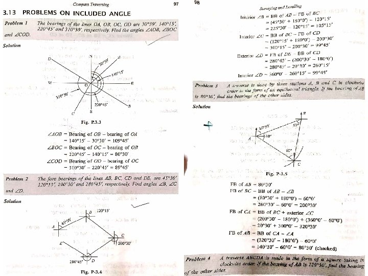
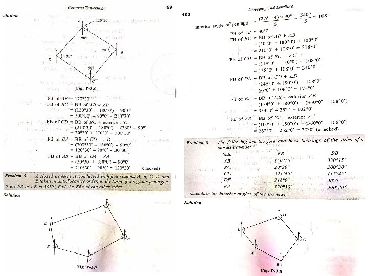
Fore Bearing & Back Bearing: 1) Every line has two bearings: one is observed along the progress of the survey or forward direction, and is called Fore Bearing and the second one is observed in the revers or opposite direction and is called Back Bearing. 2) Fore Bearing & Back Bearing of a line differ exactly by 1800. 3) Back Bearing = Fore Bearing + 180 4) Use +ve sign when fore bearing is less than 180 & use –ve sign when it is more than 180. 5) In case of quadrantal bearing system, The numerical value of FB & BB is equal but the quadrants are just opposite. FB is N 300 E then its BB is S 300 W

Magnetic Declination: Ø The horizontal angle between the magnetic meridian & true meridian is known as Magnetic Declination. Dip of Magnetic Needle: Ø The needle is found to be inclined towards the pole. This inclination of the needle with the horizontal is known as the dip of the magnetic needle.
 A magnetic needle indicates the north direction when freely suspended or")
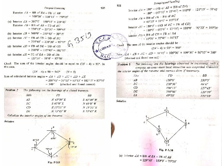
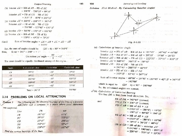
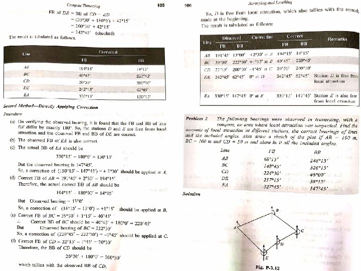
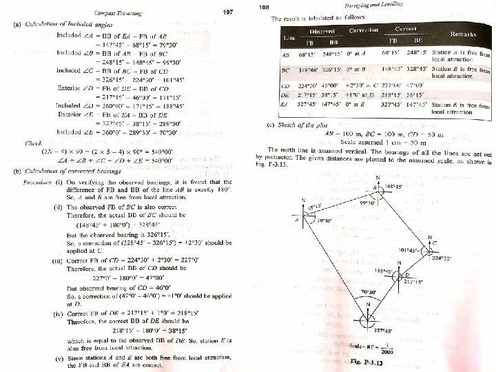
Local Attraction: 1) A magnetic needle indicates the north direction when freely suspended or pivoted. 2) But if the needle comes near some magnetic substances, such as iron ore, steel structure, electric cables conveying current, etc. it is found to be deflected from its true direction, & does not show the actual north. This disturbing influence of magnetic substances is known as local attraction. 3) To detect the presence of local attraction, the fore & back bearing of a line should be taken. If the difference of FB & BB of the line is exactly 1800 then there is no local attraction. 4) To compensate for the effect of local attraction, the amount of error is found out and is equally distributed between the FB &BB of the line. Observed FB of AB = 60030’ & Observed BB of AB = 240000’ Calculated BB of AB = 60030’ + 180000’ = 240030’ Corrected BB of AB = (1/2) * (240000’ + 240030’ ) Corrected FB of AB = 240015’ - 180000’ = = 240015’ 60015’
 The principle of compass surveying is traversing, which involves")
Principle of Compass Surveying: 1) The principle of compass surveying is traversing, which involves a series of a connected lines. 2) The magnetic bearings of lines are measured by prismatic compass & distance of the lines are measured by chain. 3) Interior details are located by taking offsets from the main survey lines. Sometimes subsidiary lines may be taken for locating these details. 4) Compass surveying is recommended when area is large, area is crowded with many details & triangulation is not possible & the course of river or coast line is to be surveyed. 5) Compass surveying is not recommended for area where local attraction is suspected.
 Surveying which involves a series of connected line is known as traversing.")
Traversing: 1) Surveying which involves a series of connected line is known as traversing. 2) The sides of the travers are known as traverse legs. 3) Traverse are of two types: Closed Traverse & Open Traverse. Closed Traverse: when a series of a connected lines forms a closed circuit, i. e. when the finishing point coincides with the starting point of a survey, it is called a closed traverse. Open Traverse: When a sequence of connected lines extends along a general direction and does not return to the starting point, it is known as open traverse or unclosed traverse.
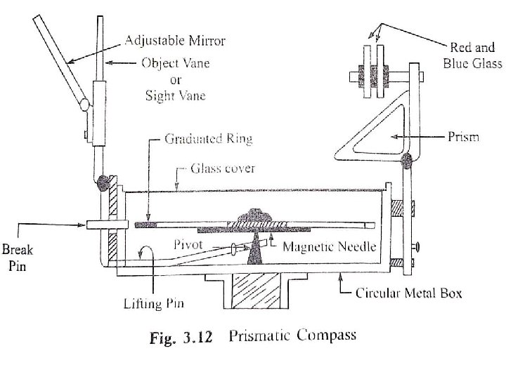
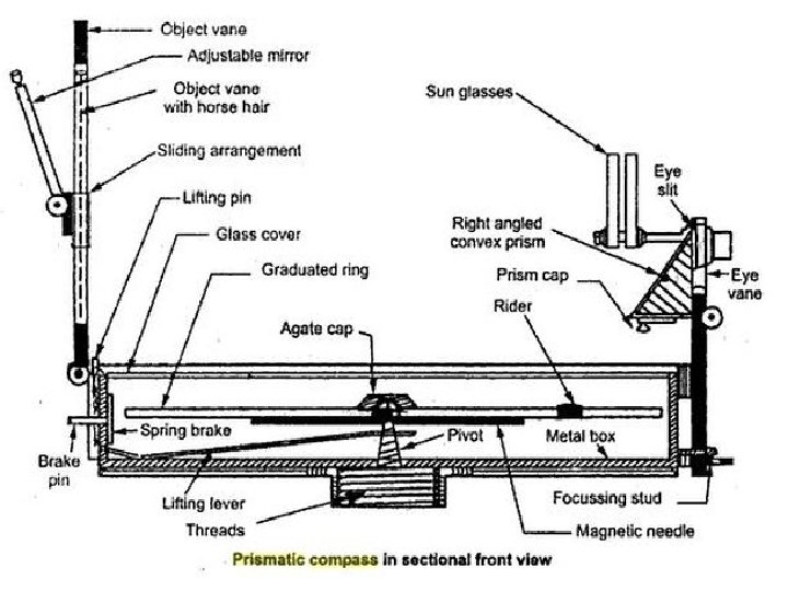
 Prismatic Compass 2) Surveyor Compass Prismatic Compass: The readings are")
Types of Compasses: 1) Prismatic Compass 2) Surveyor Compass Prismatic Compass: The readings are taken with the help of a prism. The essential parts of compass are as below: 1) Compass Box 2) Magnetic Needle & Graduated Ring 3) Sight Vane & Prism 4) Dark Glasses 5) Adjustable Mirror 6) Brake Pin 7) Lifting Pin 8) Glass Cover

Prismatic Compass: The readings are taken with the help of a prism. The essential parts of compass are as below: 1) Compass Box: Circular non magnetic metal box 8 to 10 cm diameter with pivot at center. 2) Magnetic Needle & Graduated Ring: Magnetic needle is attached to graduated aluminum ring. 0 to 360 & 0 marked at North. Least count is 30 minutes. 3) Sight Vane & Prism: They are fixed diametrically opposite to the box. 4) Dark Glasses: Red Glass for sighting luminous object at night & Blue Glass in bright daylight to reduce strain on eyes. 5) Adjustable Mirror: Provided with sight vane to observe the object when it is too low or high w. r. t. line of sight. 6) Brake Pin: At the base of sight vane to stop the oscillation of ring. 7) Lifting Pin: Below the sight vane, when eye sight folded it presses pin to avoid damages to magnetic needle. 8) Glass Cover: On top of box to protect aluminum ring from dust.
 There is no prism on it. Readings are taken with the")
Surveyor Compass: 1) There is no prism on it. Readings are taken with the naked eyes. 2) It consists of an eye vane in place of prism with a fine sight slit. 3) The graduated aluminum ring is attached to the circular box. It is not fixed to the magnetic needle. 4) The magnetic needle moves freely over the pivot. The needle shows the reading on the graduated ring. 5) The ring is graduated from 00 to 900 in 4 quadrants. 6) No mirror is attached to the object vane.
 Fixing of Compass with Tripod Stand. 2) Centering.")
Temporary Adjustment of Prismatic Compass: 1) Fixing of Compass with Tripod Stand. 2) Centering. 3) Leveling. 4) Adjustment of Prism. 5) Observation of Bearing.
 Instrumental Error. 2) Personal Error 3) Other")
Sources of Error in a Compass: 1) Instrumental Error. 2) Personal Error 3) Other Sources of Error.
 Centering should be done perfectly. 2)")
Precautions to be taken in Compass Surveying: 1) Centering should be done perfectly. 2) To stop the rotation of the ring, the brake pin should be pressed very gently and not suddenly. 3) Readings should be taken along the line of sight and not from any side. 4) The stations should not be selected near the magnetic substances. 5) The observer should not carry magnetic substance.
 Explain adjustment of closing error in closed traverse? 2) Explain sources")
Assignment-I : 1) Explain adjustment of closing error in closed traverse? 2) Explain sources of error in a compass? 3) Explain obstacle in chaining? 4) Write a short note on tape & chain corrections also explain with few numerical solutions?
- Slides: 73