
Survey of ShortReach Optical Interconnect Ken Pedrotti Robert
Survey of Short-Reach Optical Interconnect Ken Pedrotti Robert Dahlgren Presented 10 November 2005
Outline • • Introduction Pure silica fiber trends Splicing trends Connector trends Active component trends Transceiver module trends What to expect in the year 2010? Questions and discussion
Short Reach Links < 300 m • Optical Internetworking Forum (OIF) – VSR-1 through VSR-4 classifications • Gigabit Ethernet – Multimode 850 nm • 10 Gigabit Ethernet – Singlemode or parallel multimode • Fibre Channel • Serial HIPPI • Proprietary links
Main Commercial Trends • Fiber to the home/curb/pedestal deployment is moving forward • Common form factors • Smaller form factors • Standards-based specifications • “Short Reach” and VSR standards • Convergence of specs at 1 and 10 Gbps • WDM begat DWDM and CWDM • Pure silica core fiber less of a niche • Ribbon fiber and mass splicing/termination
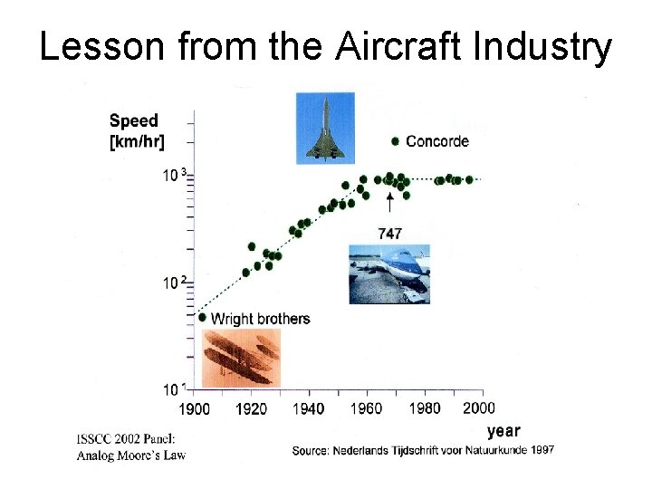
Lesson from the Aircraft Industry
Convergence • Telecom and datacom PHYs have less distinction • Traditional datacom companies like Cisco are making more carrier-class equipment • Common medium (often SMF) • Data rates moving towards convergence – OC-192, 10 G Ethernet, 10 G Fibre Channel • Possible to unify component markets to take advantage of economies of scale
What Convergence Means for VSR Links • 1 and 10 Gbps may be the “sweet spot” for short links up to 300 m for some time – 850 nm VCSEL and MMF – Single and multi-fiber arrangements • Broad support from industry in volume • Common electrical interface • 40 Gbps and 100 Gbps serial technology too expensive for VSR • WDM approaches not suitable for VSR
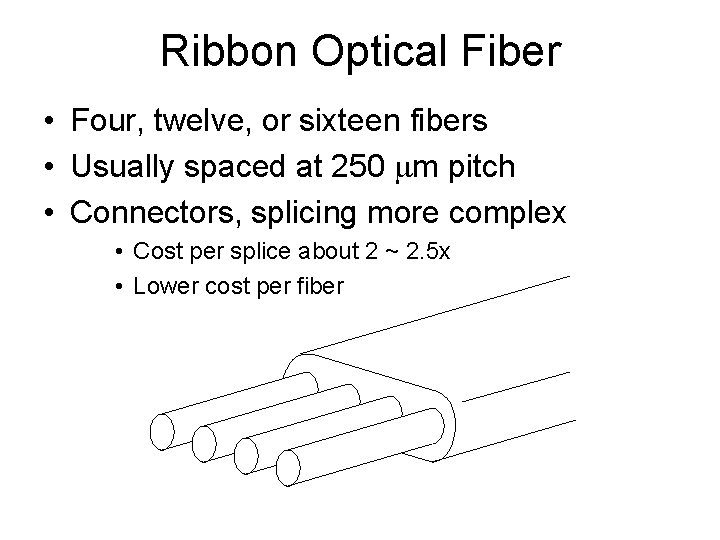
Ribbon Optical Fiber • Four, twelve, or sixteen fibers • Usually spaced at 250 mm pitch • Connectors, splicing more complex • Cost per splice about 2 ~ 2. 5 x • Lower cost per fiber
Pure-Silica Core Fiber Trends • Several manufacturers now make optical fiber for high radiation environments. • Singlemode, step-index multimode, graded index multimode • Cost premium ~TBD compared to standard (e. g. Ge-doped core) fiber of the same type • Improved polymer coatings
Pure-Silica Core Fiber Vendors • • • Fujikura Ltd. Oxford Electronics Mitsubishi International Verrillion Inc. OFS (formerly Lucent) Cor. Active – On custom basis Sumitomo Electric 3 M dropped production Corning – MMF in development
Evolution of Arc Fusion Splicing • Active alignment with optical source and detector at the fiber endfaces • Local injection into core and detection • Imaging-based alignment • Ribbon fiber splicers (mass splicing) • V-groove (passive) splicers • Enabled by tighter fiber concentricity specs • Smaller, lighter, better ergonomics • Compensation schemes, loss estimation
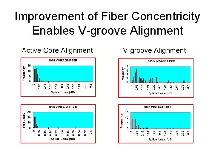
Improvement of Fiber Concentricity Enables V-groove Alignment Active Core Alignment V-groove Alignment
Splicing trends • Continued acceptance of v-groove based splicers in non R&D applications • Continuing acceptance of mass fusion splicing for ribbon fiber • Continued development of custom splice programming, e. g. thermal diffusion core expansion for specialty fiber • Laser-based fiber stripping and cleaving needs cost reduction
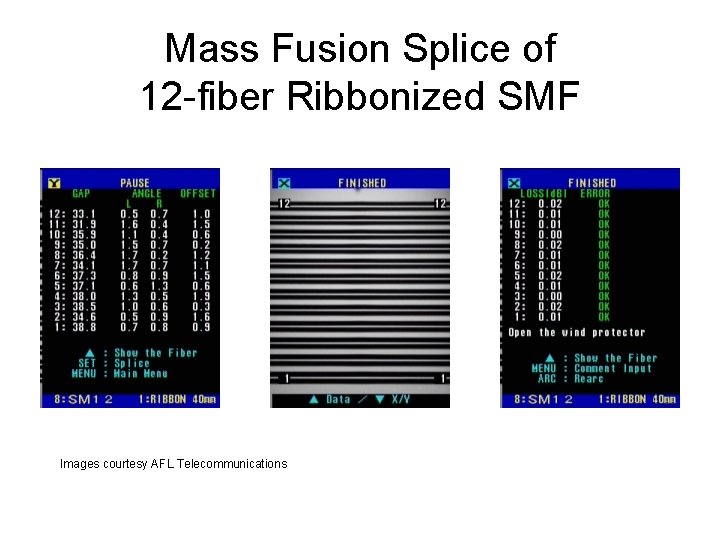
Mass Fusion Splice of 12 -fiber Ribbonized SMF Images courtesy AFL Telecommunications
Splice Economics • Splicing cost roughly 20~40 € not including costs associated with access and packaging. Can be much higher. • Mass splices cost roughly 2 ~ 2. 5 x for a 12 fiber ribbon • Spliceless ATLAS design tradeoff • Need lower cost fiber recoating systems and proof-testers for High-Rel applications • Splicer manufacturers: Fitel, Fujikura, 3 sae
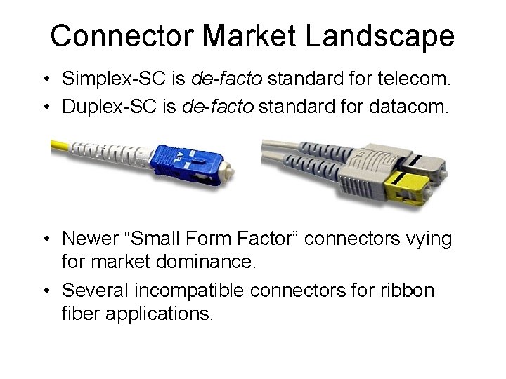
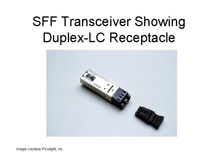
Connector Market Landscape • Simplex-SC is de-facto standard for telecom. • Duplex-SC is de-facto standard for datacom. • Newer “Small Form Factor” connectors vying for market dominance. • Several incompatible connectors for ribbon fiber applications.
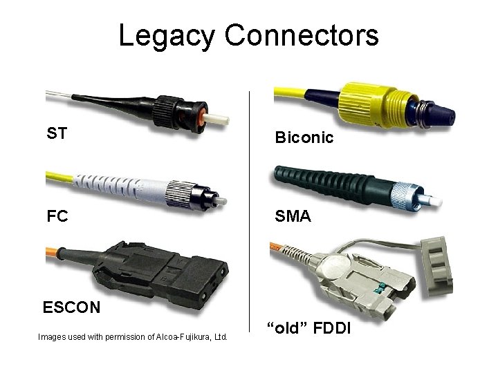
Legacy Connectors ST Biconic FC SMA ESCON Images used with permission of Alcoa-Fujikura, Ltd. “old” FDDI
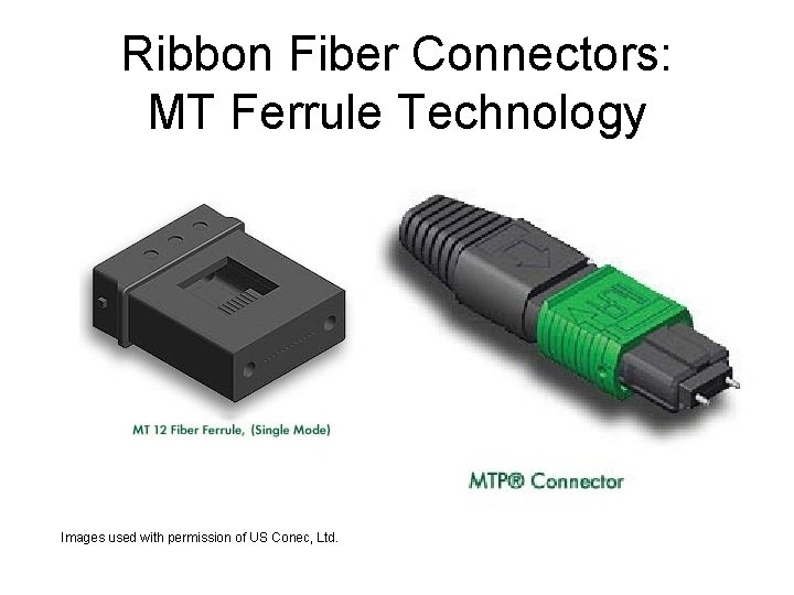
Ribbon Fiber Connectors: MT Ferrule Technology Images used with permission of US Conec, Ltd.
Small Form Factor Connectors • Driven by smaller front-panel opening, like the ubiquitous R-45 telephone/ethernet jack. • Driven by low-cost 100 Mbps and 1 Gbps ethernet system and cable companies – High front panel density = low cost/port • Telcos are looking to replace SC connector – High front panel density = CO and closet space • Incorporate cost-saving features • Incorporate ergonomic features • Some allow field termination
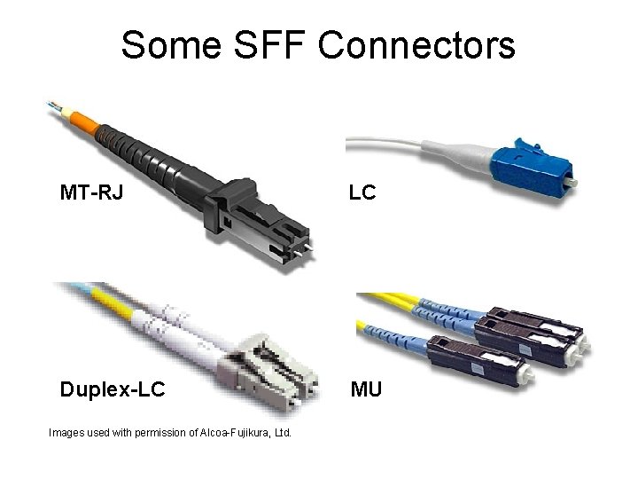
Some SFF Connectors MT-RJ LC Duplex-LC MU Images used with permission of Alcoa-Fujikura, Ltd.
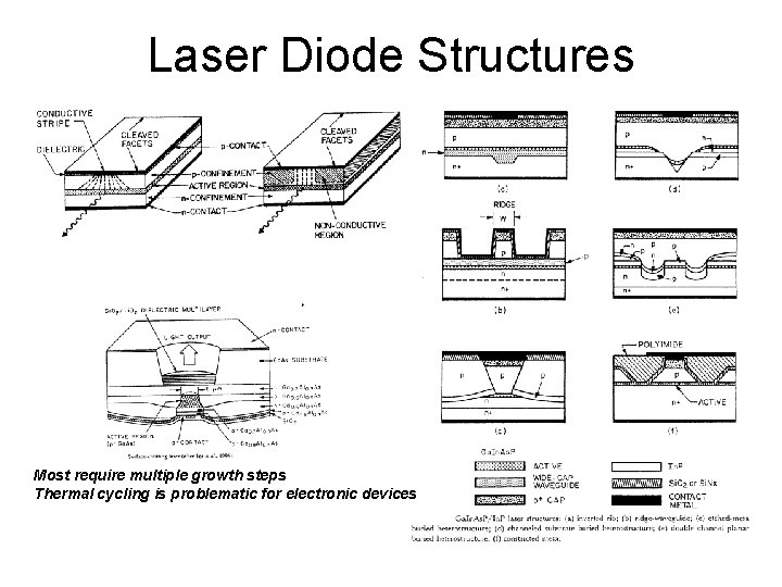
Laser Diode Structures Most require multiple growth steps Thermal cycling is problematic for electronic devices
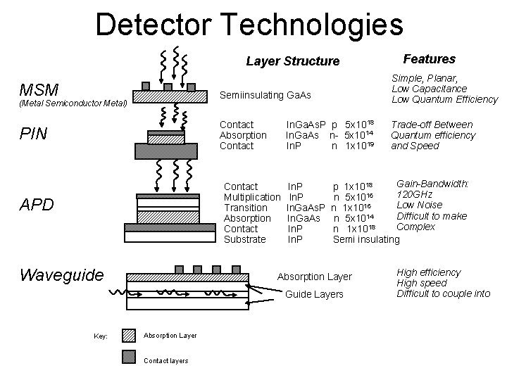
Detector Technologies Layer Structure MSM (Metal Semiconductor Metal) PIN Semiinsulating Ga. As Simple, Planar, Low Capacitance Low Quantum Efficiency Contact Absorption Contact Trade-off Between Quantum efficiency and Speed In. Ga. As. P p 5 x 10¹⁸ In. Ga. As n- 5 x 10¹⁴ In. P n 1 x 10¹⁹ Contact Multiplication Transition Absorption Contact Substrate APD Waveguide In. P In. Ga. As In. P Gain-Bandwidth: p 1 x 10¹⁸ 120 GHz n 5 x 10¹⁶ 16 Low Noise n 1 x 10 14 Difficult to make n 5 x 10 Complex n 1 x 10¹⁸ Semi insulating Absorption Layer Guide Layers Key: Absorption Layer Contact layers Features High efficiency High speed Difficult to couple into
VCSEL status and trends • VCSELs dominate where DFB laser or high power is not needed • Many suppliers at the 1 Gbps level • Reliability established at 850 nm • 1300 nm devices have been slow to reach commercialization • Low cost visible VCSELs becoming available at 635 and 650 nm • TBD 3 Gbps and 10 Gbps
Semiconductor Trends • CMOS and Si. Ge-Bi. CMOS has taken over the chip market up to 10 Gb/s rates • 40 Gb/s OC-768 is waiting, with components ready but deployments few • As long haul market has softened component manufacturers have targeted current new developments at gigabit and 10 G Ethernet applications • Addition of Forward error correction (FEC) drives maximum bit rate up eg. SONET 9. 952 Gb/s to 12. 5 Gb/s with a 5 -6. 5 coding gain • Chips appearing designed for RZ rather than NRZ applications
Semiconductor Trends • Transceivers are including more monitoring and feedback control elements in chips to reduce part counts and size • With CMOS implementations practical at 10 Gb/s more multirate-multiprotocol solutions appearing thus increasing volumes and lowering product costs • More network protocol processing in highly integrated chips • Transmitters with low speed supervisory tone modulation inputs • Equalization and compensation of analog links • Smaller packaging • TBD rad-hard electronics
Transceivers conform to standards • • Under the auspices of IEEE, ANSI, ITU… Highly technical, dry, and can be political. Strict rules of operation, balloting to approve. Communication protocol and Physical Layer – SONET, Fibre Channel, ATM, Gigabit Ethernet… • Optical connector intermatability standard – Duplex-SC, duplex-LC, MT-RJ, SG… • Environmental – Telecordia, Product Safety, Military, EMC…
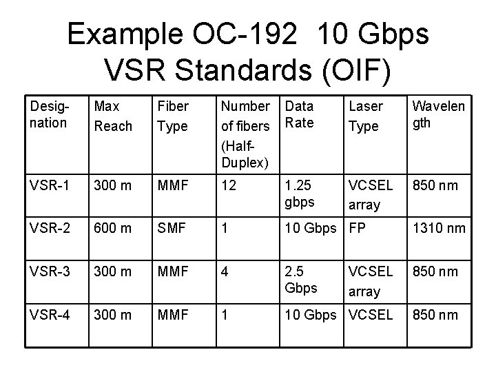
Example OC-192 10 Gbps VSR Standards (OIF) Designation Max Reach Fiber Type Number of fibers (Half. Duplex) Data Rate Laser Type Wavelen gth VSR-1 300 m MMF 12 1. 25 gbps VCSEL array 850 nm VSR-2 600 m SMF 1 10 Gbps FP 1310 nm VSR-3 300 m MMF 4 2. 5 Gbps VCSEL array 850 nm VSR-4 300 m MMF 1 10 Gbps VCSEL 850 nm
Transceivers conform to MSAs • Standards bodies only define the minimum necessary requirements for interoperability. • Multi-source Agreements (MSAs) between manufacturers describe common features outside of the standard, e. g. module pinout • Generates consensus and critical mass without violating anti-trust guidelines. • Electrical connector/formfactor standards – 1 x 9, GBIC, GLM, 2 x 5, 2 x 10, SFP… – 200 pin, 300 pin, XFP, Xenpak…
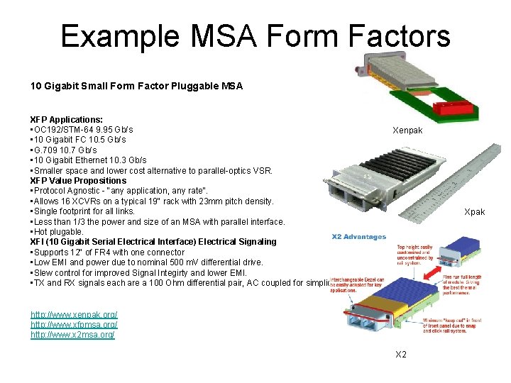
Example MSA Form Factors 10 Gigabit Small Form Factor Pluggable MSA XFP Applications: • OC 192/STM-64 9. 95 Gb/s • 10 Gigabit FC 10. 5 Gb/s • G. 709 10. 7 Gb/s • 10 Gigabit Ethernet 10. 3 Gb/s • Smaller space and lower cost alternative to parallel-optics VSR. XFP Value Propositions • Protocol Agnostic - "any application, any rate". • Allows 16 XCVRs on a typical 19" rack with 23 mm pitch density. • Single footprint for all links. • Less than 1/3 the power and size of an MSA with parallel interface. • Hot plugable. XFI (10 Gigabit Serial Electrical Interface) Electrical Signaling • Supports 12" of FR 4 with one connector • Low EMI and power due to nominal 500 m. V differential drive. • Slew control for improved Signal Integirty and lower EMI. • TX and RX signals each are a 100 Ohm differential pair, AC coupled for simplicity. Xenpak Xpak http: //www. xenpak. org/ http: //www. xfpmsa. org/ http: //www. x 2 msa. org/ X 2
SFF Transceiver Showing Duplex-LC Receptacle Image courtesy Picolight, Inc.
XAUI Electrical Interface • • Defined in IEEE 802. 3 ae, section 42 Extends the Media Independent Interface Fewer pins than full parallel I/O Quartet of differential pair per direction 3. 125 Gbps per lane XAUI chips resets jitter accumulation XAUI chips establish lane order XAUI chips eliminates lane-to-lane skew
Transceiver Trends • More intelligence and RAM in modules • Price erosion of 10 Gbps modules • Garden variety 1 Gbps modules at nearcommodity pricing • Equalization of optical dispersion • Vcc of 3. 3 V (and lower) rather than 5 V • Better EMI and ESD margins • Gbps modules for polymer optical fiber • Special Bi. Di modules for FTTx
What to expect in 2010 for VSR Data Links • • Fiber used in shorter and shorter links 1300 nm VCSELs Silicon Photonics Resonant microcavity devices Few new connectors Electronic dispersion compensation More intelligence in transceivers Inexpensive mini fusion splicers
Questions • Is one gigabit/second technology adequate for the lifetime of the detector? • Radiation hardness of VCSELs and commercially-available transceivers • Can we use 1310/850 Bi. Di module to aid with photobleaching? • Is it economically feasible for spliceless design made completely of pure silica fiber • Suitability of photonic crystal fiber
- Slides: 34