Surveillance Bot Group 9 Charlie Grubbs Daniel Lanzone

Surveillance Bot Group 9 Charlie Grubbs Daniel Lanzone Mike Roosa Ryan Tochtermann

Overview Goals Motivation �To create a scalable �Robotics all-terrain remote surveillance system with stabilization platform �Audio detection capable of monitoring stereo sound levels �Real-time video link �Intuitive user-interface �Systems Integration �Scalability

Objectives �Vehicle can operate at a minimum of 4 MPH for at least 30 minutes �Camera stabilization platform capable of correction at a rate of 50 Hz �Pitch and roll correction of 45 deg. and a minimum of 60 deg/s correction rate �Stereo audio detection up to 10 k. Hz �Wireless communication of at least 100 yards outdoors

 �Capable of")
Vehicle Chassis Overview �Capable of moving over semi-rugged terrain (unlevel, rocky, grassy) �Capable of overcoming ramped obstacles (< 35˚) �Moderate suspension for Z-axis stabilization � 4 mph �Low profile for stability

Vehicle Chassis : Suspension �Two passive shock absorbers on each front wheel �One passive shock absorber for rear axis

Vehicle Chassis: Motors Steering Motor Drive Motor � 50 RPM � 2500 RPM No Load � 12 VDC rating �High torque gear �Direct drive box �Built-in potentiometer for position sensing

Vehicle Chassis: Motor Controller �Two bidirectional motor ports �Driver: L 298 Dual HBridge IC �Control: 3 digital pins per motor: 1 for enable, and 2 for motor direction � 6 - 35 VDC Regulation �Up to 2 A Output

Stabilization Platform

Stabilization Requirements �Pitch and Roll Correction rate of 50 Hz � 10 W peak power consumption (pitch and roll servos)
 �Sensitivity ± 250, ± 500, ± 1000, and ± 2000")
Inertial Measurement Unit (IMU) �Sensitivity ± 250, ± 500, ± 1000, and ± 2000 dps �Small form-factor (4 x 4 x 0. 9 mm QFN) �Low power consumption �Low drift Part Number Axes Type Size Price ITG-3200 3 Gyroscope Small $24. 95 ITG-3200 BO 3 Gyroscope Large $49. 95 MPU-6050 3 Accelerometer/ Gyroscope Large $39. 95 9 DOF Razor 3 Large $124. 95 IDG 1215 2 Accelerometer/ Gyroscope/ Magnetometer Gyroscope Small $24. 50

Stabilization �Uses accelerometer and gyroscope �Kalman filter �Accelerometer data is good for long time periods �Gyroscope is good for short time periods


Microcontroller Decision Model ATmega 2560 Input I/O Voltage Pins 1. 8 -5. 5 V 86 ATmega 16 U 2 2. 7 -5. 5 V 22 ATmega 328 1. 8 -5. 5 V 23 Frequency CPU Flash 16 MHz (Max) 8 -bits 256 KB 16 MHZ (Max) 20 MHZ (Max) 8 -bits 16 KB 8 -bits 32 KB
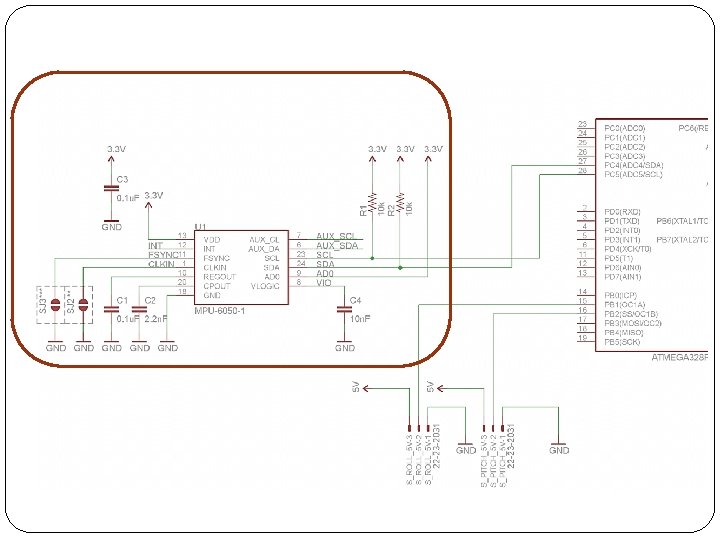

Stabilization Software �ATmega 328 – C/C++ libraries �Microcontroller will be used to implement software �Reading of IMU sensor via I 2 C bus �Kalman filter �Controlling servos


Hitec HS-5485 Servo motors �Controls: �Pitch �Roll � 3. 3 V to 6 V � 60 deg in. 18 seconds (no load) �Mass: 59. 82 g �Dimensions: 40. 39 mm x 19. 56 mm x 37. 59 mm � 180 degree resolution

Wireless camera Camera requirements Cisco-Linksys Wireless. N � 320 x 240 resolution � 640 x 480 max �IP camera resolution �MJPEG stream �Microphone � 30 FPS � 5 V Barrel-jack input � 15 FPS

Camera Testing �Camera tested at a peak bandwidth 1. 2 Mbps with highest image quality setting and 30 FPS �Configured as an Ad-hoc network, the latency was reduced significantly

Audio Detection System

Overview �Detects close-range audible events that occur outside the camera’s field of view �Audio detection from 70 Hz – 12, 000 Hz �Stereo detection �Two microphones mounted to chassis, facing east and west �One stage signal amplification chain �DSP on ATmega 328 �Wireless communication via Xbee �User alerted via the GUI

Microphone Specs �Audio Technica dynamic instrument microphone �Generates peak of ~5 m. V �Modifications

Analog Onboard Audio Signal Processing �Microphone connection to PCB �Amplifier LM 386 �One gain stage �Gain of 50

Output to microcontroller

GUI �Visual Design
 Voltage Output (m.")
SPL Input / Output Voltage Correspondence SPL Input (d. B ) Voltage Output (m. V) Gain Adjusted Voltage Output (V) 0 ~0 2. 27 10 ~0 2. 27 20 ~0 2. 27 30 ~0 2. 27 40 0. 14 2. 29 50 0. 86 2. 32 60 1. 96 2. 38 70 4. 65 (Max Sensitivity) 2. 51 80 4. 65 2. 51
")
SPL Input / Output Voltage Correspondence 2. 55 2. 5 Gain Adj. Voltage (V) 2. 45 2. 4 2. 35 2. 3 2. 25 2. 2 2. 15 2. 1 0 10 20 30 40 50 SPL Input (d. B) 60 70 80

Sound Level / Notification Correspondence 0 V to 0. 353 V 2. 55 2. 5 Gain Adj. Voltage (V) 2. 45 2. 4 Level 0 2. 35 2. 3 2. 25 2. 2 2. 15 2. 1 0 10 20 30 40 50 SPL Input (d. B) 60 70 80

Sound Level / Notification Correspondence 0. 353 V to 1. 061 V 2. 55 Gain Adj. Voltage (V) Level 1 2. 5 2. 4 2. 35 2. 3 2. 25 2. 2 2. 15 2. 1 0 10 20 30 40 50 SPL Input (d. B) 60 70 80

Sound Level / Notification Correspondence 1. 061 V to 3. 535 V 2. 55 Gain Adj. Voltage (V) Level 2 2. 5 2. 4 2. 35 2. 3 2. 25 2. 2 2. 15 2. 1 0 10 20 30 40 50 SPL Input (d. B) 60 70 80
")
Sound Level / Notification Correspondence 3. 353 V 2. 55 Gain Adj. Voltage (V) Level 3 2. 5 2. 4 2. 35 2. 3 2. 25 2. 2 2. 15 2. 1 0 10 20 30 40 50 SPL Input (d. B) 60 70 80
 �Maps input voltages from 0 V to 5 V �Will")
Microcontroller Interfacing �analog. Read() �Maps input voltages from 0 V to 5 V �Will use full resolution of 4. 8 m. V (10 bit) �Software/Programming �Loop that constantly checks input voltage from microphone �Changes output based on notification level

Communication Systems

Communications System Overview �Capable of reliable and accurate data transmission �Relatively long range (100+ yards) �Low power consumption �Relatively simple setup and configuration

Communications System Overview �The goal is to create a network between the PC and the vehicle in order to send control and sensor data between them. �It will feature a PC-side and embedded-side system, each consisting of a wireless RF module and a regulated serial interface between the module and the PC or onboard microcontroller.

XBee Series 2 RF Modules Key Features: � 3. 3 V @ 40 m. A operation �Data rates up to 250 kb/s � 400 ft (133. 33 yd) range Pros: �Long range �Low power consumption �Low cost Cons: �For Series 2 modules; difficult to configure for point-to-point communication Xbee Series 2 Module – 2 m. W Antenna Model

Embedded-Side Interfacing �Because the XBee operates at 3. 3 V and the At. Mega 328 operates at 5 V, a voltage regulator is required for VCC input. �A level-shifting diode is also required on the Xbee’s Data In line to account for this voltage difference. �Other pins are connected to the microcontroller

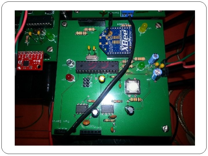
Embedded-Side Development �The Arduino XBee Shield is a simple interface between wireless module and microcontroller �Takes care of all voltage regulation, I/O connections, and status LEDs �Still allows access to all other Arduino pins Development/Testing using Arduino’s XBee Shield

PC-Side Interfacing �An XBee Explorer USB will be used to connect the other XBee module to the PC. �The device uses an FT 232 RL USB to RS 232 serial UART to interface between the XBee and the PC. �Takes care of voltage regulation and I/O connections for easy development and RS-232 to USB connection via XBee Explorer

Successes and Difficulties Successes: Difficulties: 1. Established a reliable � Getting the Series 2 wireless network. 2. Sent and received messages between microcontroller and PC 3. Wireless drive control of surveillance vehicle for over 100 yards. 4. Sensor data acquired for over 100 yards. XBee modules to talk quickly and reliably. Solution: Module is configured to broadcast mode for mesh networks by default. Must be changed to have only one destination node every time it is powered up.

Control Software Overview �PC-Side Software �Embedded-Side �Simple GUI for Software complete control �Must receive user and current status control data and of surveillance respond vehicle accordingly �Must receive �Must relay sensor data and data to PC-side display it in a software simple format �Must transmit user control data quickly

PC-Side Software: GUI Features: �Centered image of IP webcam feed �Sound detection indicators on left and right side of image �Vehicle drive controls �Camera positioning controls � Enable/disable stabilization option Sketch of a desired GUI Layout

PC-Side Software: Processing IDE �High-compatibility with Arduino platform �Simple graphical user interface design �Useful libraries: �Controlp 5 library for GUI components �Video library for webcam stream �Serial library for communications Sample GUI written in Processing

PC-Side Software: UML Diagram

Embedded-Side Software �Will be programmed in the Arduino IDE �Will utilize the Serial library for read/write communications �Will have the following functionality: �Read input values and send control data to the motor controller �Write sensor data to the PC-side software to be displayed on the GUI

Power System

Power Overview Device Voltage Current Draw Power Quantity ATmega 3 28 5 V 9 m. A 900 m. W 2 MPU 6050 3. 3 V 3. 9 m. A 12. 87 m. W 1 Servo Motors 5 V 1 A 15 W 3 XBee 3. 3 V 40 m. A 132 m. W Amplifiers 5 V 4 Camera 5 V 1 A 5 W 1 Motor Controller 11. 1 V 2 A /Channel 22. 2 W /Channel 1

Power Supply �Tenergy 11. 1 V LIPO Battery Pack � 5500 m. Ah � 148 x 52 x 23 mm � 333 grams

5 V Voltage Regulation LM 2576 �≥ 75% Efficiency � 3 A output � 4 V to 40 V input range � 5 -pin through-hole

3. 3 V Voltage Regulation LM 109 Linear Regulator TL 2575 Buck Converter �Pros: �Easy to use � 88% Efficiency �Small PCB footprint �Low heat generation �Additional �Higher output current components unnecessary �Cons: �High heat generation �Low efficiency �Cons: �Requires additional components �Cost

Voltage Regulation Linear Switching

Current Sensing ISL 28006 used in conjunction with. 0002Ω, 5 W shunt resistor

Current Sensing ISL 28006 Specs � 60 u. A current draw �Power supply range from 2. 7 V to 28 V � 100 V/V Gain �Uni-directional

Voltage Sensing �ATmega 328 10 -bit ADC pin �Scale input voltage to 5 V

Budget Part Qty Projected Cost Actual Cost Chassis 1 $85. 00 $0. 00 Arduino Uno Dev Board 2 $59. 90 $29. 95 MPU-6050 1 $39. 95 XBee Explorer USB 1 $24. 95 XBee Shield 1 $29. 95 XBee Series 2 2 $50. 90 $25. 95 Motor Controller 1 $34. 95 Battery /Charger 1 $79. 94 PCB 3 $160. 00 Bracket set 1 $19. 00 Hi. Tech 5845 servos 3 $137. 85 $0. 00 Voltage regulators 2 $10. 00 Current sensors 2 $6. 00 $0. 00 Audio components 1 $50. 00 Microphone 2 $16. 00 Cisco IP Camera 1 $100. 00 $904. 39 675. 54 TOTAL

Progress Software Stabilization Audio Completed Wireless Motor Control Chassis Power 0% 20% 40% 60% 80% 100%

Questions?
- Slides: 59