Surface Heat treatment of materials By P SURESHKUMAR

Surface Heat treatment of materials By P. SURESHKUMAR ASST PROF Dept. of Automobile Engineering JCTCET Coimbatore‐ 105

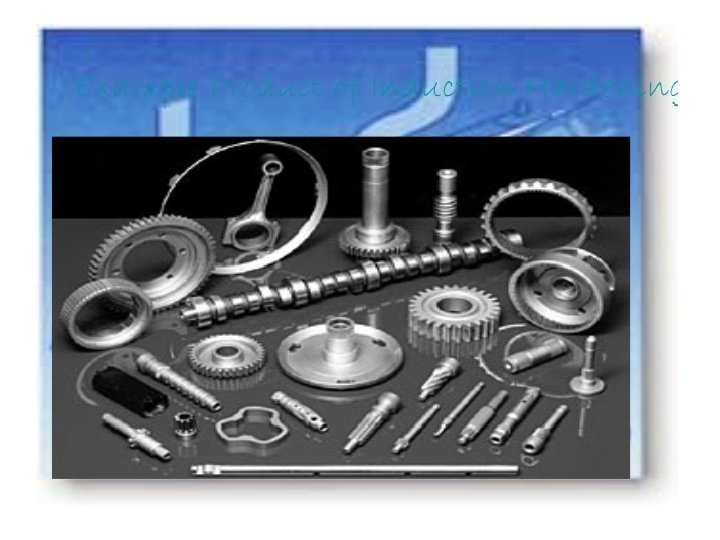
Heat treatment is the process of heating and cooling metals to change their microstructure and to bring out the physical and mechanical characteristics that make metals more desirable. The most common reasons metals undergo heat treatment are to improve their strength, hardness, toughness, ductility and corrosion resistance. Surface hardening is the process of hardening the surface of a metal object while allowing the metal deeper underneath to remain soft, thus forming a thin layer of harder metal (called the "case") at the surface. For example components like turbine shaft, gears, spindle, automotive components and axle need to have a hard surface but a soft core.

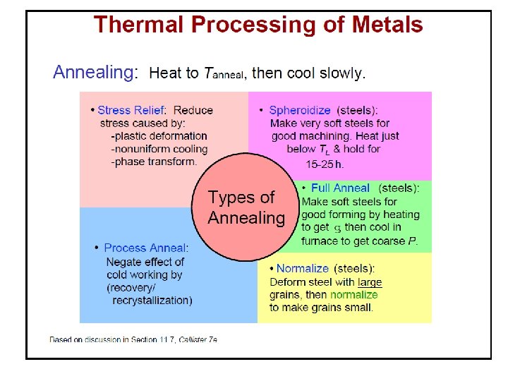
An overview of important heat treatments HEAT TREATMENT BULK ANNEALING NORMALIZING Full Annealing SURFACE HARDENING & TEMPERING MARTEMPERING Recrystallization Annealing Stress Relief Annealing Spheroidization Annealing THERMAL Flame Induction AUSTEMPERING LASER Electron Beam THERMOCHEMICAL Carburizing Nitriding Carbo-nitriding

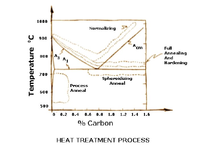
§ Ranges of temperature where Annealing, Normalizing and Spheroidization treatment are carried out for hypo- and hyper-eutectoid steels. § Normalizing Heat Treatment process is heating a steel above the critical temperature, holding for a period of time long enough for transformation to occur, and air cooling. Ful 910 C l A nne alin g Nor m aliz A 3 ali atio n rm o N io zat n Acm Full Annealing 723 C A 1 Stress Relief Annealing Spheroidization T Recrystallization Annealing Wt% C 0. 8 %

Through hardening of the sample q The surface of is affected by the quenching medium and experiences the best possible cooling rate. The interior of the sample is cooled by conduction through the (hot) sample and hence experiences a lower cooling rate. This implies that different parts of the sample follow different cooling curves on a CCT diagram and give rise to different microstructures. q This gives to a varying hardness from centre to circumference. Critical diameter (dc) is that diameter, which can be through hardened (i. e. we obtain 50% Martensite and 50% pearlite at the centre of the sample). Schematic showing variation in cooling rate from surface to interior leading to different microstructures
 Water Oil Air Turn")
Quenching media • • • Brine (water and salt solution) Water Oil Air Turn off furnace

Severity of quench values of some typical quenching conditions q Before we proceed further we note that we have a variety of quenching media at our disposal, with varying degrees of cooling effect. The severity of quench is indicated by the ‘H’ factor (defined below), with an ideal quench having a H-value of . Severity of Quench as indicated by the heat transfer equivalent H Process Variable H Air No agitation 0. 02 Oil quench No agitation 0. 2 " Slight agitation 0. 35 " Good agitation 0. 5 " Vigorous agitation 0. 7 Water quench No agitation 1. 0 " Vigorous agitation 1. 5 Brine quench (saturated Salt water) No agitation 2. 0 " Vigorous agitation 5. 0 Ideal quench Increasing severity of quench f → heat transfer factor K → Thermal conductivity Note that apart from the nature of the quenching medium, the vigorousness of the shake determines the severity of the quench. When a hot solid is put into a liquid medium, gas bubbles form on the surface of the solid (interface with medium). As gas has a poor conductivity the quenching rate is reduced. Providing agitation (shaking the solid in the liquid) helps in bringing the liquid medium in direct contact with the solid; thus improving the heat transfer (and the cooling rate). The H value/index compares the relative ability of various media (gases and liquids) to cool a hot solid. Ideal quench is a conceptual idea with a heat transfer factor of ( H = ).

Surface hardening: why & how? Components like gear, shaft or spindle need a hard / wear resistant surface but a soft / tough core. Section size of such components is often too large to be uniformly hardened even on severe quenching. More over the time lag between the transformations at the surface and the core results in an unfavorable tensile residual stress at the surface. Recall the general thumb rule that the region that transforms later is likely to have compressive residual stress. The surface is likely to transform first in steel having the same composition all through its section. Therefore surface would have residual tensile stress. Depending on its magnitude it may lead to cracking or distortion. The presence of residual tensile stress is also harmful as it would reduce fatigue life of critical components like turbine shaft or landing gear of an aircraft. The purpose of surface hardening is to develop a hard surface with compressive residual stress, to improve its wear resistance, to increase its fatigue life and to avoid susceptibility to distortion and cracking.

There are several other ways the strength or the hardness of the surface can be increased without adversely affecting the toughness of the core. Some of the most common techniques are as follows: 1. 2. 3. 4. 5. Induction hardening Case carburizing + case hardening Nitriding Shot peening Hard facing, coating or surface alloying Formation of Martensite is primarily responsible for the development of very high strength in steel. However you need to cool a component made of steel very fast to get martensite
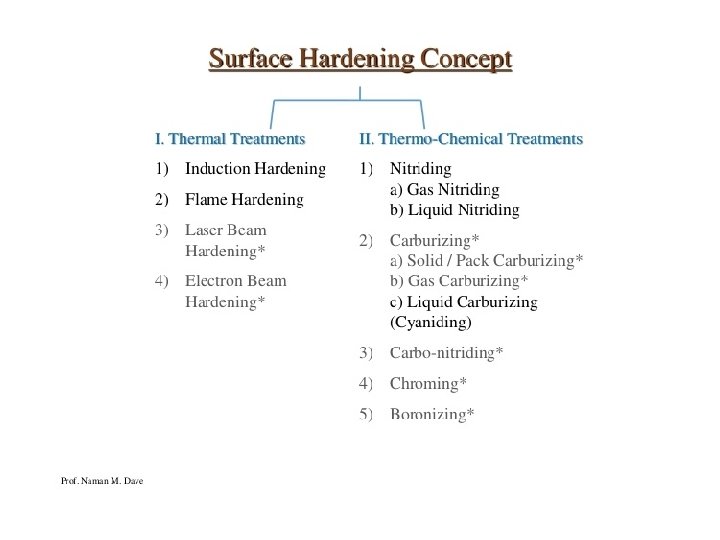
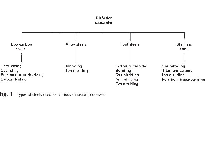

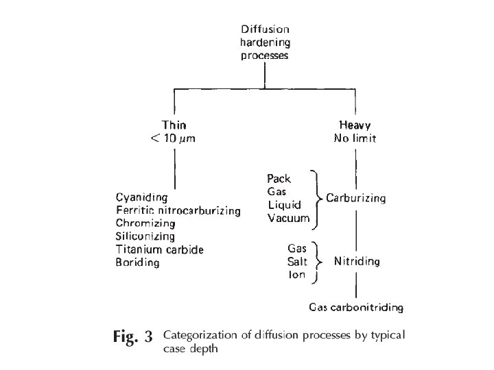
Engineering methods for surface hardening Layer additions Substrate treatment Hard‐facing Diffusion methods Fusion hard‐facing Carburizing Thermal spray Nitriding Coatings Carbonitriding Electrochemical plating Nitrocarburizing Chemical vapor deposition (electroless plating) Boriding Thin films (physical vapor deposition, Sputtering, ion plating) Titanium‐carbon diffusion Ion mixing Toyota diffusion process Selective hardening methods Flame hardening Induction hardening Laser hardening Electron beam hardening Ion implantation Selective carburizing and nitriding

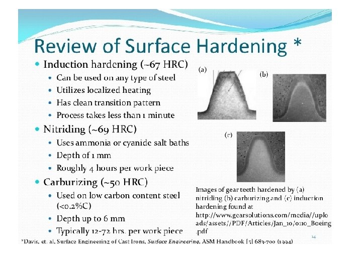
Induction hardening • Induced eddy currents heat the surface of the steel very quickly and is quickly followed by jets of water to quench the component. • A hard outer layer is created with a soft core. The slideways on a lathe are induction hardened.
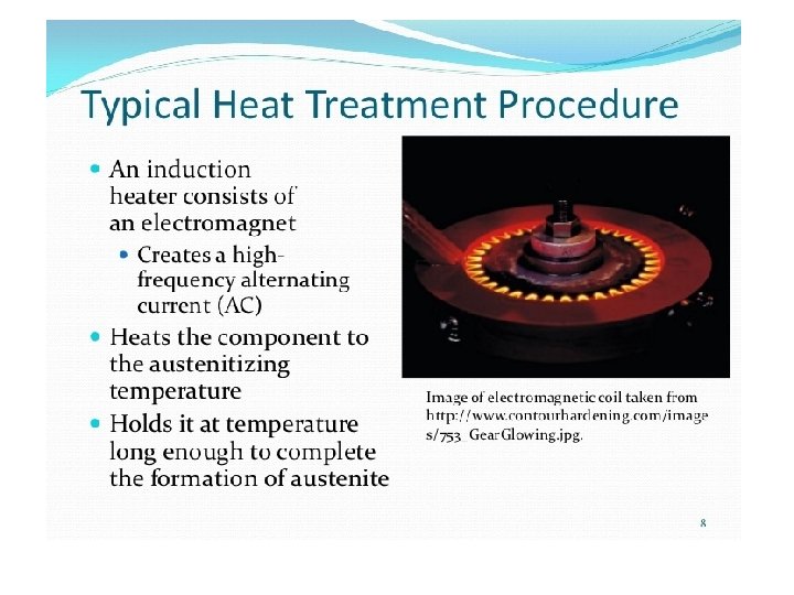
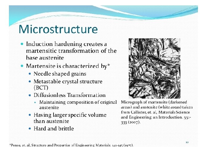

Induction hardening is very effective for surface hardening of plain carbon steel having 0. 35‐ 0. 70%C. The salient features of induction hardening are as follows: • Heat the surface to a temperature above A 3 (austenitic region) • Core does not get heated : the structure remains unaltered • Surface converts to martensite on quenching. • Fast heating & short hold time: needs higher austenization temperature • Martensite forms in fine inhomogeneous grains of austenite • Applicable to carbon steels (0. 35 – 0. 7 C) • Little distortion & good surface finish

Once the process is complete the microstructure of the surface gets transformed into martensite while that at its core remains unaltered.

Carburizing, also referred to as Case Hardening, is a heat treatment process that produces a surface which is resistant to wear while maintaining toughness and strength of the core. This treatment is applied to low carbon steel parts after machining as well as high alloy steel bearings, gears and other components. Carburizing increases strength and wear resistance by diffusing carbon into the surface of the steel creating a case while retaining a substantially lesser hardness in the core. This treatment is applied to low carbon steels after machining. Most carburizing is done by heating components in either a pit furnace, or sealed atmosphere furnace and introducing carburizing gases at temperature. Gas carburizing allows for accurate control of both the process temperature and carburizing atmosphere (carbon potential). Carburizing is a time/temperature process; the carburizing atmosphere is introduced into the furnace for the required time to ensure the correct depth of case. The carbon potential of the gas can be lowered to permit diffusion, avoiding excess carbon in the surface layer.

Carburizing cannot be done in ferrite phase as it has very low solid solubility for carbon at room temperature. It is done in the Austenite region above 727°C in carbon rich atmosphere. Types of carburizing i. Pack carburizing ii. Gas carburizing iii. Liquid carburizing For iron or steel with low carbon content, which has poor to no hardenability of its own, the case hardening process involves infusing additional carbon into the case. Case hardening is usually done after the part has been formed into its final shape, but can also be done to increase the hardening element content of bars to be used. Because hardened metal is usually more brittle than softer metal, through‐hardening (that is, hardening the metal uniformly throughout the piece) is not always a suitable choice for applications where the metal part is subject to certain kinds of stress. In such applications, case hardening can provide a part that will not fracture (because of the soft core that can absorb stresses without cracking) but also provides adequate wear resistance on the surface.

Pack carburizing • The component is packed surrounded by a carbon‐rich compound and placed in the furnace at 900 degrees. • Over a period of time carbon will diffuse into the surface of the metal. • The longer left in the furnace, the greater the depth of hard carbon skin. Grain refining is necessary in order to prevent cracking. A major limitation of pack carburizing is poor control over temperature & carburization depth. On completion of the process the steel parts are cooled slowly. Direct quenching is not possible as the job is surrounded by carburizing mixture packed in a sealed box having high thermal mass. This can be overcome by using gaseous or liquid carburizing medium.

• Salt bath carburizing. A molten salt bath (sodium cyanide, sodium carbonate and sodium chloride) has the object immersed at 900 degrees for an hour giving a thin carbon case when quenched. • Gas carburizing. The object is placed in a sealed furnace with carbon monoxide allowing for fine control of the process. • Gas carburization is done by keeping the samples at the carburizing temperature for a specified time in a furnace having a mixture of carburizing and neutral gas. CH 4 and CO are the most commonly used carburizing gas. • It is usually mixed with de‐carburizing (H 2 and CO 2) and neutral gases (N 2). • This helps maintain a close control over carbon potential. It should be enough to maintain %C at in the range 1. 0‐ 1. 2% at the surface. • In the presence of Fe the carburizing gases decompose to produce nascent carbon that diffuses into steel. CH 4 = C (Fe) + 2 H 2 2 CO = C (Fe) + CO 2 • It provides excellent control over the furnace temperature and atmosphere (carbon potential). • Samples after carburization can be directly quenched.

Liquid carburization It is done by keeping the job in a salt bath consisting of 8% Na. CN + 82 Ba. Cl 2 + 10 Na. Cl. It allows precise temperature control and rapid heat transfer. Carburization takes place due to the formation of nascent carbon. The chemical reactions that occur in the presence of Fe are as follows: Ba. Cl 2 + Na. CN = Ba(CN)2 +Na. Cl Ba(CN)2 = C (Fe) + Ba. CN 2 What is the chemical CN? A cyanide is a chemical compound that contains the group C≡N. This group, known as the cyano group, consists of a carbon atom triple‐bonded to a nitrogen atom. The sample can be quenched immediately after carburization. Nitriding Nitrides are formed on a metal surface in a furnace with ammonia gas circulating at 500 degrees over a long period of time (100 hours). It is used for finished components. If steel is heated in an environment of cracked ammonia it picks up nitrogen. Nitrogen like carbon forms interstitial solid solution with iron. If it is present in excess it forms nitride (Fe 4 N). It is extremely hard and brittle.

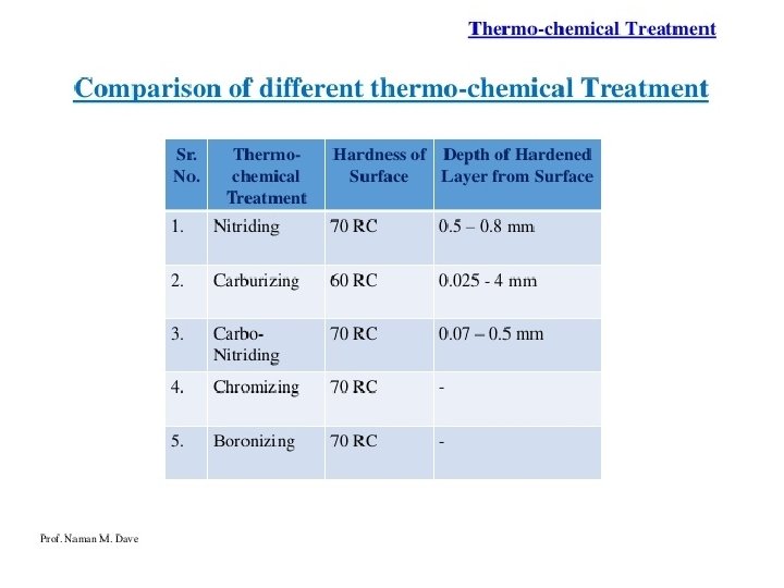
Nascent nitrogen that forms at the surface of steel as ammonia comes in contact with Fe. This diffuses into iron lattice and form nitride as and when the amount of nitrogen in steel exceeds its solubility limit. The presence of alloying elements having high affinity for nitrogen increases nitrogen pick up. The formation of nitride within the matrix results in a substantial increase in the hardness of steel. The preferred thickness of the hardened layer is around 20 micro meter. The hardness of the nitride layer is usually in the range of 1000‐ 2000 Hv. Nitriding of steel is carried out only after it has been hardened and tempered. It is the last heat treatment given to steel.

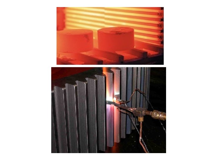
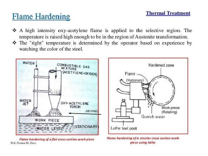
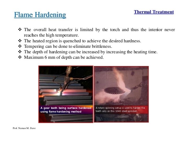
Flame hardening • Gas flames raise the temperature of the outer surface above the upper critical temp. The core will heat by conduction. • Water jets quench the component.
 – Thermal PVD – Sputter Deposition –")
Vapor Deposition • Physical Vapor Deposition (PVD) – Thermal PVD – Sputter Deposition – Ion plating • Chemical Vapor Deposition (CVD)

Physical Vapor Deposition – Thermal PVD • Thermal PVD – also called Vacuum Deposition – Coating material (typically metal) is evaporated by melting in a vacuum – Substrate is usually heated for better bonding – Deposition rate is increased though the use of a DC current (substrate is the anode so it attracts the coating material) – Thin ~0. 5 mm to as thick as 1 mm.

Physical Vapor Deposition – Sputter Deposition • Vacuum chamber is usually backfilled with Ar gas • Chamber has high DC voltage (2, 000‐ 6, 000 V) • The Ar becomes a plasma and is used to target the deposition material. The impact dislodges atoms from the surface (sputtering), which are then deposited on the substrate anode • If the chamber is full of oxygen instead of Ar, then the sputtered atoms will oxidize immediately and an oxide will deposit (called reactive sputtering)

Physical Vapor Deposition – Ion Plating • Combination of thermal PVD and sputtering • Higher rate of evaporation and deposition • Ti. N coating is made this way (Ar‐N 2 atmosphere) – The gold looking coating on many cutting tools to decrease the friction, increase the hardness and wear resistance
 produced by a vapor‐phase")
Chemical Vapor Deposition • Deposition of a compound (or element) produced by a vapor‐phase reduction between a reactive element and gas – Produces by‐products that must be removed from the process as well • Process typically done at elevated temps (~900ºC) – Coating will crack upon cooling if large difference in thermal coefficients of expansion – Plasma CVD done at 300‐ 700ºC (reaction is activated by plasma) • Typical for tool coatings • Applications – Diamond Coating, Carburizing, Nitriding, Chromizing, Aluminizing and Siliconizing processes – Semiconductor manufacturing

Plasma Nitriding Plasma nitriding, also known as ion nitriding or glow discharge nitriding, is a gas nitriding process enhanced by a plasma discharge on the part to be nitrided. The plasma is gas that when exposed to an electrical potential is ionized and glows. The parts to be nitrided are connected as a cathode and the furnace walls are the anode. They are supplied with a potential between 0. 3 and 1 KV. Particles are accelerated and hit the cathode (work piece) transferring all their kinetic energy and heating it. For gas particles to have enough kinetic energy to transfer, they need to have a considerable large mean free path and in this way gain speed for collision with the substrate before colliding with another gas particle. This is why this process and mostly all plasma processes work under vacuum as a measure to increase the mean free path of the accelerated particles. The pressure used for plasma nitriding is normally between 100 – 1000 Pa. Other authors suggest a narrower range between 50 – 500 Pa. This pressure is considered as a rough vacuum since there are other processes that use much higher vacuum values.

The chemical reaction when ammonia dissociated was explained in the preceding section. In the case of plasma nitriding, the process gases are introduced separately. One combination that is often used is Nitrogen + Hydrogen. Argon is also used in the initial stages as a plasma sputtering gas for surface cleaning of the substrate to be nitrided. The voltage drop occurs in what is called the plasma sheath which is a positive charged area where ions are accelerated towards the cathode and have their highest kinetic energies.

During ion nitriding three reactions will occur at the surface of the material being treated. In the first reaction, iron and other contaminants are removed from the surface of the work by an action known as sputtering or by a reducing reaction with hydrogen. The impact of hydrogen or argon ions bombarding the work surface dislodges the contaminant that will be extracted by the vacuum system. The removal of these contaminants allows the diffusion of nitrogen into the surface During the second reaction, and as a result of the impact of the sputtered ion atoms, case formation begins at the work surface of iron nitrides. Sputtered Fe + N = Fe. N During the third reaction, a breakdown of the Fe. N begins under the continuous sputtering from the plasma. This one causes the instability of the Fe. N which begins to break down into the e phase followed by the g’ phase and a iron‐nitrogen compound zone

There are following types of surface treatments. Surface Treatment Type Concepts and Applications of the process Electroplating A method of forming metallic coatings (plating films) on subject metal surfaces submerged in solutions containing ions by utilizing electrical reduction effects. Electoplating is employed in a wide variety of fields from micro components to large products in information equipment, automobiles, and home appliances for ornamental plating, anti‐corrosive plating, and functional plating. Electroless Plating A plating method that does not use electricity. The reduction agent that replaces the electricity is contained in the plating solution. With proper re‐processing, virtually any material such as paper, fabrics, plastic and metals can be plated, and the distribution of the film thickness is more uniform, but slower than electroplating. This is different from chemical plating by substitution reaction. Chemical Process (Chemical Coating) The process creates thin films of sulfide and oxide films by chemical reactions such as post zinc plating chromate treatment, phosphate film coating (Parkerizing), black oxide treatments on iron and steels, and chromic acid coating on aluminum. It is used for metal coloring, corrosion protection, and priming of surfaces to be painted to improve paint adhesion. Anodic Oxidation Process This is a surface treatment for light metals such as aluminum and titanium, and oxide films are formed by electrolysis of the products made into anodes in electrolytic solutions. Because the coating (anodizing film) is porous, dyeing and coloring are applied to be used as construction materials such as sashes, and vessels. There is low temperature treated hard coating also. Hot Dipping Products are dipped in dissolved tin, lead, zinc, aluminum, and solder to form surface metallic films. It is also called Dobuzuke plating and Tempura plating. Familiar example is zinc plating on steel towers. Vacuum Plating Gasified or ionized metals, oxides, and nitrides in vacuum chambers are vapor deposited with this method. Methods are vacuum vapor deposition, sputtering, ion plating, ion nitriding, and ion implantation. Titanium nitride is of gold color. Painting There are spray painting, electrostatic painting, electrodeposition painting, powder painting methods, and are generally used for surface decorations, anti‐rusting and anti‐corrosion. Recently, functional painting such as electro‐conductive painting, non‐adhesive painting, and lubricating painting are in active uses. Thermal Spraying Metals and ceramics (oxides, carbides, nitrides) powders are jetted into flames, arcs, plasma streams to be dissolved and be sprayed onto surfaces. Typically used as paint primer bases on larger structural objects, and ceramic thermal spraying for wear prevention. Surface Hardening This is a process of metal surface alteration, such as carburizing, nitriding, and induction hardening of steel. The processes improve anti‐ wear properties and fatigue strength by altering metal surface properties. Metallic Cementation This is a method of forming surface alloy layers by covering the surfaces of heated metals and metal diffusion at the same time. There is a method of heating the pre‐plated products, as well as heating the products in powdered form of metal to be coated.

What is meant by Austempering? Austempering is heat treatment that is applied to ferrous metals, most notably steel and ductile iron. In steel it produces a bainite microstructure whereas in cast irons it produces a structure of acicular ferrite and high carbon, stabilized austenite known as ausferrite. What is Martempering process? Martempering is a heat treatment for steel involving austenitisation followed by step quenching, at a rate fast enough to avoid the formation of ferrite, pearlite or bainite to a temperature slightly above the martensite start (Ms) point.

Thank You. . For your Patient listening
- Slides: 48