Surface Drainage With Trench Drains Alaska DOT ACO


 Invert")


 • Load Class")
 4 foot channels x 25 • 25 sloping channels •")

")

 Cast Iron top with polymer concrete base unit. End")


 Lightweight Scuppers help reduce overall bridge weight FG-200 Grate 6”")
 Angle Branch Scupper entry 6” pipe system 45° Bend Solvent")
 Rock Island, Illinois Rock Island Arsenal Bridge")


- Slides: 43
Surface Drainage With Trench Drains Alaska DOT ACO Polymer Products Jeff Lipp
1. ACO - Global Surface Drainage experts ACO GROUP • ACO, established 1946 • Today we are in 24 countries • 18 Manufacturing plants on 4 continents • 3, 400 employees • The World’s largest producer of Polymer Concrete • ACO USA The pioneer and first modular trench drain company in the USA (1978) • Manufacturing in Ohio, Iowa • Stock and Sales centers in Ohio, California • Distribution in every state
Methods of Surface Drainage 1. Catch Basin Drainage • • • Complex grades Installation time Ponding Excessive pipe work Maintenance difficulties • • High grate and frame cost Hidden installation costs Erratic quality Variable life expectancy • • Versatile Quick to install Low installation costs Consistent factory quality • • • Low cost Irregular surface Poor hydraulics Easily blocked by debris Requires frequent maintenance $$ 2. Trench Drainage A. Cast in Place B. Pre-cast Modular C. Open Swale
ACO Drain - Modular System Solutions • Modular, lightweight, pre-cast units made from Polymer Concrete or Fiberglass • Units made with male and female alignment joints • Choice of pre-sloped or constant depth systems • Closing end caps, outlet end caps and catch basins available • Wide choice of Grates • Captive and locked Grates • Variety of systems for all applications ACO is the inventor and a pioneer of modular, pre-sloped trench drain systems
HYDRAULIC PERFORMANCE – Outlet options Size, position and type of outlet determine trench capacity – incorrectly sized outlets ‘throttle’ flow in trench and cause flooding. Size outlet to suit trench AND underground pipe work. Types of outlet: 1. 2. 1. End outlet – connected horizontally trench end. Poor hydraulic performance - low capacity, compared to trench, - low velocity of flow. Use in limited space applications 2. Bottom outlet – connected vertically to trench bottom. Offers better 3. hydraulics due to gravity. 3. In-line catch basin – similar width to trench, but deeper - trash bucket collects debris. Better hydraulics, larger outlet pipes can be used, increased depth gives head of water. Discrete installation 4. Catch basin – large basin, wider than trench, trash bucket collects debris. Best hydraulics, large outlet pipe used and increased depth gives head of water. Large size gives good access to pipes. Correct pipe size should be determine by the outflow of trench. 4.
HYDRAULIC PERFORMANCE - Trench Correct profile option Drain Options – Neutral v Slope is determined by location. Neutral invert – zero ground fall Invert depth of trench parallel to top edge of trench (ground surface level) • Depth restrictions – e. g. . elevated slab applications Neutral invert – ground fall Ground slope of pavement same as trench base (invert) slope • Ground slope generates flow velocity • Improved hydraulic performance Sloped Invert – zero ground fall Slope at base of trench (invert) gets deeper compared to top edge (ground surface level) • Trench invert slope generates flow velocity • Improved hydraulic performance Sloped Invert – ground fall Ground slope and additional slope at base of trench • Trench invert slope generates flow velocity • Increased hydraulic performance
HYDRAULIC PERFORMANCE - Some basic points Overall trench dimension Finished floor level (elevation) Invert of trench, usually referred to as invert elevation Rounded or Vee bottom to trench Overall grate dimension Clear area available for flow Trench CLEAR opening dimension • Generally clear opening is specified dimension • If modular trench drains are used, clarify clear opening available – some products state ‘overall trench’ size misleading specifiers to clear area available for flow Example: a 4 inch trench has a 4 inch wide clear opening, but may have a 5 or 6 inch overall dimension • Rounded or Vee bottoms maximize velocity when liquid levels are low • The ‘clear area’ determines hydraulics – clear opening x invert depth (less thickness of grate)
LOADING - Load standards DIN 19580 – Trench system Test Specifiers ensure products are ‘fit for purpose’. Products should be independently certified, and relate to a relevant standard. There is currently NO American test standard that covers ALL trench drain sizes and applications. Most standards are written for large catch basins. Commonly referred to: DIN 19580 – 4” Grate Test • ASME A 112. 21. 1 M - 1991 Plumbing specification relating to internal drains • AASHTO Standard specification for highway bridges - Load details for bridge design • A-A 60005 Federal Specification - Frames, covers, gratings, steps, sump and catch basin, manhole castings General product specs • FAA AC: 150/5370 -10 item D-751 Manholes, catch basins, Inlets and Inspection holes - Airport product and material specs Currently the only international standard written specifically for trench drains is DIN 19580 (EN 1433 to supersede) DIN 19580 – 8” Grate Test
LOADING – Understanding load testing Gratings are subjected to ‘BENDING’ loads. Trench drain bodies are subject to COMPRESSIVE loads. Tests should represent these conditions. Grate testing is the most important, and most often misrepresented. Grate testing – Understand the test! DIN TEST - test block (3”x 10”) applied to a 6 inch wide grate (to fit 4 inch clear opening trench) – bending pressure is applied to grate Same grate subject to test load applied through 9”x 9” test block. Grate NOT being tested. Supports are taking load!
Polymer Concrete • Mineral aggregates bound with polymer resin • Compressive strength four times Cement concrete • Unaffected by most acids and alkalis • Almost zero water absorption • Smooth, impervious surface
Other Common Trench Drain Materials Fiberglass • Glass mat bound with polymer resin • Strong lightweight material • Excellent chemical resistance • Zero water absorption • Very smooth, impervious surface Molded Plastic • Injection molded process • Durable, flexible lightweight material • Excellent chemical resistance • Low water absorption • Smooth, impervious surface • Stability issues
DURABILITY – Trench material Thermal Freeze-thaw Surface Friction Compressive summary Expansion breakdown Hydraulics Strength Chemical Resistance Cement concrete Polymer concrete Fiberglass Plastic Thousands inch/F Inches/72 Hrs Micro inches Cement Concrete Low High Good with sufficient mass Low Polymer Concrete Low High Fiberglass Low High Plastic High Low High
Concrete fabrications
Concrete fabrications
Cost of Surface Drainage Cost is a critical influence. To estimate total installed cost of surface drainage, consider all material and labor costs. An example of 3 surface drainage options for a 136, 700 sf parking lot. Catch Basins Cast in Place Pre-cast Modular • Site work - excavation, including trenches for connecting pipe work - 14% of total cost • Site work - excavation including trenches for connecting pipe work and formwork (material & labor) - 22% of total cost • Site work - excavation, including trenches for connecting pipe work 12% of total cost • Concrete Surrounds - 14% • Concrete Surrounds - 18% • Concrete Surrounds - 4% • Pipe and fittings - 47% • Pipe and fittings - 20% • Catch basins, grate and frame etc. - 35% • Grate and Frame - 44% - • Pipe and fittings - 20% • Pre-cast Modular Drains - 50% Cost comparison for all 3 methods in index form Cost Comparison Index = 1. 00 Cost Comparison Index = 1. 09 Cost Comparison Index = 0. 89
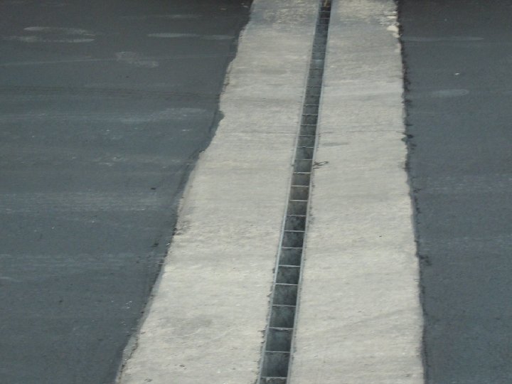
Story of Trench Drain at DOT • Typically DOT’s have used slotted pipe which silt up and are hard to clean • Utah I 15, MDOT, I 75 and I 94. Cost of trench drain compared to cost of excavation and elevation changes that would be needed to use the traditional CB • Save money using TD by extending distance between CB or saving $$ on the re -grading costs. Typical CB cost in excess of $15, 000
Story of Trench Drain at DOT • Installation on I 75 was 1000 feet per day. • Installation for I 94 looking at 1300 lf per day • Flow rates. On specification sheets. TD has two options; slotted vs high capacity • Caltran 13, 000 lf. Chumno 91 frwy • TD also supply a safety factor along drainage area
Introducing A New Family of ACO Products § Traffik. Drain § Highway. Drain § Curb. Drain § Bridge. Drain - Piping § Bridge. Drain - Scupper
Initial Announcement Came in the form of an advertisement placed in Interstate 50 , a publication celebrating 50 years of the American Interstate System.
1. Traffik. Drain 60% open intake area • Based on Power. Drain S 100 K body • 30 -1 meter sloped units • 4 neutral units • Half meter units • Full Group of Accessories Dutile Iron Grates have two bolts per half meter
1. Traffik. Drain Two piece molded plastic flumed outlet New 8” Outlet
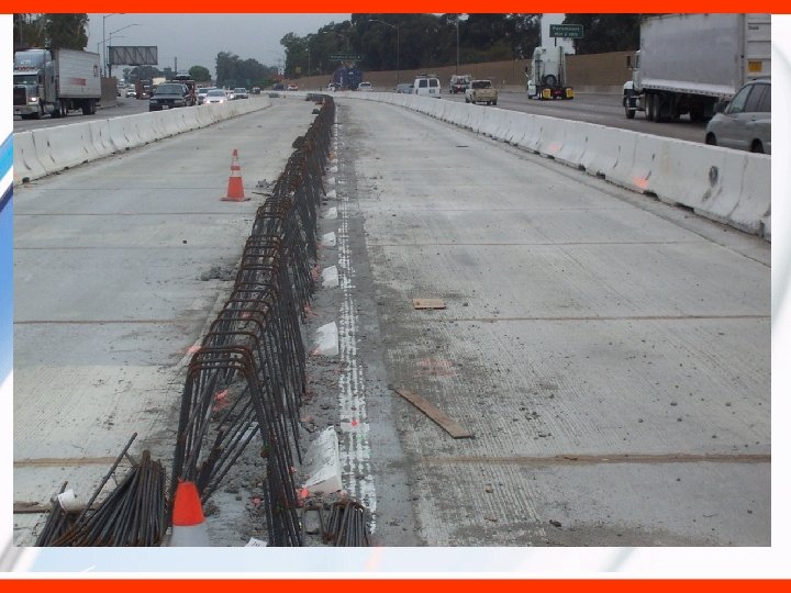
HYDRAULIC PERFORMANCE – Case • Road grading created cross road water flow causing Study – ‘Using to save lives’ traffichydraulics accidents. • Solution was to install trench drain in central median strip. • Trench hydraulic calculations and grate intake calculations were carried out. • Due to road steepness or cambers in some areas, large trench’s were required. A more cost effective solution was to use double runs of smaller trench’s. • No accidents were reported in the following 5 years Summary: Hydraulics used to achieve safest and most cost effective solution
1. Traffik. Drain in Ohio
1. Traffik. Drain in Michigan
New 2. Highway. Drain Features: • Monolithic Design (100% polymer concrete) • Load Class E (H-20 and above) • 4 foot drain channels ( Full 8” I. D. ) • 25 sloped channels (100 ft. @. 6%) • 3 neutral channels • 30% water intake • Cleanout available ( bolted D. I. grate & frame)
2. Highway. Drain (system) 4 foot channels x 25 • 25 sloping channels • 3 non-sloping channels • Non-sloping channels can be fitted with flume outlet • Non-sloping channels can be fitted with inspection/cleanout grate & frame
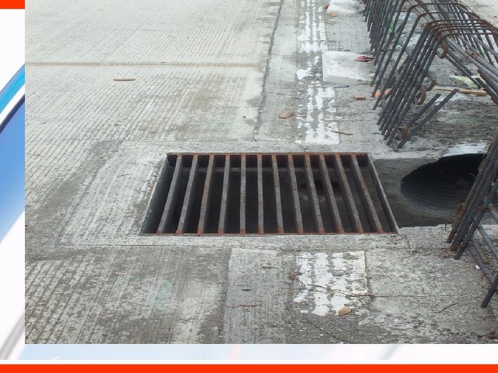
2. Highway. Drain Horizontal Outlet Adapter Flumed Outlet Adapter Vertical Outlet Adapter
2. Highway. Drain Applications • Cross Drains • High Speed (On/Off Ramps & Medians) • Toll Plazas • Temporary D. O. T. Crossovers • Service Stations / Truck Stops • Chemical Plants (non-metallic)
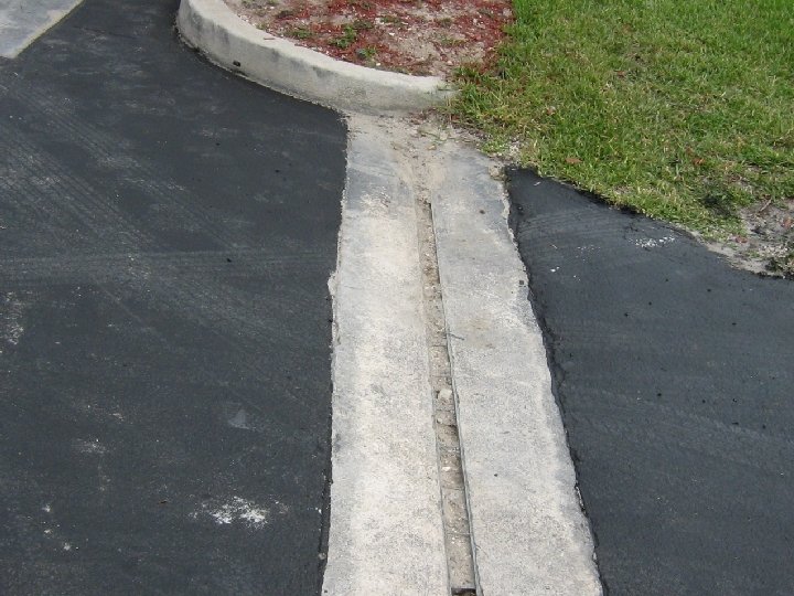
3. Curb. Drain Features • 24” polymer concrete units • Monolithic design • 2 inlets per unit (1 opening every 12”) • Polymer Catch Basin (with Cast Iron top) • Inspection/Cleanout Unit Available • Radius & Corner Units New
3. Curb. Drain (System ) Cast Iron top with polymer concrete base unit. End Cap Radius Curb. Drain RH Drop Curb. Drain with Inspection Cover Center Stone – 3 types LH Drop Curb. Drain Corner Unit
• Curb drain
Client Needs
Client Needs
4. Bridge. Drain (scupper) Lightweight Scuppers help reduce overall bridge weight FG-200 Grate 6” Outlet Fiberglass body
4. Bridge. Drain (piping) Angle Branch Scupper entry 6” pipe system 45° Bend Solvent weld bell & spigot connection 30° Bend Filament wound pipe bodies New Cleanout Access 90° Bend
4. Bridge. Drain (piping) Rock Island, Illinois Rock Island Arsenal Bridge
ACO Wildlife
ACO Wildlife
A Message From the President In my 20 years of senior ACO management through North America, Australia and the United Kingdom I have witnessed and experienced relationships with many distributors in this industry. Some stand out over others, but the one between ACO & White Cap Construction Supply is a shining example of a healthy and profitable manufacturerdistributor relationship. In 2002 the relationship between White Cap and ACO began in earnest. As with any relationship there have been a few bumps in the road along the way. I have observed eagerness on both sides to eliminate those obstacles and develop a willingness to work together for mutual success. On behalf of all the employees of ACO USA, Chris, Tom, Ray and I would like to thank you for helping ACO to remain the premier modular trench drain in the market. We pledge our continued support through extensive marketing efforts, trade shows, A & E specification calls, technical support from internal staff, and of course our area sales managers and manufacturers representatives. • • All of us here at ACO appreciate the excellent job White Cap does in promoting ACO Drain and we continue to look forward to working with you to sustain profitable growth. Sincerely; Derek Humphries President, ACO Polymer Products, Inc. & CEO of ACO Pan Pacific Group