SuperB Accelerator Overview J Seeman With contributions from

Super-B Accelerator Overview J. Seeman With contributions from the Super-B Contributors Super-B Workshop at SLAC October 6, 2009

Outline • • Overview Super-B parameters Frascati DAFNE crab waist results Interaction region Lattice Polarization PEP-II reusable components Conclusions

e+e- Colliders Super Factories Linear colliders Factories B-Factories Future Colliders

Super-B Project • Super-B aims at the construction of a very high luminosity (1 x 1036 cm-2 s− 1) asymmetric e+e− flavor factory with a possible location on or near the campuses of the University of Rome at Tor Vergata or the INFN Frascati National Lab. • Aims: – – – Very high luminosity (~1036) Flexible parameter choices. High reliability. Longitudinally polarized beam (e-) at the IP (>80%). Ability to collide at the Charm threshold.
 • • D. Alesini, M. E. Biagini, R.")
Super-B Accelerator Interested Contributors (~Fall 2009) • • D. Alesini, M. E. Biagini, R. Boni, M. Boscolo, A. Clozza, T. Demma, A. Drago, M. Esposito, A. Gallo, S. Guiducci, V. Lollo, G. Mazzitelli, C. Milardi, L. Pellegrino, M. Preger, P. Raimondi, R. Ricci, C. Sanelli, G. Sensolini, M. Serio, F. Sgamma, A. Stecchi, A. Stella, S. Tomassini, C. Vaccarezza, M. Zobov (INFN/LNF, Italy) K. Bertsche, A. Brachmann, Y. Cai, A. Chao, A. De. Lira, M. Donald, A. Fisher, D. Kharakh, A. Krasnykh, N. Li, D. Mac. Farlane, Y. Nosochkov, A. Novokhatski, M. Pivi, J. Seeman, M. Sullivan, U. Wienands, J. Weisend, W. Wittmer, G. Yocky (SLAC, US) A. Bogomiagkov, S. Karnaev, I. Koop, E. Levichev, S. Nikitin, I. Nikolaev, I. Okunev, P. Piminov, S. Siniatkin, D. Shatilov, V. Smaluk, P. Vobly (BINP, Russia) G. Bassi, A. Wolski (Cockroft Institute, UK) S. Bettoni (CERN, Switzerland) M. Baylac, J. Bonis, R. Chehab, J. De. Conto, Gpmez, A. Jaremie, G. Lemeur, B. Mercier, F. Poirier, C. Prevost, C. Rimbault, Tourres, F. Touze, A. Variola (CNRS, France) A. Chance, O. Napoly (CEA Saclay, France) F. Bosi, E. Paoloni (Pisa University, Italy)
 • • Italy: 7 FTE US: 5")
Present Super-B Accelerator FTE Contributors (~Fall 2009) • • Italy: 7 FTE US: 5 FTE Russia: 3 FTE France: 1 FTE

How to get 100 times more Luminosity equation y Ib n y * E Vertical beam-beam parameter Bunch current (A) Number of bunches IP vertical beta (cm) Beam energy (Ge. V) Present day B-factories PEP-II E(Ge. V) 9 x 3. 1 Ib 1 x 1. 6 n 1700 I (A) 1. 7 x 2. 7 y* (cm) 1. 1 y 0. 08 0. 11 L (x 1034) 1. 2 Answer: Increase Decrease Increase KEKB 8 x 3. 5 0. 75 x 1 1600 1. 2 x 1. 6 0. 6 2. 0 Ib y* y n
 •")
Crab Waist Scheme (Raimondi) •

Beam distributions at the IP Crab sextupoles OFF Without waist line is orthogonal Crab-sextupoles to the axis of one bunch Crab sextupoles ON With Crab-sextupoles waist moves to the Paoloni axis of. E. other beam All particles from both beams collide in the minimum y region, with a net luminosity gain

Crossing Angle Test at DAFNE
![Data averaged for a full day Luminosity [1028 cm-2 s-1] y=9 mm, Pw_angle=1. 9](http://slidetodoc.com/presentation_image_h2/2e5b231ea395f9d49c345bec9619a091/image-11.jpg "Data averaged for a full day Luminosity [1028 cm-2 s-1] y=9 mm, Pw_angle=1. 9")
Data averaged for a full day Luminosity [1028 cm-2 s-1] y=9 mm, Pw_angle=1. 9 y=25 mm, Pw_angle=0. 3

Super-B Parameter Options •
 Parameter V 1 (22. 07. 09) V")
Parameters of Super. B lattices (September 2009) Parameter V 1 (22. 07. 09) V 2 (1. 09) V 3 (9. 09) HER LER 6. 7 4. 18 Circumference L, m 1315. 65 1315. 57 1327. 81 1328. 85 Number of particles, *1010 5. 74 Hor. tune Qx 43. 575 Ver. tune Qy 18. 595 Energy Eo, Ge. V Emittance Em, nm*rad 1. 6 2. 56 2. 04 2. 2 2. 07 Coupling 0. 25 6. 15 E-04 6. 57 E-04 6. 16 E-04 Longitudginal length, mm 5 5 5 Damping time x / s, msec 29 / 14. 5 44 / 22 29 / 14. 5 Beta_X_IP, cm 2 3. 2 2 Beta_Y_IP, cm 0. 032 0. 02 1. 06 1. 11 1. 07 1. 04 /1. 02 1. 239 / 1. 109 1. 04 /1. 02 Energy spread, Sig_p R( hourglass factor) 0. 9 IBS tranc / long , Aibs/Ao Toush. Lifetime, min 35 16 37 17 39 Acceptance of energy, % 1. 5 1. 21 1. 5 1. 22 S. Siniatkin

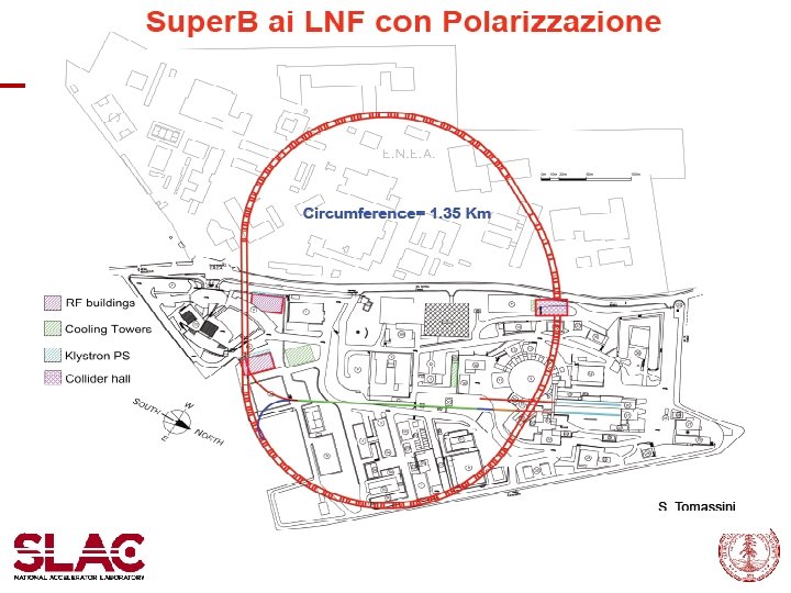
Super. B Site Choices C ~1. 35 km Frascati National Laboratories Existing Infrastructure

Vibration studies at LNF Frascati Tomassini

Collider Hall Roman Villa Super. B LINAC SPARX Super. B footprint at Tor Vergata Storage rings length = 1800 m

Perspective view

Tunnel Layout • Tomassini, Saneli
 0. 45 5. 4 PEP HER - 194")
Layout: PEP-II magnets reuse Lmag (m) 0. 45 5. 4 PEP HER - 194 PEP LER 194 - Available SBF HER - 130 Needed SBF LER 224 18 SBF Total 224 148 Needed 30 0 Dipoles Quads Lmag (m) 0. 25 0. 5 PEP HER/LER 188 - SBF Total 372 4 Needed 184 4 Sexts Lmag (m) 0. 56 0. 73 0. 43 0. 7 0. 4 PEP HER 202 82 - - - PEP LER - - 353 - - SBF HER 165 108 - 2 2 SBF LER 88 108 165 2 2 SBF Total 253 216 165 4 4 Needed 51* 134 0 4 4 All PEP-II magnets can be used, dimensions and fields are in range RF requirements are met by the present PEP-II RF system

PEP-II Magnets and RF Components •

Arc Lattice • • • Raimondi, Biagini, Wittmer, Wienands Arc cell: flexible solution is based on decreasing the natural emittance by increasing mx/cell, and simultaneously adding weak dipoles in the cell drift spaces to decrease synchrotron radiation All cells have: mx=0. 75, my=0. 25 about 30% fewer sextupoles Better DA since all sextupoles are at –I in both planes (although x and y sextupoles are nested) Distances between magnets compatible with PEP-II hardware All quads-bends-sextupoles in PEP-II range Arcs & FF

W. Wittmer •
 (Sept 2009) • Y. Nosochkov")
Lattice Layout (Two Rings) (Sept 2009) • Y. Nosochkov

HER functions Y. Nosochkov

LER functions in the dogleg Y. Nosochkov
. Ex = 5. 6 nm Fig. 2 Modificated Dogleg")
Dogleg section. LER&HER (V 3). Ex = 5. 6 nm Fig. 2 Modificated Dogleg section. LER&HER. (New) Ex = 2. 2 nm Fig. 3 S. Siniatkin

Twiss function studies - increasing separation between horizontal and vertical beta functions. It is result to changing of compensation sextupole scheme; Fig. 8 S. Siniatkin

Arc cell & Scheme of sextupole compensation Fig. 12 Arc cells contain three family of sextupoles. First family compensate of chromaticity of experimental section. Second family compensate of chromaticity of arc cells and third family – chromaticity of technical section. S. Siniatkin
 IP CRAB Additional Main sext Correction sext correction sext Main sext")
DA calculations (preliminary) IP CRAB Additional Main sext Correction sext correction sext Main sext Correction sext P. Piminov
 1000 Sigma. Y 350 Sigma. X Only Main Sexts P. Piminov")
Optimized DA (Preliminary) 1000 Sigma. Y 350 Sigma. X Only Main Sexts P. Piminov Chromatic funcs @ IP: Wx=3. 8 Wy=12. 8 Wx=11. 3, Wy=450!
 E (Ge. V) C (m) g")
Comparison of design and achieved beam emittances (*achieved) E (Ge. V) C (m) g ex (nm) gex (mm) ey (pm) gey(nm) Spring-8 8 1430 15656 6 94 5 78 ILC-DR 5 6400 9785 1 10 2 20 Diamond* 3 561 5871 2. 7 16 2 29 ATF* 1. 28 138 2524 1 2. 5 4 10 SLS* 2. 4 288 4700 6 28 3. 2 15 Super. B LER 4 1800 7828 2. 8 22 7 55 Super. B HER 7 1800 13699 1. 6 22 4 55 Emittance tuning techniques and algorithms have been tested in simulations and experiments on the ATF and on the other electron storage rings to achieve such small emittances (ex. Cesr. TA as an ILC-DR test facility has a well established one).
, ICFA 08 Workshop Typical case (KEKB, DAFNE): Much")
x-y resonance suppression D. Shatilov’s (BINP), ICFA 08 Workshop Typical case (KEKB, DAFNE): Much higher luminosity! Crab Waist On: 1. low Piwinski angle F < 1 1. large Piwinski angle F >> 1 2. y comparable with sz 2. y comparable with sx/q
 Fy (Crabbed, Z=2 cm)")
Crabbed Strong Beam, Pictures: Beam-Beam Kick Fy (Gaussian, Z=2 cm) Fy (Crabbed, Z=2 cm) Fy (Gaussian, Y=-0. 5 σy) D. Shatilov Fy (Crabbed, Y=-0. 5 σy)
 •")
Polarization versus Energy of HER (Wienands) •

Calculation of the steady longitudinal polarization degree for the 2009 Super. B project (LER E=4. 18 Ge. V) • • SLAC-Frascati variant of the spin rotator insertion Betatron contribution account based on S. Nikitin/SB-NOTE-ACC- 2008 - 001 S. A. Nikitin 21. 09
")
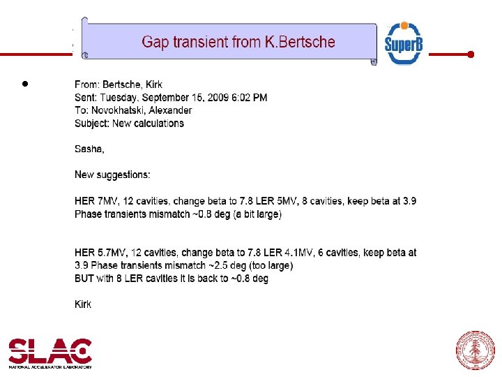
RF Plan: Use PEP-II RF system and cavities • (Novokhatski, Bertsche)

PEP-II RF Cavities match Super-B needs.
 • Novokhatski, Bertsche")
Super-B RF Parameters (Sept 2009) • Novokhatski, Bertsche
 dipole α and g…. on-off @ 50 Hz 2) dipole β")
Injector Layout 1) dipole α and g…. on-off @ 50 Hz 2) dipole β and q…. DC dipoles 4) dipoles l and d …. . Pulsed inverted dipoles @ 50 Hz e- DR A GUN SHB L - 0. 8 Ge. V R α β ≈ 70 m. e+ DR g C B 5. 7 Ge. V 0. 1 Ge. V PS ≈ 320 m. D 0. 8 Ge. V ≈ 60 m. ≈ 400 m. R. Boni θ > 7 Ge. V e+

The IR design • The interaction region design has to accommodate the machine needs as well as the detector requirements – – Final focus elements as close to the IP as possible As small a detector beam pipe as backgrounds allow As thin as possible detector beam pipe Adequate beam-stay-clear for the machine • Low emittance beams helps here – Synchrotron radiation backgrounds under control – Adequate solid angle acceptance for the detector – Twin bore IR quadrupoles

R&D on SC Quadrupoles at the IP Total field in black Coils array Most recent design with BSC envelopes E. Paoloni (Pisa), S. Bettoni (CERN)

Alternative QD 0: Super-ferric • P. Vobly

Inside the detector M. Sullivan

Photons/beam bunch HER M. Sullivan 2. 5 e 6 2. 9 e 7 6. 9 e 5 9. 9 e 6 15680 5. 7 e 5 LER

TDR Topic List • Injection System • Polarized gun • damping rings • spin manipulators • linac • positron converter • beam transfer systems • Collider design • Two rings lattice • Polarization insertion • IR design • beam stay clear • ultra-low emittance tuning • detector solenoid compensation • coupling correction • orbit correction • stability • beam-beam simulations • beam dynamics and instabilities • single beam effects • operation issues • injection scheme • RF System • RF specifications • RF feedbacks • Low level RF • Synchronization and timing • Site • Civil construction • Infrastructures & buildings • Power plants • Fluids plants • Radiation safety • Magnets • Design of missing magnets • Refurbishing existing magnets • Field measurements • QD 0 construction • Power supplies • Injection kickers • Mechanical layout and alignment • Injector • supports • Vacuum system • Arcs pipe • Straights pipe • IR pipe • e-cloud remediation electrodes • bellows • impedance budget simulations • pumping system • Diagnostics • Beam position monitors • Luminosity monitor • Current monitors • Synchrotron light monitor • R&D on diagnostics for low emittance • Feedbacks • Transverse • Longitudinal • Orbit • Luminosity • Electronics & software • Control system • Architecture • Design • Peripherals

Conclusions • Crossing angle collisions work well experimentally at DAFNE. • Parameters for a high luminosity collider seem to hold together. Both Super-B and Super-KEKB now have similar parameters. • Detailed site work and lattice layout computations are advancing. • IR design is coming together • Working on accelerator tolerances now. • Aiming at a White Paper at end of 2009. • Working towards a TDR at end of 2010. • We need more engineering and accelerator design help!
- Slides: 48