Super KEKB Status Report del Super KEKB Commissioning

Super. KEKB Status Report del Super. KEKB Commissioning Workshop, KEK, Nov. 13 th 2013 M. E. Biagini, INFN-LNF

Outlook • • • Super. KEKB Overview Beam dynamics & backgrounds Interaction region Injection system Commissioning plans Conclusions

Workshop Talks • • • • Overview of Super. KEKB, commissioning plan, issues, Y. Funakoshi (KEK) Injector commissioning and issues, M. Satoh (KEK) Photo-cathode RF gun, T. Natsui (KEK) Positron source, T. Kamitani (KEK) Timing synchronization, H. Kaji (KEK) Linac alignment, T. Higo (KEK) LHC Commissioning, F. Zimmermann (CERN) Optics correction @ the LHC, R. Tomas (CERN) CESR TA Overview, D. Rubin (Cornell) Tau-Charm Plans at Tor Vergata, M. Biagini (INFNLNF) BEPC-II beam commissioning, D. Zhou (KEK) PEP-II Beam Commissioning: Some Lessons Learned, M. Sullivan (SLAC) Emittance tuning at CESR-TA, J. Shanks (Cornell) Electron Cloud Induced Beam Dynamics Studies at CESR-TA, K. Sonnad (Cornell) IBS studies at Cesr. TA, M. Ehrlichman (CLASSE) Emittance tuning at ATF II and FACET, G. White (SLAC) • • • Beam optics design for simultaneous injection, T. Miura (KEK) Injection, beam abort, T. Mori (KEK) DR LTR, RTL, M. Kikuchi (KEK) DR beam monitors, H. Ikeda (KEK) DR tuning, Y. Renier (CERN) Ring optics design and correction, H. Sugimoto (KEK) Beam-beam + dynamic aperture, A. Morita (KEK) Beam-beam + lattice nonlinear + space charge, D. Zhou (KEK)) Beam-beam and e-cloud, K. Ohmi (KEK) Beam sizes, J. FLANAGAN (KEK) HOM Effects in PEP-II, A. Novokhatski (SLAC) Vacuum effects in PEP-II, U. Wienands (SLAC) • • • IP feedback, T. Oki (KEK) IR magnet measurements, Y. Arimoto (KEK) Beam collimators, T. Ishibashi (KEK) Background estimation, H. Nakayama (KEK) Background experience at PEP-II, W. Kozanecki (CEA) Overview of Super. B and Tau-Charm Factory Backgrounds and Lifetime, M. Boscolo (INFN-LNF) • • • PEP-II rf system experience, C. Rivetta (SLAC) Bunch-by-bunch feedback, M. Tobiyama (KEK) ) Bunch-by-bunch feedback experience at DAFNE, and DAFNE status report, A. Drago (INFN-LNF) ) Continuous injection experience at PEP-II, U. Wienands (SLAC) ) Collider commissioning strategies, J. Seeman (SLAC) • •

What’s new at Super. KEKB Belle II e+ 4 Ge. V 3. 6 A New IR e- 7 Ge. V 2. 6 A New beam pipe & bellows Colliding bunches New superconducting final focusing quads near the IP Super. KEKB Replace short dipoles with longer ones (LER) Add / modify RF systems for higher beam current Low emittance positrons to inject Redesign the lattices of LER to squeeze the emittance Ti. N-coated beam pipe with antechambers Positron source Damping ring New positron target / capture section Low emittance gun Low emittance electrons to inject Target: L = 8 x 1035/cm 2/s

Machine Design Parameters KEKB parameters Super. KEKB LER HER 3. 5 8 4 7. 007 Beam energy Eb Half crossing angle φ 11 41. 5 # of Bunches N 1584 2500 Horizontal emittance εx 18 24 3. 2 Emittance ratio κ 0. 88 0. 66 Beta functions at IP βx*/βy* Beam currents Ib 1. 64 beam-beam param. ξy Bunch Length Vertical Beam Size sz sx * sy* Luminosity L Horizontal Beam Size units Ge. V mrad x 4 x 1. 4 4. 6 nm /6 0. 27 0. 25 % 32/0. 27 25/0. 30 mm 1. 19 3. 6 2. 6 A 0. 129 0. 090 0. 088 0. 081 6. 0 5. 0 mm 150 10 11 um 0. 048 0. 062 um 1200/5. 9 0. 94 2. 1 x 1034 8 x 1035 cm-2 s-1 /40 /20 x 2 /15 /20

Issues • • IR design and dynamic aperture Low emittance tuning Magnet alignment strategy Beam-beam related issues IP orbit control Beam loss and beam injection Electron clouds Detector beam background
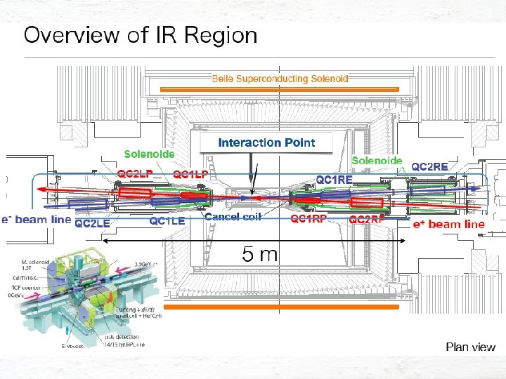

Interaction Region

IR design features

goal: by*=0. 3 mm, ey≈3 pm, ttouschek≥ 600 s local chromatic correction H. Sugimoto

Y. Ohnishi

Corrector coils • Dipole and skew dipole coils make beam-line geometry and correct dispersions • Skew quadrupole coils correct x-y couplings • Sextupole and skew sextupole coils correct error field due to a misalignment of quadrupole coils. This error field affects the dynamic aperture significantly • Octupole coils at QC 1 and QC 2 enlarge the transverse aperture • HER cancel coils correct sextupole, octupole, decapole and dodecapole leakage field from QC 1 P in LER


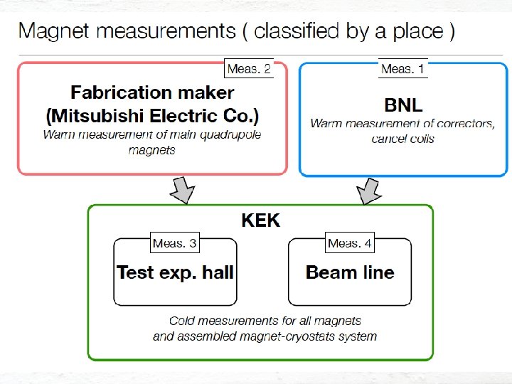
IR magnets measurements • Crowded IR, with 8 quadrupoles, 48 correcting coils, 4 antisolenoids, all superconducting and packed in 10 m • Magnets have to have high precise field with highly stable: – Field harmonics components, – Magnet axis center, – Vibration of magnet and cryostat

IP feedback • The IP orbit control to maintain an optimum beam collision is more difficult than the KEKB case • IP orbit is very sensitive to the vibration of QCS (QC 1, QC 2) magnets • For vertical offset and angle feedback: – Orbital feedback system is under consideration. It was used for KEKB and is based on beam-beam kick calculated from the BPM readouts at both sides of the IP (4 BPMs at 0. 5 m from IP) – Target resolution of BPM is the order of micrometer – Prototype BPM was tested by using sinusoidal input signal and 0. 1 mm resolution has been obtained, successfully • For horizontal offset feedback: – Luminosity dither is being considered as used for PEP-II, because beam-beam kick will not be a sensitive parameter for monitoring collision due to small H beam-beam parameter – Coils in construction at SLAC: designed for the maximum dithering amplitude, which corresponds to 10 % drop of the peak luminosity

Coil mechanical design Design work is under way. Coils will be delivered to KEK by the end of 2013 after field measurement. M. Kosovsky, SLAC
 and orbit change (tracking) : Super. KEKB HER Vertical")
QCSL vertical position oscillation (measurement) and orbit change (tracking) : Super. KEKB HER Vertical orbit at IP (simulation) QCSL vertical position (KEKB measurement) QC 1 L (HER) 200 nm -> ~4 sy* If the QC 1 L magnets of Super. KEKB vibrates with the same amplitude of the QCSL of the KEKB, the orbit change at IP amounts to 4 sy*.
 100 Phase (deg. ) Integral amplitude")
Estimation of QCS vibration and luminosity degradation (vertical) 100 Phase (deg. ) Integral amplitude (nm) 1000 10 Measured ground motion (input data) 1 25 nm@25 Hz H. Yamaoka 0. 1 QC 1 RP and QC 1 RE vibrate with same phase, but the amplitude difference still arises: 25 nm at 25 Hz… Luminosity degradation (based on beam-beam simulation by K. Ohmi) Freq. (Hz) 24. 85 38. 93 69. 34 99. 60 Dy. IP*rms (nm) 18. 63 1. 72 8. 29 3. 14 L/L 0 average (%) 95. 4 99. 8 99. 7 Y. Funakoshi

Countermeasures • Reinforcement of supports for QCS magnets • Rely on the coherency of the oscillation of QC 1 P and QC 1 E (QC 2 P and QC 1 E) • Fast orbit feedback
 Loss wattage = loss")
BG loss distribution Ver. 2013. 6. 12 (6 th campaign) Loss wattage = loss rate * energy of loss particle LER (e+) HER (e-) LER (4 Ge. V e+) Nov. 12 th, 2013 HER (7 Ge. V e-) Rad. Bhabha 0. 63 W (eff. 0. 98 GHz) 0. 88 W (eff. 0. 78 GHz) Touschek 0. 07 W (0. 11 GHz) Coulomb 0. 07 W (0. 10 GHz) 0. 001 W (0. 001 GHz) H. Nakayama (KEK) 1 Ge. V , 1 GHz = 0. 16 W 0. 02 W (0. 02 GHz) 21

Where we should put vertical collimator? Collimator aperture should be narrower than QC 1 aperture. Collimator position d[mm] TMC: Aperture TMC instability should be avoided. beta[m] Assuming following two formulae: > 1. 44 m. A/bunch (LER) taken from “Handbook of accelerator physics and engineering, p. 121” Kick factor (in case of rectangular collimator window) We should put collimator where beta_y is SMALL! Nov. 12 th, 2013 H. Nakayama (KEK) 22
 tungsten (20~70 mm t) tungsten")
Tungsten shields inside QCS cryostat tungsten (10 mm t) tungsten (20~70 mm t) tungsten (50 mm t) QC 2 RE e- QC 1 RE QC 1 RP QC 2 RP e+ tungsten(~30 mm t) tungsten (10 mm t) e+ e- Major beam loss position and shower development direction Nov. 12 th, 2013 H. Nakayama (KEK) 23
 KEKB (operation) Super. KEKB LER HER Radiative Bhabha 21. 3")
Beam lifetime KEKB (design) KEKB (operation) Super. KEKB LER HER Radiative Bhabha 21. 3 h 9. 0 h 6. 6 h 4. 5 h 28 min. 20 min. Beam-gas 45 ha) 24. 5 min. b) 46 min. b) Touschek 10 h - 10 min. Total 5. 9 h 7. 4 h ~133 min. ~200 min. 6 min. Beam current 2. 6 A 1. 1 A 1. 6 A 1. 1 A 3. 6 A 2. 6 A 0. 12 m. A/s 0. 04 m. A/s 0. 23 m. A/s 0. 11 m. A/s Loss Rate 10 m. A/s 7. 2 m. A/s 4 n. C@25 Hz 2. 9 n. C@25 Hz a) Bremsstrahlung b) Coulomb scattering, sensitive to collimator setting As for loss rate, beam loss accompanied with the beam injection should be added.

Magnet alignment strategy • The target positions of the initial alignment of Super. KEKB is a smoothed curve made from present (2013 )magnet positions (not on a plane). • The tolerance of magnets alignment around the target curve is the same as KEKB. – Position error: 100 mm (1 s) – Rotational error: 100 mrad (1 s) • We have to rethink about this? • We will need special care for the alignment of the magnets around the local chromaticity correction.
 Super. KEKB HER A. Morita")
Effects of Tunnel deformation at Target (7. 8 pm) Super. KEKB HER A. Morita Vertical emittance -If the alignment error around the V-LCC (vertical local chromaticity correction) area Tunnel deformation observed at KEKB is excluded, the vertical emittance can be - A large subsidence has been observed: preserved well below the target value with ~ 2 mm/year and still in progress. optics corrections. - In the construction period of KEKB (1998), - As for the alignment error of V-LCC, we all magnets were aligned on the same plane. will need a special care. This is a remaining problem.

Simulation for Super. KEKB with machine errors • Simulation was done by H. Sugimoto in case of HER. • Assumed machine errors sx = sy [mm] sq [mrad] DK/K Normal Quad 100 2. 5 x 10 -4 Sextup 100 2. 5 x 10 -4 0 100 0 0 0 10 x 103 2 mm (resolution) Bend QC 1, QC 2 BPM Machine errors are created randomly with gaussian distributions. • Corrections – Closed orbit, x-y coupling, beta-beat, dispersions (KEKB methods) • SVD threshold = 10 -2

vertical emittance w errors & correction OK! H. Sugimoto

lifetime ideal lattice lifetime w. errors & correction H. Sugimoto OK!? off-momentum optics not recovered

Dynamic aperture with different types of errors No errors Rotation errors of quadruples seems most dangerous. Each sextuple has a skew quadrupole corrector coil. We may have to rethink tolerance of rotation errors of normal quadrupoles. H. Sugimoto

Beam-beam related issues • Beam lifetime shortening with beam-beam effects • Luminosity degradation – The design luminosity was determined based on the strong-strong beam-beam simulation – Beam-beam + lattice nonlinearity and space charge effect

Beam-beam effect on Touschek lifetime A. Morita in LER t≈300 s with beam-beam
![Super. KEKB beam-beam simulation Super. KEKB design LER HER ex [nm] 3. 2 4.](http://slidetodoc.com/presentation_image_h2/42bc92027ed6566924e9b9a7f73cdda9/image-33.jpg "Super. KEKB beam-beam simulation Super. KEKB design LER HER ex [nm] 3. 2 4.")
Super. KEKB beam-beam simulation Super. KEKB design LER HER ex [nm] 3. 2 4. 6 ey [pm] 8. 64 11. 5 k [%] 0. 27 0. 25 Super. KEKB design luminosity Strong-strong method (PIC) For the long-rage force, the gaussian distribution was assumed. K. Ohmi Smaller (single beam ) vertical emittance gives higher luminosity. Much lower vertical emittance than the design (about half) will be needed to achieve the design luminosity.

lattice-dependent effects reduce predicted luminosity by 10 -30% D. Zhou

space charge reduces predicted luminosity by another 20% strong lattice effect already at low current D. Zhou further degradation from space charge

Ideal crab waist recovers dynamic aperture A. Morita

Realistic crab waist has less positive effect A. Morita

Main obstacle: non-linear Maxwellian fringe of FF quadrupoles

Conclusions on DA & CW study • Beam-beam effect reduces dynamic aperture & Touschek lifetime • DA degradation by BB effect COULD be cured by crab waist if I-cell of CW was linear • Intrinsic non-linearity (Maxwellian fringe) blocks dynamic aperture of CW on our lattice • Achieving 40σ aperture by using octupole correctors is difficult without QCs allowed multipole suppression • Tuning K 5 corrector on real machine WOULD be difficult because of fragmentation of good parameter region

Electron cloud issues Y. Suetsugu • The single bunch instability is main concern. – Leads to increase in emittance – Coupled bunch instabilities will be cured by feedback system. • Simulation and calculation by Ohmi, et al. Here, Threshold of density E [Ge. V] = 4. 0 = 7828 g = 0. 026 ns sz [m] = 6. E-03 c [m/s] K Q re [m] b y [m] L [m] K. Ohmi , KEK Preprint 2005 -100 (2006) = 3. E+08 = 11 =7 = 2. 80 E-15 = 25 = 3016 Nb Qb[C] Sb [m] l [C/m] s y [m] s x [m] = 6. 25 E+10 = 1. 4 E-08 = 1. 2 = 5. 2 E+12 = 2. E-05 = 2. E-04 (1. 4 m. A/bunch) (4 ns) (Qb/2/sz) we = 5. 46 E+11 K = we sz/c = 10. 9 Q = Min(Qnl, we sz/c) ρth [e-/m 3] =1. 59 E 11 Qnl ~7 Target: 1 E 11 40

Latest simulation result on the threshold value of instability • Simulation with PEHTS 2 by D. Zhou and K. Ohmi – With uniform beta functions and uniform electron cloud density along the ring, the threshold for electron cloud density is about 5. 0 x 1011 m-3. – With realistic beta functions and uniform electron cloud density along the ring, the threshold reduces to about 1. 6 x 10¹¹ m-3. – With realistic beta functions and estimated sdependent electron cloud density along the ring, the threshold is about 5. 0 x 1011 m-3.
")
Expected electron density Y. Suetsugu • ne after applying countermeasures: estimated from experiments (Red) • Compared with results of CLOUDLAND (Blue) – dmax=1. 2, Solenoid field=50 G ( ne=0), Antechamber; photoelectron yield =0. 01 (1/10) • ne of approx. 1/5 of the target value is expected. Condition ne [m-3] Circular Cu chamber [KEKB beam pipe] 5. 2 E 12 +Solenoid at Drift (1/50) 4. 7 E 11 +Antechamber (1/5)+Ti. N (3/5) 5. 7 e 10 +Electrode in Wiggler (1/100) 3. 5 e 10 +Groove in Bend (1/4) 2. 0 E 10 Target value for ne: ~1 x 10¹¹ KEKB~3 x 10¹¹ If the latest simulation result on the threshold is true, there is a margin of a factor 25! 42
 to be installed in LER in")
Beam collimators New collimators (10 H, 3 V) to be installed in LER in Phase II, 2 H installed in Phase I Old collimators kept in HER in Phase I, planned renewal in Phase II New collimator H has part of the movable heads placed in the antechambers New V collimator is similar, with the inside of the antechambers tapered to avoid trapped mode • Part of the movable heads is hidden inside the antechambers to reduce the impedance and increase maintainability by downsizing the collimators • •

HOM absorbers • In Phase-I stage, no plan to install HOM absorbers because the loss factor is quite small (< 0. 1 V/p. C/collimator) • However, design of HOM absorbers is continuing (several materials tested for fingers and walls)
![Super. KEKB requirements (tentative) Charge [n. C] Normalized emittance[mm] KEKB (e+/e-) Super. KEKB (e+/e-)](http://slidetodoc.com/presentation_image_h2/42bc92027ed6566924e9b9a7f73cdda9/image-45.jpg "Super. KEKB requirements (tentative) Charge [n. C] Normalized emittance[mm] KEKB (e+/e-) Super. KEKB (e+/e-)")
Super. KEKB requirements (tentative) Charge [n. C] Normalized emittance[mm] KEKB (e+/e-) Super. KEKB (e+/e-) 1/1 4/5 2100/300 100/50 (H) 20/20 (V)

Photo-cathode RF gun • High current : 5 n. C for e⁻ (~ >10 n. C for e⁺) • Low emittance : ~ < 10 μm. rad • Combination of unique technologies – Laser system with Yb fiber oscillator, fiber amplifier, regenerative amplifier, multi-pass amplifier, pulse picker, frequency converter – Quasi traveling-wave side coupled cavity – Ir 5 Ce photo cathode • • 46 Already obtained 3. 5 ~ 5 n. C Commissioning started Temporal manipulation for lower energy spread Cavity and cathode are mostly ready, laser system under improvement for higher charge

Positron Source • High current positron is required • Positron capturing with flux concentrator (FC) and large aperture S-band structure (LAS) • Deceleration field to reduce satellite bunches • Pinhole beside target for electron beam • Protection system with beam spoilers 47

e+/e- beam switching at target bridge coils side view 10 n. C primary e- DC QM spoiler target solenoid LAS Accel. structure target diameter 4. 0 mm rear view target offset 3. 5 mm e+ beam hole 5 n. C injection e. Flux Concentrator pulse ST pulse QM 2. 0 mm FC offset hole diameter 2. 0 mm 7. 0 mm FC aperture Two possible schemes of beam switching by orbit bump 1) e+ on-axis, e- offset e- emittance growth by solenoid kick induced orbit 2) e- on-axis, e+ offset we take this scheme. e+ yield degradation (50% 10%) ICFA Mini-Workshop on Commissioning of Super. KEKB & e+/e- colliders (2013. 11) 48

Dynamic Aperture with beam-beam LER : w/ damping Injection efficiency: ~ 84% w/o machine errors Linac beam: gex ~117 mm , gey ~2. 5 mm Dx / sx DE / se sler_1686 sx@Injection = 0. 55 mm -> 12 sx ~ 6. 6 mm

Beam injection issues • Dynamic aperture with beam-beam effect in LER – Estimated injection efficiency with beam-beam • ~84% w/o machine errors • Requirements to Linac beam (emittance etc. ) will be considered after we finish the investigation on dynamic aperture with beam effects. • HER injection – Transverse ring acceptance is marginal with the design optics to keep enough injection efficiency – Maybe, we will need to switch to the “synchrotron injection” in the process of squeezing beta functions at IP • Synchronization issue between Linac and Super. KEKB rings – Introduce damping ring

Injector Commissioning Plan and Issues Summary • Injector commissioning started. • New Photo-cathode RF gun has successfully manufactured and installed. – 3 n. C from New RF Gun – 0. 05 n. C, 5 Ge. V at end of Linac • First stage of commissioning: – Gun commissioning (laser and cavity conditioning) – High intensity charge – Emittance preservation w/ low charge at Sector A, B 51

Super. KEKB Longitudinal FB plan Install LFB in LER only. HER is optional. Considering to use 4 DAFNE type kicker, with 2 -input, 2 -output ports for larger capture range.

Feedback kicker • Transverse kicker – We will use similar transverse stripline kicker, at least, at the early stage of the commissioning. • want to continue collaborate with SLAC for much larger power tolerant structure. • Longitudinal kicker – Designed 2 -in, 2 -out DAFNE-type kicker with shunt impedance of around 1. 6 k. W (Q seems a little bit higher, though) – Will fabricate two-sets within this fiscal year
 • Machine condition – Super.")
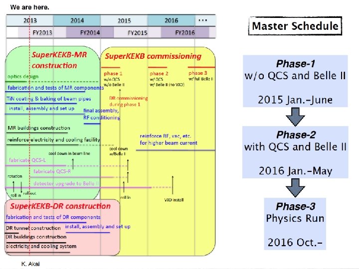
Commissioning phase 0 (2013 Sep. ~ 2014 Dec. ) • Machine condition – Super. KEKB rings: construction – Linac commissioning in parallel with its construction • Summer shutdown (2013) – – – Linac Alignment Remove e+ source and capture section New Chicane in A 1 unit Install and Relocate many magnets and monitors Modify many parts of control software • Linac e- beam – Commissioning of new photocathode RF gun • Cavity conditioning • Laser tuning – Low emittance 5 n. C – 10 n. C (for e+ production primary electron)
 • Machine condition – No QCS, No")
Commissioning phase 1 (2015 Jan. ~ June) • Machine condition – No QCS, No solenoid (no Belle II), No beam collision • Tuning items – Linac tuning (if necessary) – Basic commissioning of machine (~ 1. 5 month) • Injection tuning, Hardware check and bug fix, software bug fix – Vacuum scrubbing (>~3 months) • Belle II people request enough vacuum scrubbing in this stage (before Belle II roll-in). At least one month with beam currents of 0. 5 ~ 1 A. – Damping ring commissioning (start from May 2015) • Beam injection with damping ring – Detector beam background • Study with Beast detectors, check of collimator system (two new-type collimators in LER) – Some optics tuning • With day-1 optics • Low emittance tuning w/o Belle-II solenoid – Study of beam instability (FII, e-cloud) • Tuning on bunch-by-bunch feedback
 Feb. ~ June Machine condition")
• Commissioning phase 2 (2016 Jan. ~ May) Feb. ~ June Machine condition – w/ QCS, w/ Belle II (w/o VXD), TOP detectors partially installed, full accelerator tuning, no physics experiment • Tuning items – Optics tuning • • Tentative target values of IP beta’s: βx*: x 4, βy*: x 8 Optics tuning with QCS and Belle II solenoid Low emittance tuning w/ Belle II solenoid Optics tuning w/ beam collision – Detector beam background • Study with Belle II detector, test of continuous injection – Increase of beam currents (instability, RF power, vacuum issues) • Detector background may possibly give some restrictions • Continue upgrade for RF system (support ~70% of design beam currents) – Beam collision tuning • Orbit feedback (fast feedback, dithering system) • Collision tuning w/ “Nano-Beam” scheme – Luminosity tuning • Tuning knobs (x-y coupling at IP etc. ) • Target luminosity: 1 x 1034 cm-2 s-1 (design of KEKB)
 • Machine condition – Full set of")
Commissioning phase 3 (2016 Oct. ~ ) • Machine condition – Full set of Belle II, Physics experiment will start • Maybe some TOP counters will be delayed • Tuning items – Optics tuning • Toward design values of IP beta’s – Maybe it will take several years • Low emittance tuning: – Design values for vertical emittances are very small. Demonstration of feasibility of TLEP • Optics tuning w/ beam-beam effect – Detector beam background • Establishment of continuous injection (azimuthal VETO) – Increase of beam currents • Design values are as twice high as those of KEKB – Luminosity tuning • Study on effects of lattice non-linearity and space-charge • Stability of tuning will be an important issue (continuous optics correction? )
 Super. KEKB luminosity projection Goal of Belle II/Super. KEKB Peak luminosity")
Integrated luminosity (ab-1) Super. KEKB luminosity projection Goal of Belle II/Super. KEKB Peak luminosity (cm-2 s-1) 9 months/year 20 days/month Commissioning starts in early 2015. Shutdown for upgrade Calendar Year
 • Budget 410 M$ – Total construction budget is 314 Oku-Yen")
Overall budget (original) • Budget 410 M$ – Total construction budget is 314 Oku-Yen for Rings, Injector, and Belle-II – Most of the budget comes year-by-year based – Operation budget is expected in FY 2014 and later JFY 2010 JFY 2011 JFY 2012 JFY 2013 JFY 2014 Very Advanced Research SP (100 Oku-Yen) JFY 2015 JFY 2016 Super. KEKB commissioning Other budgets for construction (214 Oku-Yen) Unit: Oku-Yen (~1. 1 M$) JFY 2010 VARSP Operation budget (continues - - - ) We are here JFY 2011 JFY 2012 JFY 2013 JFY 2014 Total 75. 0 10. 5 14. 5 0 0 100. 0 Others 0 41. 6 40. 2 61. 6 46. 7 190. 0 Buildings 0 4. 5 12. 4 7. 2 0 24. 1 75. 0 56. 6 67. 1 68. 8 46. 7 314. 1 Supplied Total Status 60

Conclusioni • La costruzione di Super. KEB sembra essere a buon punto, anche se la strategia di commissioning in 3 fasi probabilmente dilatera’ i tempi • Ci sono criticita’ soprattutto negli anelli (IR, apertura dinamica, crab waist, beam-beam, iniezione nei rings, tolleranze agli errori, emittance tuning) che ancora necessitano studi e soluzioni • Un grande sforzo con un budget adeguato e risorse umane in qualche settore limitate
- Slides: 61