
SUMMARY CHAPTER 6 TRANSFORMER BAKISS HIYANA ABU BAKAR
SUMMARY CHAPTER 6: TRANSFORMER BAKISS HIYANA ABU BAKAR 1
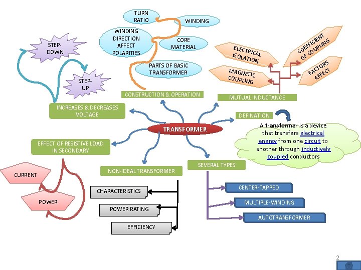
TURN RATIO WINDING DIRECTION AFFECT POLARITIES STEPDOWN WINDING CORE MATERIAL ELECT R ISOLA ICAL TION PARTS OF BASIC TRANSFORMER STEPUP MAGN ETI COUPL C ING CONSTRUCTION & OPERATION MUTUAL INDUCTANCE INCREASES & DECREASES VOLTAGE DEFINATION TRANSFORMER EFFECT OF RESISTIVE LOAD IN SECONDARY NON-IDEAL TRANSFORMER CURRENT CHARACTERISTICS POWER NT E I G FIC LIN F P E CO COU OF S OR T C T FA FEC F A POWER RATING A transformer is a device that transfers electrical energy from one circuit to another through inductively coupled conductors SEVERAL TYPES CENTER-TAPPED MULTIPLE-WINDING AUTOTRANSFORMER EFFICIENCY 2
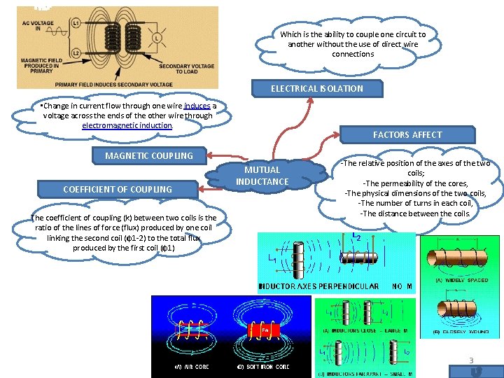
Which is the ability to couple one circuit to another without the use of direct wire connections ELECTRICAL ISOLATION • Change in current flow through one wire induces a voltage across the ends of the other wire through electromagnetic induction. FACTORS AFFECT MAGNETIC COUPLING COEFFICIENT OF COUPLING The coefficient of coupling (k) between two coils is the ratio of the lines of force (flux) produced by one coil linking the second coil (φ1 -2) to the total flux produced by the first coil (φ1) MUTUAL INDUCTANCE -The relative position of the axes of the two coils; -The permeability of the cores, -The physical dimensions of the two coils, -The number of turns in each coil, -The distance between the coils. 3
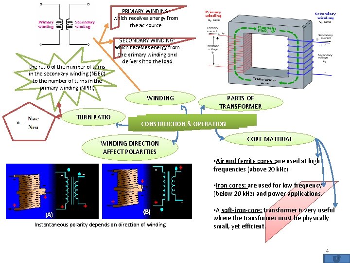
PRIMARY WINDING: which receives energy from the ac source the ratio of the number of turns in the secondary winding (NSEC) to the number of turns in the primary winding (NPRI) SECONDARY WINDING: which receives energy from the primary winding and delivers it to the load WINDING TURN RATIO PARTS OF TRANSFORMER CONSTRUCTION & OPERATION WINDING DIRECTION AFFECT POLARITIES CORE MATERIAL • Air and ferrite cores : are used at high frequencies (above 20 k. Hz). • Iron cores: are used for low frequency (below 20 k. Hz) and power applications. Instantaneous polarity depends on direction of winding. • A soft-iron-core: transformer is very useful where the transformer must be physically small, yet efficient. 4
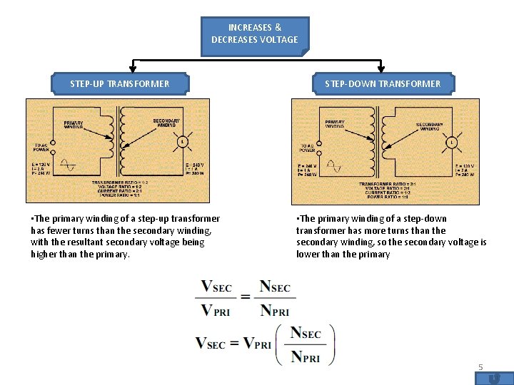
INCREASES & DECREASES VOLTAGE STEP-UP TRANSFORMER • The primary winding of a step-up transformer has fewer turns than the secondary winding, with the resultant secondary voltage being higher than the primary. STEP-DOWN TRANSFORMER • The primary winding of a step-down transformer has more turns than the secondary winding, so the secondary voltage is lower than the primary 5
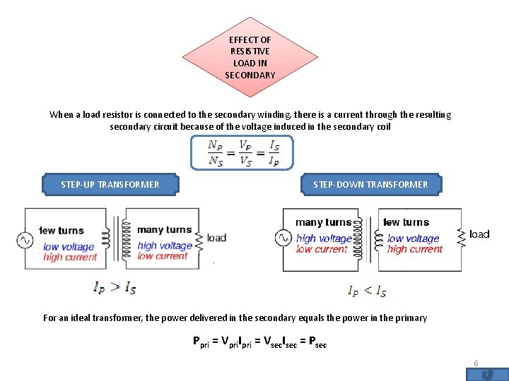
EFFECT OF RESISTIVE LOAD IN SECONDARY When a load resistor is connected to the secondary winding, there is a current through the resulting secondary circuit because of the voltage induced in the secondary coil STEP-UP TRANSFORMER STEP-DOWN TRANSFORMER For an ideal transformer, the power delivered in the secondary equals the power in the primary Ppri = Vpri. Ipri = Vsec. Isec = Psec 6
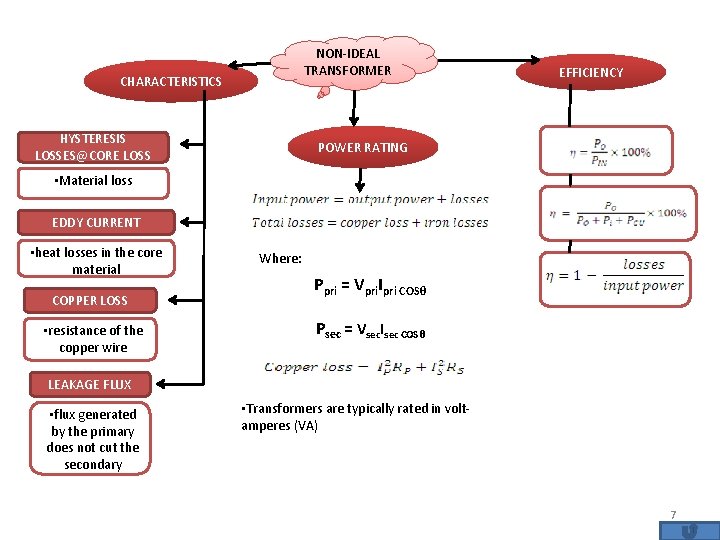
NON-IDEAL TRANSFORMER CHARACTERISTICS HYSTERESIS LOSSES@CORE LOSS EFFICIENCY POWER RATING • Material loss EDDY CURRENT • heat losses in the core material COPPER LOSS • resistance of the copper wire Where: Ppri = Vpri. Ipri COSθ Psec = Vsec. Isec COSθ LEAKAGE FLUX • flux generated by the primary does not cut the secondary • Transformers are typically rated in voltamperes (VA) 7
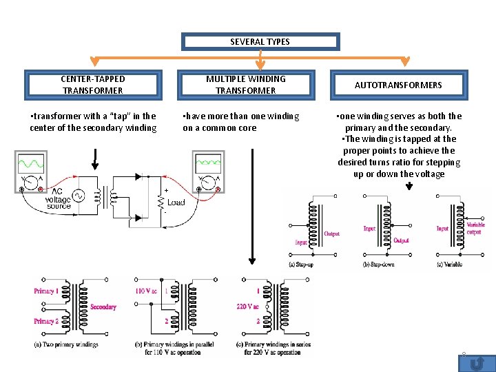
SEVERAL TYPES CENTER-TAPPED TRANSFORMER • transformer with a “tap” in the center of the secondary winding MULTIPLE WINDING TRANSFORMER • have more than one winding on a common core AUTOTRANSFORMERS • one winding serves as both the primary and the secondary. • The winding is tapped at the proper points to achieve the desired turns ratio for stepping up or down the voltage 8
- Slides: 8