Sucker Rod Pump Basics Presentation Contents Sucker Rod

Sucker Rod Pump Basics

Presentation Contents: ØSucker Rod Pumps The Five Basic Components of a Pump Ø Operation of a Sucker Rod Pump Ø Types of Sucker Rod Pumps Ø Material Selection of Pump Components Ø ØObservations at the Bleeder Valve ØHandling a Sucker Rod Pump

The Five Basic Components of a Sucker Rod Pump: Barrel Tube Ø Plunger Ø Traveling Valve Ø Standing Valve Ø Seating Assembly Ø

Basic Components of the Sucker Rod Pump PLUNGER TRAVELING VALVE BARREL TUBE STANDING VALVE HOLD DOWN

The Five Basic Components of a Sucker Rod Pump: Barrel Tubes Thin Wall RW & RS Barrel Heavy Wall RH Barrel Tubing Pump TP Barrel

The Five Basic Components of a Sucker Rod Pump: Plungers Pin End Spraymetal Plunger Box End Spraymetal Grooved Plunger Monel Pin Spraymetal Plunger Pressure Actuated Plunger

The Five Basic Components of a Sucker Rod Pump: Rings for Soft-Packed Plungers Composition Ring Split Composition Ring Flexite Ring Pressure Actuated Ring Valve Cup

The Five Basic Components of a Sucker Rod Pump: Traveling Valves Closed-Type Cage for Pin-End Plunger Open-Type Cage for Travel Barrel Insert Style Pump Closed-Type Cage for Pin-End Plunger Closed-Type Cage for Box-End Plunger

The Five Basic Components of a Sucker Rod Pump: Standing Valves Closed-Type Cage Insert Style Closed-Type Cage Open Cage Traveling Barrel Type Open Cage Tubing Pump Closed Cage Tubing Pump

The Five Basic Components of a Sucker Rod Pump: Valves for Traveling & Standing Ball & Seat Flat Type Ball & Seat Rib Type

The Five Basic Components of a Sucker Rod Pump: Seating Assemblies 3 Cup API Bottom Hold Down 3 Cup API Top Hold Down 3 Cup Type O Bottom Hold Down Mechanical Bottom Lock API Type Mechanical Top Lock API Type

The Five Basic Components of a Sucker Rod Pump: Seat / Unseat Requirements

The Basic Operation of a Sucker Rod Pump A sucker rod pump is no more than a cylinder, or tube, consisting of two sections or chambers. One section is stationary or secured to the tubing. The other section travels with the sucker rod string. There are usually two valves working with these sections taking turns opening and closing. The valves transfer fluid from the bottom chamber to the top chamber and ultimately into the tubing and up to the wellhead.

Arrows Show Fluid Travel on the Upstroke SUCKER ROD TUBING TRAVELING UNIT STANDING UNIT

Arrows Show Fluid Travel on the Downstroke SUCKER ROD TUBING TRAVELING UNIT STANDING UNIT

Pressures in the Wellbore

API Bottomhole Pump Designation

Types of Sucker Rod Pumps Insert Type Pumps Installed on the end of a sucker rod string as a complete unit. Ø Can be ran deeper than Tubing Pump. Ø Special service applications are available for most types. Ø Less service cost than a tubing pump. Ø

Types of Sucker Rod Pumps Types of Insert Type Pumps Bottom Hold Down: Ø RWTC Ø RWBC Ø RHBC Top Hold Down: Ø RWAC Ø RHAC

RWTC – API Insert Pump ØBarrel Travels with Rod String. ØBottom Holddown. ØThin Wall Barrel.

RWTC – API Insert Pump Advantages of RWTC Pumps: Ø Disadvantages of RWTC Pumps: Recommended for sandy wells. Ø Ø Recommended for intermittent pumping wells. Ø Ø Not recommended for gassy wells. Not recommended for wells with low fluid levels. Not recommended for deep wells.

RWAC – API Insert Pump ØPlunger Travels with Rod String. ØTop Holddown. ØThin Wall Barrel. ØBarrel Extends Below Seating Nipple.

RWAC – API Insert Pump Advantages of RWAC Pumps: Ø Recommended for sandy wells. Disadvantages of RWAC Pumps: Ø Ø Recommended for low fluid level, gassy, or foamy wells. Ø Ø Recommended for wells requiring long pumps. Ø Ø Not recommended for deep wells. Valve rod is the weak link. Not recommended for intermittent pumping. Tubing erosion opposite top guide.

RWBC – API Insert Pump ØPlunger Travels with Rod String. ØBottom Holddown. ØThin Wall Barrel.

RWBC – API Insert Pump Advantages of RWBC Pumps: Ø Ø Recommended for deep wells. Recommended for low fluid levels. Disadvantages of RWBC Pumps: Ø Ø Ø Not recommended for sandy wells. Valve rod is the weak link. Not recommended for intermittent pumping. Tubing erosion opposite top guide. Barrel subject to corrosive attack.

RHBC – API Insert Pump ØPlunger Travels with Rod String. ØBottom Holddown. ØHeavywall Barrel.

RHBC – API Insert Pump Advantages of RHBC Pumps: Ø Ø Recommended for deep wells. Recommended for low fluid levels. Disadvantages of RWBC Pumps: Ø Ø Recommended for stroke through design to combat scale and/or gyp. Ø Ø Not recommended for sandy wells. Valve rod is the weak link. Not recommended for intermittent pumping in sandy wells. Tubing erosion opposite top guide. Barrel subject to corrosive attack.

RHAC – API Insert Pump ØPlunger Travels with Rod String. ØTop Holddown. ØHeavy Wall Barrel ØBarrel Extends Below Seating Nipple.

RHAC – API Insert Pump Advantages of RHAC Pumps: Ø Recommended for sandy wells. Disadvantages of RWBC Pumps: Ø Ø Recommended for low fluid levels, gassy, or foamy wells. Ø Ø Ø Recommended for stroke through design to combat scale and/or gyp. Recommended for wells requiring long pumps. Ø Ø Not recommended for deep wells. Valve rod is the weak link. Not recommended for intermittent pumping. Tubing erosion opposite top guide.

Hollow Tube ØPlunger Travels with Rod String. ØBottom Hold Down. ØAvailable in Thin & Heavy Wall. ØAvailable in Bottom & Top Hold Down. ØValve Rod is Replaced with Pull Tube. ØValve can be added on top of tube.

Hollow Tube Advantages of Hollow Tube Pumps: Ø Ø Recommended for deep wells. Pump discharge is spread across pump stroke (helps reduce tubing erosion). Two Stage effect with valve on top of tube. Pull Tube is more rigid than typical valve rod. Disadvantages of Hollow Tube Pumps: Ø Ø Not recommended for sandy wells. Barrel subject to corrosive attack.

Sand Pump ØCan be built as Stationary or Travel Barrel type pump. ØBottom Hold Down. ØHeavy Wall Barrel construction. ØValve Rod is Replaced with Plunger. ØCheck Valve on top of pump.

Sand Pump Advantages of San’ Pumps: Ø Ø Ø Recommended for wells producing sand. Recommended for low fluid levels. Disadvantages of San’ Pumps: Ø Ø Not recommended for pumping gassy wells. Plunger replaces pull rod. Ø Ø Stationary barrel design can sand in with extensive run times. Fluid discharged length of pump stroke. Barrel subject to corrosive attack unless upgraded material is used.

Volumax Ø Multiple volume type pump. Ø Obtains higher production than tubing pumps. Ø Increases loads on sucker rod strings

Volumax Advantages of Volumax Pumps: Ø Ø Produces large volumes of fluid. Produces same volume as tubing pump with reduced cycle rate. Disadvantages of Volumax Pumps: Ø Ø Insert type pump, can be pulled with rod string. Initial cost of pump is higher than regular pump Not recommended for pumping sandy wells. High unseating force on pump requires special hold down.

Three Tube ØOuter and Inner Barrel Tubes travel with rod string. ØStanding Barrel (Middle Barrel Tube) is stationary. ØNo plunger incorporated in pump. ØCheck valve on top of pump. ØRequires faster Strokes per Minute than conventional pumps due to

Three Tube Advantages of Triax Pumps: Ø Ø Recommended for sandy wells. Traveling barrel usually keeps sand off hold down assembly. Top valve acts as check valve to keep sand out of pump. Insert type pump, can be pulled with rod string. Disadvantages of Triax Pumps: Ø Ø Ø Not recommended for gassy applications. Not recommended for low fluid level wells. Has depth limitations.

Circle-A-Pump Ø Non API pump design. Ø Designed for maximum flow Ø Designed for minimum turbulence. Ø Designed for maximum efficiency. Ø Can be built up to and including 3. 50” bore size.

Circle-A-Pump Advantages of Circle-APumps: Ø Ø Recommended for sandy wells. Recommended for low fluid level, gassy, or foamy wells. Recommended for wells requiring long pumps. Recommended for deep well applications. Disadvantages of Circle -A-Pumps: Ø Ø Ø Valve rod is the weak link in the rod string. Initial cost is higher than conventional pump. Material selection is limited.

Tension Pump Ø Keeps the rod string in tension on the downstroke. Ø Raises the minimum load of the sucker rod string. Ø Can be configured as either a rod pump or a tubing pump. Ø Increase in bottomhole stroke. Ø Good application for both steel and fiberglass sucker rod strings.

Tension Pump Advantages of Tension Pumps: Disadvantages of Tension Pumps: Ø Increase in Minimum Sucker Rod Loads. Ø Increase in Maximum Allowable Sucker Rod Stress. Ø Reduction/Elimination of Compressive Loads. Ø Increase in Net Plunger Travel. Ø Decrease in Polish Rod Horsepower. Ø May not be good in gassy applications. Ø Reduced Pump Efficiency. Ø Unsure a POC will determine a pumped off condition. Ø Lack of existing software to monitor loading. Ø Higher pump cost than standard pump.

The “Gas Bailer” Pump

Types of Sucker Rod Pumps Tubing Pumps Typically produces more fluid than a rod pump. Ø More costly to service than a rod pump. Ø Application is in shallow to medium depth wells due to loading on rod string and pumping unit. Ø Not a good choice in gassy wells. Ø

THBC – API Tubing Pump ØPlunger Travels with Rod String. ØBarrel Ran on Bottom of Tubing String. ØPlunger Ran on Bottom of Rod String. ØBottom Holddown. ØHeavy Wall Barrel.

Accessories Available for Subsurface Pumps Top Bottom Check Discharge Valve Top Tubing Seal Drain Assembly

Selecting a Subsurface Pump What Information is Required? Ø Casing & Tubing Size Ø Equipment Available (Unit, Rods, etc. ) Ø Depth Ø Fluid ü Production Required ü Viscosity ü Abrasion ü Corrosion

How do These Conditions Affect the Selection Process? Ø Tubing / Casing Size: Ø Pump Bore Size. Ø Equipment Available: Ø Pumping Unit & Rod Design Dictate Pump Size (Bore & Length). Ø Depth: Ø Type of Barrel That Can be Run. Ø Holddown Position. Ø Fluid: Ø Ø Ø Size Pump Required to Reach Production Target. Pump Fit Required. Material Selection. Hold Down Position. Type of Accessories Available.

Determining Pump Length Example: 3, 000’ Well, Steel Sucker Rods, 120” Surface Stroke

RW Barrel Selection Steel Barrel Yield Strength = 60, 000 PSI Brass Barrel Yield Strength = 60, 000 PSI

RH & TH Barrel Selection Steel Barrel Yield Strength = 60, 000 PSI Brass Barrel Yield Strength = 60, 000 PSI

Barrel Tube Selection

Plunger Selection

Plunger Fit & Length Selection The following recommendations are based upon years of experience in manufacturing and installation of subsurface pumps. They are to be used as a guide in design of subsurface pumps. Individual well conditions such as API gravity, Sand content, etc. must be considered in final plunger fit. Maximum Plunger Fit Size 1. 06" & 1. 25" 1. 50" 1. 75" & 2. 00" Fit -0. 001" -0. 002" -0. 003" Plunger Length 2 ft. Size 2. 25 & 2. 50" 2. 75" & 3. 75" 4. 75" & 5. 75" Fit -0. 004" -0. 005" -0. 007" Reduce fit (increase clearance) by -0. 001" for each additional foot of length up to 4 ft. Example: 2. 25" x 3 ft. = -0. 004" plus -0. 01" = -0. 005" fit or 2. 25" x 4 ft. = -0. 004" plus -0. 002" = -0. 006 fit Maximum Plunger Length Size 1. 06" 1. 25" 1. 50" 1. 75" 2. 00" 2. 25" 2. 50" 2. 75" 3. 75" 4. 75" 5. 75" 2, 000' 2' 2' 2' 3, 000' 2' 2' 2' ----- Well Producing Depth 4, 000' 5, 000' 3' 3' 3' 2' 3' 2' 2' 2' ------- 6, 000' 4' 4' 3' 3' ------- 7, 000' 4' 4' 4' 3' --------- 8, 000' 5' 5' 5' 4' 4' 4' ----------- Plunger Length 2 ft.

Ball & Seat Selection

"A" "B" "C" "X" 30 EA 70 - T SS H N R O 17 -4 A A C C B B A A B B B A A A X X C C X B A A A B B C C A A B A C A A A A A M 30 00 A A C C B B X X C C B B C A 86 20 VA N L B EL R B A LE 40 5 LE O U D A SE LL R O IE Y S ST ST A EE L IN L EE ST N O B R A C 10 45 None A None + Abrasion X Severe H 2 S + Abrasion X Mild H 2 S B Mild H 2 S + Abrasion X Severe CO 2 + Abrasion X Mild CO 2 C Mild CO 2 + Abrasion C Severe H 2 S + CO 2 X Severe H 2 S + CO 2 + Abrasion X Mild H 2 S + CO 2 C Mild H 2 S + CO 2 + Abrasion C Severe Brine X Mild Brine + Abrasion C Oxygen X TR SS EA TE D SS Fitting Selection Material suitable under most conditions. Corrosion or erosion expected, but material may be suitable under some conditions. Corrosion or erosion usually too severe for successful use. Material not suitable for use.

Spacing a Pump at the Wellsite

How Important is Spacing ?

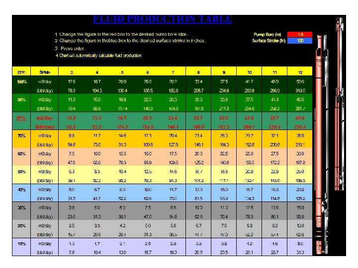
Efficiencies of Sucker Rod Pumps Theoretical Production: Pump Constant x SPM x Surface Stroke Length Actual Production: Pump Constant x SPM x Net Plunger Stroke Factors Causing Efficiency Losses Rod Design: Stretch & Overtravel Tubing: Anchored or Unanchored Fluid Slippage: Viscosity, Pump Clearances, Pump Wear Gas Interference: GOR & GLR

Pump Production Formula Net Plunger Travel x SPM x Pump Constant

Observations at the Bleeder for Sucker Rod Pumps

Observations at the Bleeder Suction on the Upstroke Traveling Valve Assembly Leaking If the traveling assembly is leaking, there will be a suction on the upstroke. This is caused by fluid above the plunger rushing downward to fill the area in the pump chamber that is vacated by the plunger as it moves upward. Traveling Valve is not holding. • Ball & Seat Leak • Ball bad • Seat Bad • Cage Bad

Observations at the Bleeder Suction on the Upstroke Rod Part (Tubing Partially Full of Fluid) On the upstroke, the polish rod will move up and out of the tubing which can create a suction.

Observations at the Bleeder Blow on the Upstroke & Suction on the Downstroke Standing Valve Leaking If the standing valve is leaking the rod pump will not displace fluid. It will take fluid into the pump chamber on the upstroke, then release it back into the well bore on the downstroke. The fluid above the traveling valve will ride up and down with each stroke of the unit. Standing Valve is not holding. • Ball & Seat Leak • Ball bad • Seat Bad • Cage Bad

Observations at the Bleeder Blow on the Upstroke & Suction on the Downstroke Gas Interference or “Gas Lock” When gas interferes, the fluid and gas in the pump chamber can not be compressed to open the traveling valve on the downstroke. At the same time the gas/fluid mixture maintains enough pressure to keep the standing valve closed which prevents more fluid from entering the pump. The fluid above the traveling valve will ride up and down with each stroke of the unit.

Observations at the Bleeder Blow on the Upstroke & Suction on the Downstroke Well is “Pumped Off” Pumped off is very similar to “Gas Locked” at the bleeder. Fluid above the traveling valve rides up and down with the unit. It is possible to encounter a “fluid pound” situation. The pump will appear to be tagging even if it is properly spaced. This can occur when the lower chamber of the pump is only partially filled with fluid. The traveling valve is held closed with the hydrostatic load, and on the downstroke it will slam into the fluid above the standing valve. Incomplete Fillage in the Pump Chamber

Observations at the Bleeder Suction on the Upstroke and Downstroke Tubing Leaking If the pump is operating properly, on the upstroke the plunger will lift a column of fluid toward the surface. With a tubing leak, the fluid will dump into the annulus creating a suction at the bleeder. Tubing Leak

Observations at the Bleeder Blow on the Upstroke and Downstroke Flowing Well This is a characteristic of a well that flows the tubing dry from pressure from the formation. When the formation pressure is great enough to overcome the hydrostatic load on the traveling valve, it will keep both the traveling and standing valves in the open position. Formation Pressure

Observations at the Bleeder Suction on the Upstroke and Blow on the Downstroke Rods Parted (Tubing is Full Of Fluid) The suction is created when the polish rod moves up and out of the tubing. The blow occurs as the polish rod moves down and into the fluid held in the tubing.

Summary of Observations at the Bleeder Ø Suction on the Upstroke: q Traveling Valve is Leaking. q Rods Parted (Tubing partially full of Fluid). Ø Blow on the Upstroke & Suction on the Downstroke: q Standing Valve is Leaking. q Gas Interference or “Gas Lock”. q Well is Pumped Off. Ø Suction on the Upstroke & Downstroke: q Tubing is Leaking. Ø Blow on the Upstroke and Downstroke: q Well is trying to Flow. Ø Suction on the Upstroke & Blow on the Downstroke: q Sucker rods are parted (Tubing is Full of Fluid).

Care & Handling of Subsurface Pumps

Care & Handling of Subsurface Pumps Subsurface pumps are built with precision components. The barrel and plunger are measured in thousandths of an inch. The OD and ID of the pump can have plating or coatings that can be damaged with improper handling practices. A pumps efficiency and run life can be effected by the way a pump is handled. Is everyone that handles your pump aware what a subsurface pump can cost?

Care & Handling of Subsurface Pumps Pump Storage at the Pump Shop ü ü ü The pump should have waterproof wrapping on both ends and an identification tag secured. Pumps should be stored in a single layer on horizontal racks. Supports should be spaced no more than six feet apart.

Care & Handling of Subsurface Pumps Transportation by the Pump Shop ü ü ü Pumps with a barrel tube of 24’ or shorter may be transported on the side of a vehicle. Pumps with a barrel tube longer than 24’ will be transported on a trailer. There will be a minimum of three supports on the vehicle, and each will be used to secure the pump.

Care & Handling of Subsurface Pumps Storage of the Pump on Location ü ü ü Pumps should have the waterproof wrapping on both ends and stored on some type of horizontal support. The supports should be similar in spacing to pumps stored in the pump shop. Remember to never stack other equipment such as sinker bars, polish rod and liner, and sucker rods on top of the pump.

Care & Handling of Subsurface Pumps Running the Pump ü ü ü If the pump barrel is 20’ or longer, it is suggested that a pick up clamp be used by the crew. Do not drag the bottom of the pump when it is being lifted by the elevators. Longer pumps should be supported by the sand line being attached in the middle of the pump. Gas anchors should be made up while the pump is in the vertical position using a clamp on the gas anchor for safety. Adjustable wrenches are preferred over pipe wrenches in making up the top and bottom connections of the pump.
- Slides: 76