Submitted by Project overview Block diagram Power supply

Submitted by:

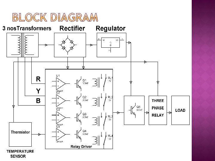
� Project overview � Block diagram � Power supply � Thermistor � Comparator � Relay � Schematic & Working of the project � Advantages � Applications � Future scope � Conclusion

� The basic idea for the development of the project is to provide safety to the Induction Motor. � If any of the phases, out of the 3 phases is missing and also if the temperature of the motor during operation exceeds the prescribed value, the supply to the induction motor is cut off immediately. � The kit is supplied with a 3 phase power i. e. , the three transformers are connected to the 3 phases supply.
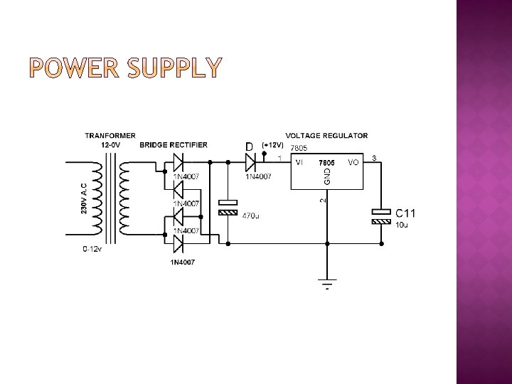

� The 230 V AC supply is first stepped down to 12 V AC using a step down transformer. � This is then converted to DC using bridge rectifier. � The AC ripples is filtered out by using a capacitor and given to the input pin of voltage regulator 7805. � At output pin of this regulator we get a constant 5 V DC which is used for MC and other ICs in this project. � A blocking diode is connected to take the pulsating waveform.

�A thermistor is a type of resistor whose resistance varies significantly (more than in standard resistors) with temperature. � The word is a portmanteau of thermal and resistor. � Thermistors are widely used as inrush current limiters, temperature sensors, self-resetting over current protectors, and self-regulating heating elements.

� op amps & comparators look very similar � But a comparator gives a logic output indicating the relative potentials on its two inputs � An op amplifies the differential voltage between its two inputs – and is designed always to be used in closed-loop applications

� Potential dividers are connected to the inverting and non inverting inputs of the op-amp to give some voltage at these terminals. � Supply voltage is given to +V and –V is connected to ground. � The output of this comparator will be logic high (i. e. , supply voltage) if the non-inverting terminal input is greater than the inverting terminal input of the comparator. � If the inverting terminal input is greater than the non-inverting terminal input then the output of the comparator will be logic low (i. e. , gnd).

�A relay is an electrically operated switch. � Current flowing through the coil of the relay creates a magnetic field which attracts a lever and changes the switch contacts. � The coil current can be on or off so relays have two switch positions and have double throw (changeover) switch contacts as shown in the diagram.

� Relays allow one circuit to switch a second circuit which can be completely separate from the first. � For example a low voltage battery circuit can use a relay to switch a 230 V AC mains circuit. � There is no electrical connection inside the relay between the two circuits, the link is magnetic and mechanical. � To drive relay through MC ULN 2003 relay driver IC is used

� In normal operations RV 1, RV 2, RV 3 & RV 4 are so set that the output of the comparators is held low resulting in 4 relays in deactivated condition while the 3 CO relay is in active operation. � In the event of failure of any phase the corresponding comparator output goes high that drives the relay the contact of which opens to discontinue the DC supply to the 3 CO relay. � The phase motor connected in series with the NO contacts thus open to stop the motor. � Similarly while the temperature goes high on the body of the motor the mounted Thermistor resistance falls to develop logic high for Q 4 to operate R 4 & disconnect the DC voltage to the 3 CO relay. � Thus in the process motor is protected against any phase failure or high temperature.

- Slides: 13