Subject Name Digital Communication Subject Code 10 EC

Subject Name: Digital Communication Subject Code: 10 EC 61 Prepared By: Lakshmi C R, Pallavi Department: ECE Date: 1. 3. 15 Engineered for Tomorrow Prepared by : Pavana H Department : ECE Date : 24. 12. 2013

UNIT 1 INTRODUCTION TO DIGITAL COMMUNICATION

Contents 1. Introduction 2. Sampling process and theorem 3. Quadrature sampling of band pass signal 4. Practical aspects of sampling 5. Signal recovery

INTRODUCTION • Communication is the activity of conveying information through the exchange of thoughts, messages, or information, as by speech, visuals, signals, writing, or behavior

MODEL OF A COMMUNICATION SYSTEM • The three basic elements of every communication systems are Transmitter, Receiver and Channel.

• The purpose of the transmitter is to transform the message signal produced by the source of information into a form suitable for transmission over the channel. • The received signal is normally corrupted version of the transmitted signal, which is due to channel imperfections, noise and interference from other sources. • The receiver has the task of operating on the received signal so as to reconstruct a recognizable form of the original message signal and to deliver it to the user destination

Basic Types of Communication system • Analog Communication Systems are designed to transmit analog information using analog modulation methods. • Digital Communication Systems are designed for transmitting digital information using digital modulation schemes • Hybrid Systems that use digital modulation schemes for transmitting sampled and quantized values of an analog message signal.

Basic signal processing operations in digital communication

Elements of Digital Communication • Source of Information: 1. Analog Information Sources. 2. Digital Information Sources. • Analog Information Sources → Microphone actuated by a speech, TV Camera scanning a scene, continuous amplitude signals. • Digital Information Sources → These are teletype or the numerical output of computer which consists of a sequence of discrete symbols or letters.
 converts the input")
• Source Encoder: The Source encoder ( or Source coder) converts the input i. e. symbol sequence into a binary sequence of 0‟s and 1‟s by assigning code words to the symbols in the input sequence. • At the receiver, the source decoder converts the binary output of the channel decoder into a symbol sequence. Ex: Huffman coding.

CHANNEL ENCODER / DECODER • Error control is accomplished by the channel coding operation that consists of systematically adding extra bits to the output of the source coder. • These extra bits do not convey any information but helps the receiver to detect and / or correct some of the errors in the information bearing bits. • There are two methods of channel coding (1) Block Coding (2) Convolution coding

MODULATOR & DEMODULATOR • MODULATOR : The Modulator converts the input bit stream into an electrical waveform suitable for transmission over the communication channel. (1) Modulator can be effectively used to minimize the effects of channel noise (2)It is used to match the frequency spectrum of transmitted signal with channel characteristics • DEMODULATOR: The extraction of the message from the information bearing waveform produced by the modulation is accomplished by the demodulator.

SAMPLING PROCESS • SAMPLING : The process by which the continuous-time signal is converted into a discrete–time signal is called Sampling.

Sampling Theorem for Low pass Signals • Statement: - “If a band –limited signal g(t) contains no frequency components for ׀ f < ׀ W, then it is completely described by instantaneous values g(k. Ts) uniformly spaced in time with period Ts ≤ 1/2 W. • If the sampling rate, fs is equal to the Nyquist rate or greater (fs ≥ 2 W), the signal g(t) can be exactly reconstructed.
 is sampled by using a train")
• Proof: - Consider the signal g(t) is sampled by using a train of impulses sδ (t). Let gδ(t) denote the ideally sampled signal, can be represented as,
 • Nyquist Rate Sampling (fs =")
• Over Sampling (fs > 2 W) • Nyquist Rate Sampling (fs = 2 W)

Under Sampling
 through an low pass filter")
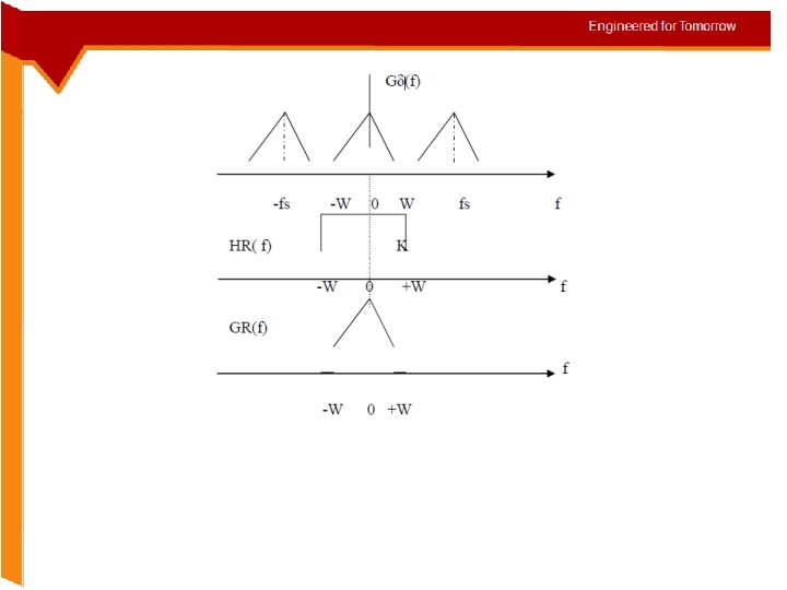
• By passing the ideally sampled signal gδ(t) through an low pass filter ( called Reconstruction filter ) (1) having the transfer function HR(f) with bandwidth, B (2)satisfying thecondition W ≤ B ≤ (fs – W) , we can reconstruct the signal g(t).

Spectrum of sampled signal and reconstructed signal

Quadrature Sampling of Band – Pass Signals • In this scheme, the band pass signal is split into two components, one is in-phase component and other is quadrature component. • These two components will be low–pass signals and are sampled separately. This form of sampling is called quadrature sampling.

Generation of in-phase and quadrature phase samples
 Spectrum of Band-pass signal g(t) b) Spectrum of in-phase and quadrature phase signals")
a) Spectrum of Band-pass signal g(t) b) Spectrum of in-phase and quadrature phase signals Let g(t) be a band pass signal, of bandwidth 2 W‟ centered around the frequency, fc, (fc>W)
=g(t). cos(2πfct) • quadrature phase component= g(t). sin(2πfct) The")
• in-phase component, g. I(t)=g(t). cos(2πfct) • quadrature phase component= g(t). sin(2πfct) The band pass signal g(t) can be expressed as, g(t) = g. I(t). cos(2πfct) – g. Q(t) sin(2πfct) • The in-phase, g. I(t) and quadrature phase g. Q(t) signals are low –pass signals, having band limited to (-W < f < W).
 • From the sampled signals g. I(n. Ts) and")
Reconstruction of Band-pass signal g(t) • From the sampled signals g. I(n. Ts) and g. Q(n. Ts), the signals g. I(t) and g. Q(t) are obtained. • To reconstruct the original band pass signal, multiply the signals g. I(t) by cos(2πfct) and sin(2πfct) respectively and then add the results.

Natural Sampling: Natural Sampling – Simple Circuit. In this method of sampling, an electronic switch is used to periodically shift between the two contacts at a rate of fs = (1/Ts ) Hz, staying on the input contact for C seconds and on the grounded contact for the remainder of each sampling period
=output, x(t)=input, s(t)= sampling function xs(t) = x(t). s(t) The")
Natural Sampling – Waveforms. xs(t)=output, x(t)=input, s(t)= sampling function xs(t) = x(t). s(t) The sampling function s(t) is periodic with period Ts, can be defined as,
 as where the Fourier coefficients,")
Using Fourier series, we can rewrite the signal S(t) as where the Fourier coefficients, Therefore: Applying Fourier transform for the above equation
")
Message Signal Spectrum Sampled Signal Spectrum (fs > 2 W)

Flat Top Sampling: In this method, the sampled waveform produced by practical sampling devices, the pulse p(t) is a flat – topped pulse of duration, Flat Top Sampling Circuit

Waveforms

Mathematically we can consider the flat – top sampled signal as equivalent to the convolved sequence of the pulse signal p(t) and the ideally sampled signal, x δ (t). Applying F. T
 Sample and Hold Circuit b) Idealized")
Sample and Hold Circuit for Signal Recovery a) Sample and Hold Circuit b) Idealized output waveform of the circuit

The Sample-and-Hold circuit consists of • Amplifier of unity gain. • Low output impedance • A switch and a capacitor • It is assumed that the load impedance is large

Working of Sample and hold circuit • The switch is timed to close only for the small duration of each sampling pulse, during which (1)The capacitor charges up to a voltage level equal to that of the input sample • When the switch is open , the capacitor retains the voltage level until the next closure of the switch. • Thus the sample-and-hold circuit produces an output waveform that represents a staircase interpolation of the original analog signal.
= impulse response Correspondingly, the")
The output of a Sample-and-Hold circuit is defined as h(t)= impulse response Correspondingly, the spectrum for the output of the Sample-and-Hold circuit is given by,
 without")
Components of a scheme for signal reconstruction To recover the original signal g(t) without distortion, the output of the Sample-and-Hold circuit is passed through a low-pass filter and an equalizer.

Advantages of Digital Communication • The effect of distortion, noise and interference is less in a digital communication system. • Regenerative repeaters can be used at fixed distance along the link, to identify and regenerate a pulse before it is degraded to an ambiguous state. • Digital circuits are more reliable and cheaper compared to analog circuits.

• Signal processing functions like encryption, compression can be employed to maintain the secrecy of the information. • Error detecting and Error correcting codes improve the system performance by reducing the probability of error. • The Hardware implementation is more flexible than analog hardware because of the use of microprocessors, VLSI chips etc. • Combining digital signals using TDM is simpler than combining analog signals using FDM

Problem-1: An analog signal is sampled at the Nyquist rate fs = 20 K and quantized into L=1024 levels. Find Bit-rate and the time duration Tb of one bit of the binary encoded signal. Solution: Assume Bit-rate = Rb = nfs = 200 K bits/sec Bit duration Tb = 1/ Rb = 5µsec. Mid-rise type, n = log 2 L = 10

Problem-2: A PCM system uses a uniform quantizer followed by a 7 -bit binary encoder. The bit rate of the system is 56 Mega bits/sec. Find the output signal-toquantization noise ratio when a sinusoidal wave of 1 MHz frequency is applied to the input. Solution: Given n = 7 and bit rate Rb = 56 Mega bits per second. Sampling frequency = Rb/n = 8 MHz Message bandwidth = 4 MHz. For Mid-rise type (SNR)0 = 43. 9 d. B

DISCUSSION Explain the term quadrature sampling of band pass signal with help of spectrum and block diagrams (Dec 2010) 1. In this scheme, the band pass signal is split into two components, one is in-phase component and other is quadrature component. These two components will be low–pass signals and are sampled separately. This form of sampling is called quadrature sampling. 2. Let g(t) be a band pass signal, of bandwidth ‘ 2 W’ centered around the frequency, fc, (fc>W). The in-phase component, g. I(t) is obtained by multiplying g(t) with cos(2πfct) and then filtering out the high frequency components.
 with sin(2πfct) and")
3. Parallelly a quadrature phase component is obtained by multiplying g(t) with sin(2πfct) and then filtering out the high frequency components. . The band pass signal g(t) can be expressed as, g(t) = g. I(t). cos(2πfct) – g. Q(t) sin(2πfct) 4 The in-phase, g. I(t) and quadrature phase g. Q(t) signals are low–pass signals, having band limited to (-W < f < W). Accordingly each component may be sampled at the rate of 2 W samples per second. sin (2πfct)
 = 10 cos (20 Πt) cos(200Πt) is sampled at the")
2. The signal g(t) = 10 cos (20 Πt) cos(200Πt) is sampled at the rate of 250 samples per second. i) Determine the spectrum of the resulting sampled signal and sketch ii) Specify the cut-off frequency of the ideal reconstruction filter so as recover f(t) from the sampled version and also find the Nyquist rate. (june 2012)

Spectrum of a Band pass signal. Spectrum of in-phase and quadrature phase signals

The spectrum appears as The nyquist rate is 2 fm=2*110=220 Hz
 With neat block diagram explain the operation of digital communication system. Explain the")
3) With neat block diagram explain the operation of digital communication system. Explain the functioning of each block. (june 2012)
 The Source encoder ( or Source coder) converts the")
SOURCE ENCODER / DECODER: (a) The Source encoder ( or Source coder) converts the input i. e. symbol sequence into a binary sequence of 0’s and 1’s by assigning code words to the symbols in the input sequence. (b) The important parameters of a source encoder are block size, code word lengths, average data rate and the efficiency of the coder. (c) At the receiver, the source decoder converts the binary output of the channel decoder into a symbol sequence. The decoder for a system using fixed – length code words is quite simple, but the decoder for a system using variable – length code words will be very complex. ] (d) Aim of the source coding is to remove the redundancy in the transmitting information, so that bandwidth required for transmission is minimized Ex: Huffman coding

CHANNEL ENCODER / DECODER: • Error control is accomplished by the channel coding operation that consists of systematically adding extra bits to the output of the source coder. These extra bits do not convey any information but helps the receiver to detect and / or correct some of the errors in the information bearing bits. There are two methods of channel coding: (a) Block Coding (b) Convolution Coding The Channel decoder recovers the information bearing bits from the coded binary stream. Error detection and possible correction is also performed by the channel decoder

MODULATOR: The Modulator converts the input bit stream into an electrical waveform suitable for transmission over the communication channel. DEMODULATOR: The extraction of the message from the information bearing waveform produced by the modulation is accomplished by the demodulator. The output of the demodulator is bit stream. The important parameter is the method of demodulation CHANNEL: The Channel provides the electrical connection between the source and destination • The communication channels have only finite Bandwidth, non-ideal frequency response, the signal often suffers amplitude and phase distortion as it travels over the channel
 State and prove sampling theorem for wide sense stationary message process. whose power")
4) State and prove sampling theorem for wide sense stationary message process. whose power spectrum Is strictly band limited. Ans: The process by which the continuous-time signal is converted into a discrete–time signal is called Sampling SAMPLING THEOREM FOR LOW-PASS SIGNALS: • Statement: - “If a band –limited signal g(t) contains no frequency components for ׀ f < ׀ W, then it is completely described by instantaneous values g(k. Ts) uniformly spaced in time with period Ts ≤ 1/2 W. If the sampling rate, fs is equal to the Nyquist rate or greater (fs ≥ 2 W), the signal g(t) can be exactly reconstructed.
 is sampled by using a train of impulses")
proof: - Consider the signal g(t) is sampled by using a train of impulses sδ (t). Let gδ(t) denote the ideally sampled signal, can be represented as gδ(t) = g(t). sδ(t) where sδ(t) – impulse train defined by

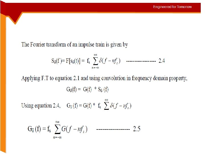
The Fourier transform of an impulse train is given by Applying F. T to equation and using convolution in frequency domain property
")
Over Sampling (fs > 2 W)
")
Nyquist Rate Sampling (fs = 2 W)
 Reconstruction of g(t) from g δ (t): By")
Under Sampling (fs < 2 W) Reconstruction of g(t) from g δ (t): By passing the ideally sampled signal gδ(t) through an low pass filter ( called Reconstruction filter ) having the transfer function HR(f) with bandwidth, B satisfying the condition W ≤ B ≤ (fs – W) , we can reconstruct the signal g(t).
 = gδ (t) * h. R(t)")
The output of LPF is, g. R(t) = gδ (t) * h. R(t) where h. R(t) is the impulse response of the filter. In frequency domain, GR(f) = Gδ(f). HR(f). For the ideal LPF HR(f) = K -W ≤ f ≤ +W 0 otherwise then impulse response is h. R(t) = 2 WTs. Sinc(2 Wt)

• Correspondingly the reconstructed signal is

ASSIGNMENT QUESTIONS Unit 1: 1. Write a note on communication channels. 2. Explain the effect of aliasing and how it can be avoided? 3. The signal g 1(t)=10 cos 100Πt and g 2(t)=10 cos 50 Πt. Show that 2 sequences are identical. 4. Explain sample and hold circuit. 5. With derivation explain flat top sampling. 6. State natural sampling along with expression explains it. 7. State and prove sampling theorem. 8. What is aperture effect? How it can be avoided or eliminated? 9. Mention merits and demerits of digital communication 10. Compare analog and digital communication.
- Slides: 60