Study of Gain Uniformity of Micromegas with thermobond

Study of Gain Uniformity of Micromegas with thermo-bond film separators Liang Guan 1, Zhi. Yong Zhang 1, Xiao. Lian Wang 1, Zi. Zong. Xu, Tian. Chi Zhao 2 1 University of Science and Technology of China, Hefei, China 2 University of Washington, Seattle, USA

Outline • Micromegas study at USTC • Simple garfield simulation of gas gain • study in the lab • Summary

Micromegas study at USTC 350 LPI Thermal bond film frame ◦ Micro. Mesh: 350 LPI woven stainless steel mesh pitch/wire diameter 70/22 mm ◦ Mesh Tension: measured by tensometer, well controlled Tension: 17 -19 N/cm tough polyester films with a permanent, dry (hot-melt type) adhesive on both sides Mesh stretching & conditioning

Micromegas achieved by photoengraving Mesh Pillar spacers PCB Easily obtained , much cheaper and most important, it works well! Micromegas with a thermal bond film frame Mesh Avalanche region PCB Thermal bond film frame But nothing is perfect ! Because of there is no spacer among the avalanche area, the uniformity of the gap which directly affects the gain uniformity will become a great challenge , especially for larger active area development. Affecting factors of gain uniformity in the Micromegas with thermal-bond film spacers ▪ ▪ Warp of readout PCB Mesh sagging by electrostatic attraction Uniformity of melt of thermal bond film Gas properties

Uniformity Study I. Gas Composition

Gain uniformity test of TPC-Mm-01 n n Test with Fe-55 x-ray source Ar/CO 2 93/7; Ne/CF 4 95/5; Collimator: 4 cm (Height) ø 3 mm hole Scan over 20~25 mm with step size of 5 mm Scan over 25 mm with step size of 5 mm along a direction shown as below: active area -1. 5 -1 -0. 5 0 0. 5 1 1. 5 Garfield simulation Test in the lab(gas-flow mode )

Ar-i. C 4 H 10 90/10, Avalanche Gap 120 mm -5 mm Corresponds to normally used operational amplification field: 30 KV/cm~50 KV/cm -Vmesh Gain Var. 500 V 20% 400 V 13%

II. Mesh sagging vs HV and mesh tension Spacing test IEEE-NSS paper ID: N 48 -237 Tension test Spacing: Proto Mm 07 4 mm Proto Mm 15 3 mm 160μm Bond film frame 10 MΩ PCB -HV (N 471 A)
 kg/cm 2 Mesh tension (y) kg/cm 2 Voltage starts to spark")
Mesh tension (x) kg/cm 2 Mesh tension (y) kg/cm 2 Voltage starts to spark 0. 37 0. 36 850 0. 59 0. 56 930 0. 79 0. 75 940 1. 28 1. 21 1020 mesh sagging observed @Vm>800 V III. Defects during fabrication Bowing of anode PCB affects gap uniformity Back-plane Supports improve the gain uniformity: var. 20% 5% over 40 mm

summary • Garfield simulation and experimental test have been done for different gas mixture and gas gain in neon gas mixture seems less sensitive to avalanche gap. • The mesh tension should bigger than 15 N/cm and the spacing without spacers should smaller than 3*3 square cm(for large area micromegas development ). • Honeycomb plates have been used to rectify the warp of readout PCB. 11/1/2021

Performance study of Micromegas + THGEM hybrid Yuehuan Wei 2, Zhiyong Zhang 1, Liang Guan 1, Kaixuan Ni, Boxiang Yu 3 1 University of Science and Technology of China, Hefei, China 2 Shanghai Jiao Tong University, Shanghai, China 3 Institute of High Energy Physics, Beijing, China • Introduction • General feature of Micromegas and GEM • Main results of double-structure test

Introduction Numerous proposed solutions to charge detection in the gas phase of noble liquids Possible applications: -) Noble liquid ionization calorimeters -) Liquid argon TPC (solar neutrinos) -) Scintillation detectors and two-phase emission detectors Rare events and exotic particles searches (WIMP …) -) Development of new instrumentation for nuclear medicine imaging g-camera for PET For possible application of a gaseous PMT for dark matter detection Required sensitive to low energy photons(sub-Ke. V). A. Breskin, R. Chechik, M. Cortesi, R. Alon, J. Miyamoto Weizmann institute of science, Rehovot, Israel José Matias Atomic and Nuclear Instrumentation Group University of Coimbra Portugal

Mmegas+THGEM double-structure • THGEM p Diameter 57 mm p hole diameter = 0. 3 mm p hole spacing = 0. 7 mm p rim around hole h <0. 1 mm Gas mixture: Neon: CF 4(95: 5) , gas pressure: 1 atm drift gap: 5 mm; Transfer gap (drift region of Micromegas): 2 mm • Micromegas p 30 mm× 30 mm active area p ~100 um avalanche gap achieved by using thermal-bond film p Readout channel: 25 (use 34 pin connector+ ribbon cable) p Filter network integrated p Mesh signal readout circuit for trigger, spark counting

• Test Setup HV feed-throughs Vacuum gage BNC To vacuum pump Ne+CF 4(95: 5) filling pipe micromesh Transfer gap: 2 mm THGEM(top and bottom layer) (-HV) Drift gap: 5 mm Drift electrode (-HV) Collimator: 4 cm (Height) ø 3 mm hole Fe 55 source(~) Ф=95 mm

• Installation THGEM view Drift electrode Teflon spacer Micromegas view Fe 55 source and organic glass collimator

Transparency and drift , transfer electric field set Single GEM Effective gain as a function of GEM voltage for different collection electric fields. Micromegas transparency test Relative transparency as a function of drift field for several GEM voltages and collection fields of 2 k. V/cm Sanghyo Han and Heedong Kang, Journal of the Korean Physical Society, Vol. 40, No. 5, May 2002 Ed~0. 3 -0. 4 k. V/cm(vs Etransfer of double-structure)

Test was terminated by sparking of HV feed-through at drift electrode voltage ~1500 V. The energy resolution at Edrift=Etransfer=1 k. V/cm seems not good.

Energy resolution of this double-structure mainly lies on the THGEM Voltage

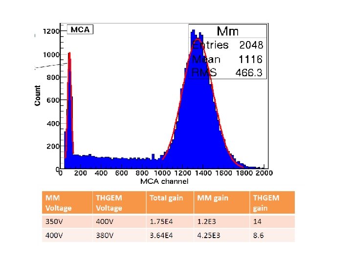
Merged view Biggest gas gain is of 1. 5*10^5 obtained at Vm=350 V, Vthgem=500 V vs about 2. 5*10^7 charges in the avalanche gap of micromegas in total. Best ER is of ~21%(FWHM) obtained at low Micromesh(Vm=350 V) voltage and high THGEM voltage
 1 atm 20. 6%(FWHM) Vm=350 V Δvthgem=500 V")
Gas mixture: Ne: CF 4(95: 5) 1 atm 20. 6%(FWHM) Vm=350 V Δvthgem=500 V Edrift=Etransfer=0. 5 k. V/cm Temperature: ~298 K

Long time stability Vm=400 V Vthgem=400 V ; Edrift=Etransfer=0. 3 k. V/cm ; amp=5
 gas")
summary • Micromegas and THGEM hybrid have been test in Ne+CF 4(95: 5) gas mixture at 1 atm. • Highest gain obtained is 1. 5*10^5 for Fe 55 X-ray. • Best energy resolution is of about 21%. • Possible application for gas PMT need further study.

! u o ky n a Th Backup slides

Calibration of electronic chain • pulse generator: Pulse setting BNC model: PB-5 ortac caen: ortac: model: 855 dual model: N 858 model: 142 AH rise time 50 ns fall time 100 us width: 400 us rate: 200 HZ coupling: 50 ohm • main Amplifier: • attenuator: • Pre-amplifier:

Calibration of electronic chain Attenu ation 3 d. B calibrat 0. 592 ion 6 d. B 9 d. B 0. 385 0. 262 Linear fit Y= 8. 22027 E-4 *x+ 7. 52686 E-4 main amp *10 attenuation *0 d. B ) to main amp *10) Y: Quantity of charges(p. C) Y=(0. 01112+x)*5. 374 E-4 calibrated by Guan. Liang before. x: peak (normalized

16. 8% Vm=540 V Vd=935 V
- Slides: 27