Study of Beam Current Monitors Shourya Mukherjee 9
 Under guidance of")
Study of Beam Current Monitors -Shourya Mukherjee (9 th July 2019) Under guidance of Prof. Takeshi Toyama, Prof. Kenichirou Satou

I am pursuing Electrical Engineering from Indian Institute of Technology Kharagpur. Here, I am working with the Beam Monitor group of J-PARC MR. As MR is out of commission, all analysis based on RCS! West Bengal IIT-KGP Kolkata

Beam Intensity Measurements Beam diagnostics is an essential constituent of any accelerator. It deals with the real beam including all possible imperfections. Continuously monitoring and optimizing beam intensity is very important during operation of accelerators. A certain system covers a limited range of intensities, due to many types of ion species having a wide range of energies and charge states, and a great variety in the time structure. The current monitors used in general are: 1) Faraday Cups 2) Beam Current Transformers (DCCT/SCT/MCT/FCT) 3) Wall Current Monitors
")
Diagnostic Systems in RCS Rapid Cycling Synchrotron (from 2008)
 The DCCT measures an intensity of a circulating")
Direct Current – Current Transformer (DCCT) The DCCT measures an intensity of a circulating beam. It is important to keep track if protons are being lost per turn or not. Current transformers cannot measure this due to limitation in their frequency response.

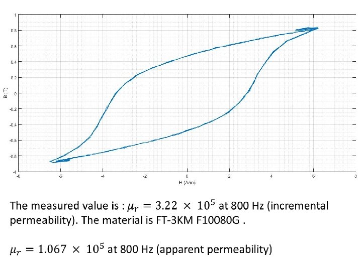
Magnetic Properties of the Cores FINEMET is a nano-crystalline soft magnetic material which is used to make the toroidal cores for the DCCTs. This material is superior to normal Febased amorphous metal. 1) High saturation magnetic flux density and high permeability. 2) Low core loss 3) Wide frequency range V_out

Wall Current Monitor The Wall Current Monitor intercepts the image current induced on the walls of the vacuum tubes. The WCM measures the intensity and the longitudinal profile of the beam. The bandwidth of these devices exceeds 1 GHz. A WCM can be modeled by a parallel RLC circuit as shown.

This is the response of a WCM installed in the RCS. The repetition rate of RCS is 25 Hz i. e. 40 ms. And we are looking at the acceleration time which is 20 ms. Sampling time is 20 ns. 9

This is the FFT of the response of WCM. The RF frequency varies from 1. 229 MHz – 1. 671 MHZ which along with its harmonics are visible here. 10

From the WCM, one 4 us frame has been cut. Bunches RF clock

Longitudinal Beam Dynamics It deals with the motion of the beam along the orbit. Many important parameters such as frequency ramping, energy gain, phase stability were calculated for RCS. The variation of synchronous phase per turn is a very important parameter. The repetition rate of RCS is 25 Hz i. e. a total acceleration time of 20 ms. The maximum phase (theoretically) is 44. 31 degrees.

From the WCM, we can cut frames synchronously and put it together to get this type of “mountain plots”. Here 2 bunches can be seen. Turns Time (x 20 ns)

Longitudinal Phase Space Tomography is imaging through sectioning. The idea is to get projections of an object at various angles and from those projections to recreate the original object. Different algo. : 1)BP 2)Filtered BP 3)Convolution BP

The beam profiles seen by the WCM can be thought as projections of the beam at different angles. Thus from those 1 D profiles, we can use CBP to create 2 D beam structure.

Longitudinal CBP Tomography at extraction at last 1 ms in RCS from 3 rd July 2019 data.

Thank You!

18

Difference equation of motion VRF t

at injection one period in phase space ~ 230 turns of the ring Trev ~ 1. 63 ms “synchrotron oscillation” frequency ~ 1/(230 x Trev) ~ 2. 6 k. Hz
- Slides: 20