StructuresTrusses Objectives To introduce a trussstructure system To

Structures-Trusses

Objectives • To introduce a truss-structure system • To define truss • To demonstrate the types of trusses

Introduction • For the equilibrium of structures which are made up of several connected parts, the internal forces as well the external forces are considered. • In the interaction between connected parts, Newton’s 3 rd Law states that the forces of action and reaction between bodies in contact have the same magnitude, same line of action but opposite sense. RAy ∑Fx=0: RAx=0 6 -3 • Three categories of engineering structures are considered: a) Trusses: formed from two-force members, i. e. , straight members with end point connections. b) Frames: contain at least one multi-force member, i. e. , member acted upon by 3 or more forces. c) Machines: structures containing moving parts designed to transmit and modify forces.

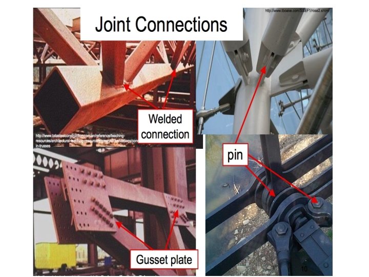
Definition of a Truss • A truss consists of straight members connected at joints. No member is continuous through a joint. • Most structures are made up of several trusses joined together to form a space framework. Each truss carries those loads which act in its plane and may be treated as a two-dimensional structure. • Bolted or welded connections are assumed to be pinned together. Forces acting at the member ends reduce to a single force and no moment. Only twoforce members are considered. • When forces tend to pull the member apart, it is in tension. When the forces tend to compress the member, it is in compression. 6 -4

Definition of a Truss Members of a truss are slender and not capable of supporting large lateral loads. Loads must be applied at the joints of truss. 6 -5

Definition of a Truss 6 -6

Plane and Space Trusses • Plane Trusses: Plane trusses are composed of members that lie in the same plane and are frequently used for bridge and roof support. • Space Trusses: Space trusses are composed of members that extent in three dimensions and are suitable for derricks (a type of crane) and towers. 7

Truss Stability

Types of a Trusses 6 -9

Examples of Trusses The roof truss shown is formed by two planar trusses connected by a series of purlins. 6 - 10

A wooden Roof Truss 11

Examples of Trusses 6 - 12 Since roof trusses, such as those shown, require support only at their ends, it is possible to construct buildings with large unobstructed floor areas.

A Bridge Truss 13

A railway Bridge Truss 14
 15")
Space truss (towers) 15

Simple Trusses • A rigid truss will not collapse under the application of a load. • A simple truss is constructed by successively adding two members and one connection to the basic triangular truss. • In a simple truss, m = 2 n - 3 where m is the total number of members and n is the total number of joints. 6 - 16

Analysis of Simple Trusses Assumptions • All members are two force members T T C C • Weight of the member is small compared with the force it supports. • The members are joined together by smooth pins. • All external forces are applied at the pin connections (e. g. in bridge trusses the deck is usually laid on cross beams which are supported at the joints) 17

- Slides: 19