Structural Design of Commercial Building under Gravity and

Structural Design of Commercial Building under Gravity and Seismic Loads Prepared By: Razan Zaidan Rawya Amarneh Under Supervision of: Dr. Mohammed Samaaneh.

v. Presentation Contents: 1 - Project Description. 2 - Site and Geological Information. 3 - General Notes. 4 - Preliminary Design of the Project. 5 - 3 D Modeling and Design of the Project.
 Use of floor Third Basement 969. 8")
• Project Description: Floor Height (m) Use of floor Third Basement 969. 8 3 Parking Second Basement 969. 8 3 Parking First Basement 969. 8 3 Stores Ground 878. 0 3 Gallery First floor 954. 3 3 Gallery Second floor 954. 3 3 Gallery Third floor 954. 3 3 Gallery and apartments Fourth floor 954. 3 3 Gallery and apartments Fifth floor 954. 3 3 Gallery and apartments Sixth floor 954. 3 3 Gallery and apartments Seventh floor 954. 3 3 Gallery and apartments Staircase 78. 9 2. 85 - Total 10546. 5 35. 85 -

Basment Floors Plan.

Ground Floor Plan

Upper Floors Plan.

• Site Geological and Information: •

• General notes: 1 - Concrete compressive strength = 24 Mpa. 2 - Steel yield strength of 420 Mpa. 3 - The soil bearing capacity is 250 kn/m^2. 4 - Design Codes: o ACI 318 -11. o ASCE 7 -10. o UBC 97. 5 - Design Programs: o SAP 2000 program. o SAFE Program. o Auto. CAD.

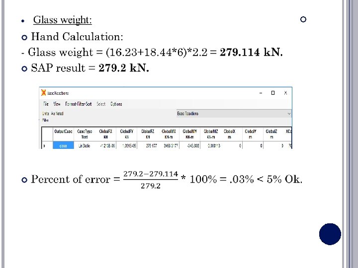
5 - Design loadings: - All floors expect the roof floor: Load Used Value SD Load Live Load Wall Weight 21 k. N/m Glass Weight 2. 2 k. N/m - Roof Floor: Load Used Value SD Load Live Load Wall Weight 14 k. N/m

Preliminary Design of the Structure

• Structural system

ANALYSIS AND DESIGN USING SAP PROGRAM

3 D MODEL OF STRUCTURE

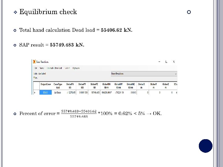
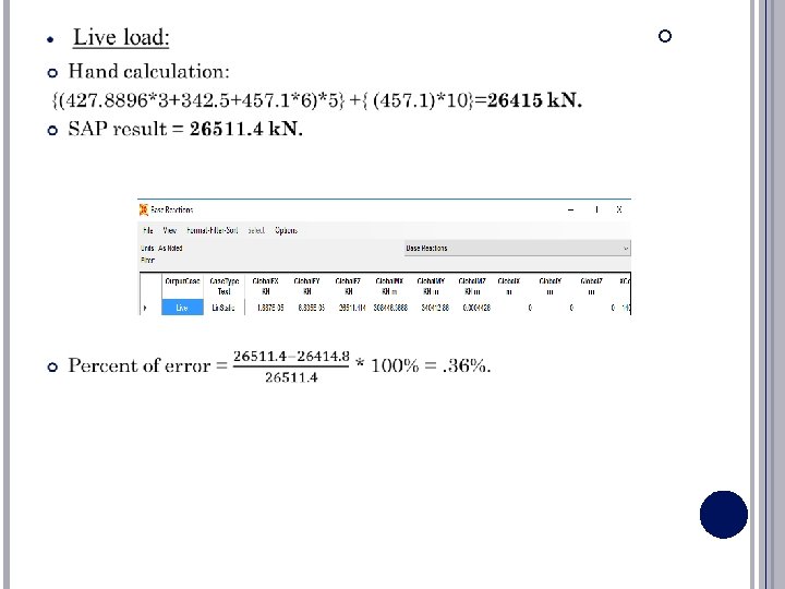
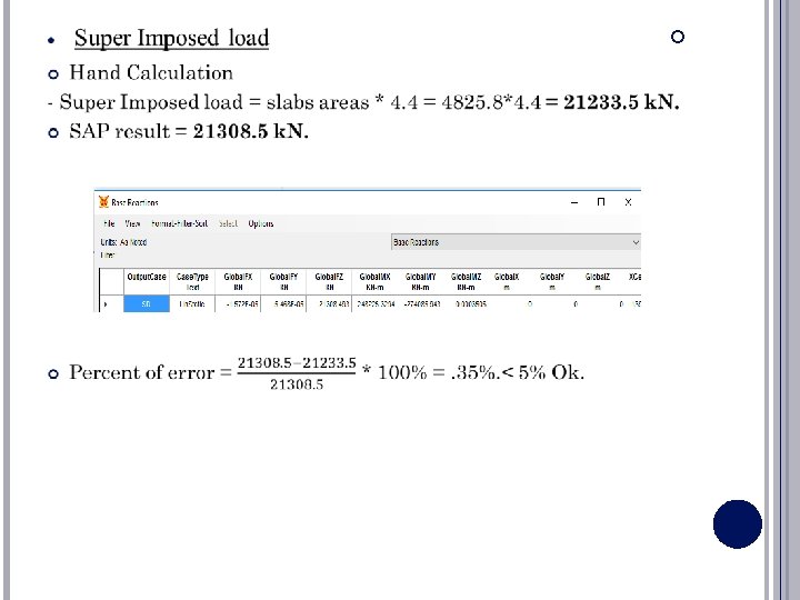
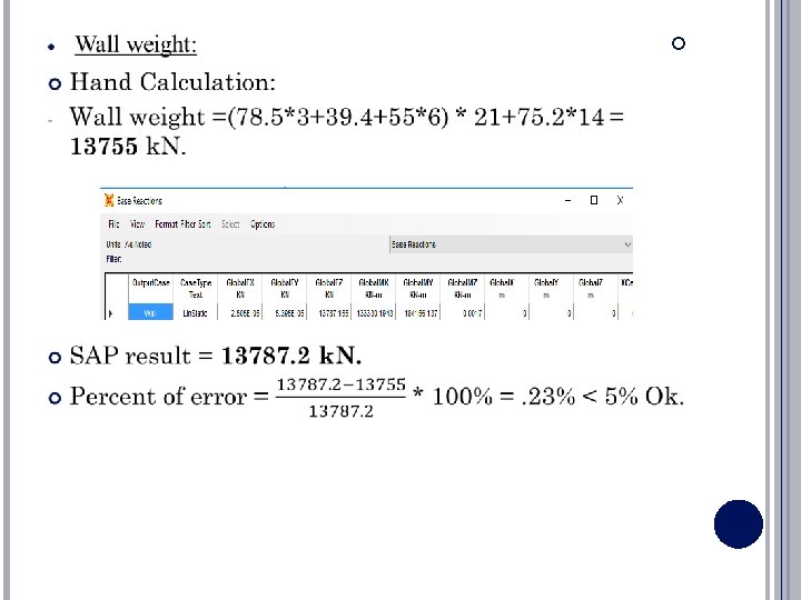
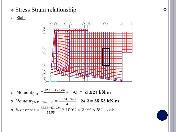
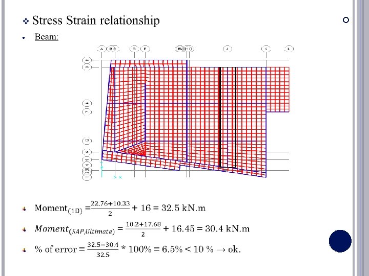
Check of model v. Compatibility check

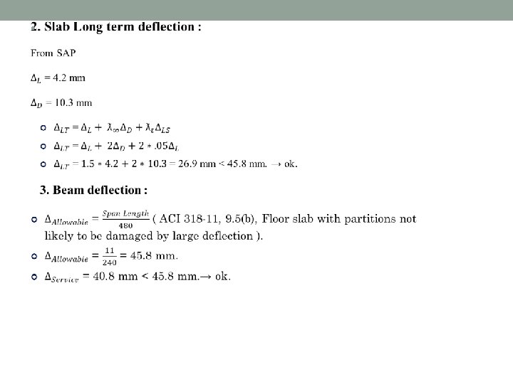
v. Check deflection 1. Slab deflection from service load:
")
• From Section 1630. 2. 2 in UBC 97: • T = (Ct) (hn) ^ (3/4) • T= (0. 03) (108. 27) ^0. 75 = 1 sec. • SAP Result: • T = 1. 85 sec.

SEISMIC ANALYSIS OF THE STRUCTURE

Period Calculations •

v. SAP 2000 Program: • The Value from SAP must be smaller than (1. 4* T Method-A) A. X-direction: - T = 1. 4 Sec. • (1. 4) ( Tmethod A) = (1. 4*1. 01) = 1. 414 Sec. > 1. 4 Sec →OK • Y- direction: • T = 1. 28 Sec. • (1. 4) ( Tmethod A) = (1. 4*1. 01) = 1. 414 Sec. > 1. 28 Sec →OK B.
:")
• Seismic Analysis of the Structure: • Determine seismic zone factor (Z):

• Determine site soil classification: - The Soil profile is found to be (SC). • Determine (Ca) and (Cv) based on site soil classification: - Seismic coefficients: Ca = 0. 24, Cv = 0. 32

• Determine occupancy type: - I = Importance Factor: From table 16 -K—occupancy category in UBC-97. - I = 1. 00 (Standard Occupancy Structures).
:")
o Determine modification factor(R):

• Seismic Analysis Basic Definitions : - Define modal acceleration in X and Y according to (Ritz vectors).

Modal Mass Participation Ratio in X-DIR

Modal Mass Participation Ratio in Y-DIR

• Define Mass Source: - Mass includes = mass of (Dead load + Superimposed dead load + 0. 25 Live load + Wall and Glass load).

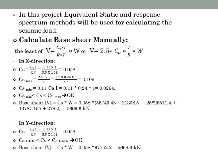
v. Equivalent static method: • Define function of Equivalent static: 1 - In X-Dir:

2 - In Y-Dir:
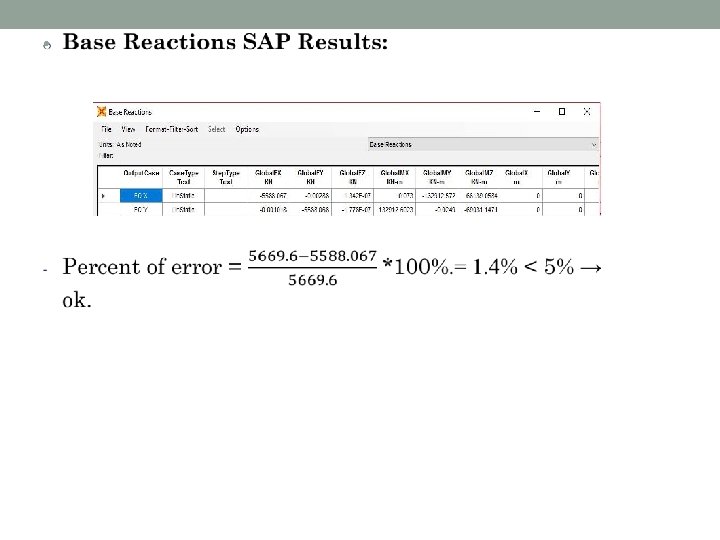

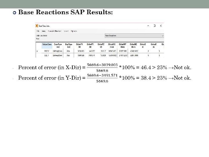
v. Response Spectrum method: - Define function of Response Spectrum: 1 - In X-Dir:

2 - In Y-Dir:
 The code used for design and detailing is")
Structural Design of Concrete Members 1) The code used for design and detailing is ACI 318 -11 regarding seismic and gravity loads. 2) Provisions were applied to all structural members including: Ø Beams Ø Columns Ø Shear Walls Ø slabs Ø Foundations

Structural Design of Concrete Members • Beams layout for the roof

Structural Design of Concrete Members • for B 20 • key for reinforcement

Structural Design of Concrete Members • Longitudinal steel

Structural Design of Concrete Members • Stirrups •

Structural Design of Concrete Members • Beams detailing •

Structural Design of Concrete Members • Column layout

Structural Design of Concrete Members • Check slenderness : For C 10

Structural Design of Concrete Members M 2 =13. 2 k. N. m M 1 =33 k. N. m

Structural Design of Concrete Members • Design load

Structural Design of Concrete Members

Structural Design of Concrete Members • Columns detailing:

Structural Design of Concrete Members • Columns detailing:

Structural Design of Concrete Members • Shear wall:

Structural Design of Concrete Members • Shear Wall detailing:

Structural Design of Concrete Members • Slab detailing for basement

Structural Design of Concrete Members • Footing • SAFE model: • Mat thickness = 1. 3 m

Structural Design of Concrete Members • Deflection check: • Max deflection =0. 7172 mm < 10 mm → ok.
")
Structural Design of Concrete Members • Mat deleting (Y-direction)
")
Structural Design of Concrete Members • Mat deleting (X-direction)

The End 65
- Slides: 65